Janus nanoparticles meet block copolymer scaffolds: on the influence of nanoparticle sizes
Liquan
Wang
,
Jiaping
Lin
* and
Xiaomeng
Zhu
Shanghai Key Laboratory of Advanced Polymeric Materials, Key Laboratory for Ultrafine Materials of Ministry of Education, State Key Laboratory of Bioreactor Engineering, School of Materials Science and Engineering, East China University of Science and Technology, Shanghai 200237, China. E-mail: jlin@ecust.edu.cn; Fax: +86-21-64251644; Tel: +86-21-64253370
First published on 19th October 2012
Abstract
Janus nanoparticles possessing two spherical caps usually exhibit strong interfacial affinity, providing the possibility to create nanocomposites with controlled arrangement of nanoparticles. Here we extended the self-consistent field theory/density functional theory to study the position of the Janus nanoparticles in block copolymer scaffolds. The results demonstrated that the Janus nanoparticles exhibit a size-dependent distribution and orientation in block copolymer scaffolds. The smaller Janus nanoparticles are almost uniformly dispersed in the matrix, while the larger Janus nanoparticles are strongly attached to the interface. Meanwhile, the orientational order parameters of the Janus nanoparticles increase with increasing their sizes. The relative size of the spherical caps also shows a pronounced effect on the Janus nanoparticle distributions. As one of the spherical caps becomes smaller, the Janus nanoparticles partly migrate to the domains preferred by the larger spherical caps, but still remain strongly attached to the interface. The present study can provide an insight into the effect of size on the interfacial activity of the Janus nanoparticles, guiding the design of functional materials with advanced properties.
Introduction
The combination of organic block copolymers and inorganic nanoparticles is able to yield a nanocomposite with cooperative properties.1 Block copolymers can be harnessed as scaffolds to position nanoparticles into ordered arrays with hierarchical controlled size, particle density, and spatial location.2–7 Meanwhile, the unique optical, electric, and magnetic properties of nanoparticles can add significant functionality to such hybrid nanocomposites, creating novel functional materials which may find applications in solar cells, photonic crystals, and high-density magnetic storage media.8–10 To achieve materials with advanced properties, control of the precise position of the nanoparticles is essential. Of particular interest is controlling the assembly of nanoparticles at the interface between different domains of block copolymers. The Janus nanoparticle constitutes an ideal particle for achieving this purpose due to its high interfacial activity.Janus nanoparticles, named after Roman God “Janus”, are compartmentalized colloidal particles comprised of two surface regions with different chemistry or polarity.11 Recent development of chemical synthetic methods has permitted access to Janus nanoparticles with various geometries, including Janus spheres, Janus discs, and Janus cylinders.12–17 Besides the synthesis, the Janus nanoparticles aroused great interest in finding their applications in modern materials and bio-related fields, etc. One of the initial applications is using the so-called Pickering effect for Janus nanoparticles with amphiphilicity.18,19 In a Pickering emulsion, the amphiphilic Janus particles might behave like surfactant molecules to adsorb at the water/air interface, forming a monolayer that de Gennes described as “skin that can breathe”.20 Although the Janus nanoparticles tend to be adsorbed at the interface, their ordering in block copolymer nanocomposites is usually not so simply controlled. The ordering of Janus nanoparticles is determined by the complex competition of enthalpic and entropic effects, which is tuned by controlling the size, shape, and affinity of nanoparticles.
Several publications have appeared concerning the positioning of Janus nanoparticles in polymer blends and block copolymers. For example, Müller et al. used the Janus nanoparticles for the blend compatibilization of two polymers.21 It is shown that the Janus nanoparticles are exclusively located at the interface of the two polymeric phases despite of the high temperature and shear conditions. Although the Janus nanoparticles have a tendency to stick to the interfaces, the equilibrium position of Janus nanoparticles is also influenced by the factors such as the affinity and surface composition of Janus nanoparticles. Favis et al. investigated the effect of the affinity of Janus nanoparticles and found that the Janus nanoparticles consisting of polystyrene (PS) and poly(methyl methacrylate) (PMMA) spherical caps incline to locate at polypropylene (PP) domains due to the stronger affinity between PS and PP.18 Kim et al. studied the influence of the surface compositions on the distributions of the Janus nanoparticles created by the gold nanoparticles coated with mixed PS and poly(2-vinylpridine) (P2VP) brushes within PS-b-P2VP block copolymers. It was found that the Janus nanoparticles move away from the center of the PS domain to interfaces through varying the PS composition on gold surface.22
Compared to the experiments, theoretical calculation and computer simulation can provide a more comprehensive understanding of the polymeric composites filled with the Janus nanoparticles. Kim and Matsen developed a self-consistent field theory with a multi-coordinate-system scheme to study the polymer-coated nanoparticles in lamellar scaffold.23 They not only observed the phenomenon consistent with the experiments carried out by Kim et al.,22 but also provided the underlying mechanism involving the transformation of polymer-coated nanoparticles into Janus particles. In addition, Yan et al. have carried out a mesoscale simulation to explore the geometrical effect on the self-assembly of Janus nanoparticles in block copolymers, which seems hardly systemically investigated in the experiments due to the difficulty in synthesizing Janus nanoparticles with different geometries but same chemical nature.24 The results show that the geometry of Janus nanoparticles dominates the interfacial stabilization of the nanoparticles and kinetic pathway for structural evolution of the nanocomposites. Despite these studies, establishing more detailed knowledge regarding the effect of Janus nanoparticle natures on their positions in block copolymer scaffold is still required for creating nanocomposites with desired structures. For example, until now, how the size of Janus nanoparticles influences the nanoparticle distributions in nanocomposites is still not well understood.
We therefore undertook an investigation on the positioning of the Janus nanoparticles in block copolymer scaffolds, in the framework of self-consistent field theory/density functional theory (SCFT/DFT) developed by Thompson et al.25–32 It was discovered that the nanoparticle size plays an important role in determining the distributions of the Janus nanoparticles in block copolymer scaffold. Larger Janus nanoparticles are found to be strongly attached to the interface. However, when the Janus nanoparticles are smaller or one spherical cap becomes smaller than the other one, they are able to migrate from the interface to the domain of block copolymers. The present study mainly endows us with insight into the size effect of the Janus nanoparticles in nanocomposites, and would provide valuable information for designing structure-controlled hybrid nanocomposites.
Theoretical method
SCFT is a powerful tool for investigating the equilibrium phase behavior of complex fluid.33–42 Recently, Thompson et al. developed a SCFT method for studying the nonpolymeric systems such as the nanoparticle system, hard-rod system, and N2 system, through combining the DFT theory.25–28 In what follows, we extended the SCFT/DFT method for calculating the phase behavior of the Janus nanoparticles in block copolymer scaffolds.The system considered is composed of nJ Janus nanoparticles positioned in a diblock copolymer melt. The Janus nanoparticle is constructed by connecting two different spheres, JA and JB, as shown in Fig. 1. This Janus nanoparticle looks like a dumbbell or snowman, and it is one kind of standard model often found in the literature.43–45 The radii of JA and JB are RJA and RJB, respectively (RJA ≥ RJB). The distance between the centers of two spheres is RJA. The concentration of Janus nanoparticle is cJ. The polymerization degree of AB diblock copolymers is N. The volume fraction of A blocks in diblock copolymers is fA, and thus the volume fraction of B blocks fB = 1 − fA.
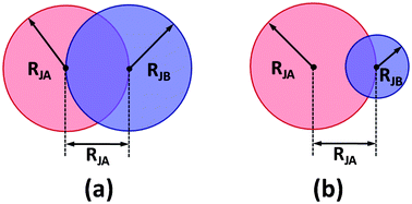 | ||
| Fig. 1 Sketches of the Janus nanoparticles with (a) equal and (b) unequal spherical caps in SCFT/DFT calculations. | ||
Within the SCFT, the free energy density of the present system is given by
 | (1) |
 is the partition function for a single Janus nanoparticle, and
  is the partition function of a single diblock copolymer chain. γα (α = JA, JB) is the sphere-to-diblock volume ratio. The propagator q(r,s) represents the probability to find s segment at position r, where r is rescaled by Rg (
 ). The propagator q(r,s) and backward propagator
 ![[q with combining macron]](https://www.rsc.org/images/entities/i_char_0071_0304.gif) (r,s) satisfy following diffusion equations
(r,s) satisfy following diffusion equations  | (2) |
Here, α = A when s ∈ [0,fA], and α = B when s ∈ [fA,1]. The initial conditions are q(r,0) = 1 and ![[q with combining macron]](https://www.rsc.org/images/entities/i_char_0071_0304.gif) (r,1) = 1, respectively.
(r,1) = 1, respectively.
The hard sphere term ψ(x) has the form of  . The “weighted” nonlocal volume fraction
 ![[small phi, Greek, macron]](https://www.rsc.org/images/entities/i_char_e0d6.gif)
![[small alpha, Greek, macron]](https://www.rsc.org/images/entities/char_e0c2.gif) (r) is given by
(r) is given by
 | (3) |
 | (4) |
 | (5) |
The densities for A block, B block, JA sphere, and JB sphere are given by
 | (6) |
 | (7) |
 | (8) |
Here, the σ is chosen to be the maximum value of |r′|. The prefactor C enforces the normalization condition
 | (9) |
Minimization of the free energy F with respect to ϕα(r)(α = A,B), ρα(r)(α = JA,JB), and ξ(r) yields the following mean-field equations,
 | (10) |
 | (11) |
To find the numerical solutions of the SCFT equations, we adopted a variant of the algorithm developed by Fredrickson and co-workers.46,47 The calculations were performed in a two-dimensional space. The initial random fields that satisfy the Gaussian distributions were first used to seek the structures, and then the “seeding” initial fields were adopted to obtain the defect-free configurations.48 Therefore, the box for the calculations from initial random fields is larger (25.6Rg × 25.6Rg in 256 × 256 lattices), while the box for the calculations from “seeding” initial fields is usually a unit cell. The spatial resolutions were taken to be smaller than 0.1Rg and the contour was discretized with 100 steps. The diffusion eqn (2) were solved with the Baker–Hausdorff operator splitting formula proposed by Rasmussen et al.,49,50 and the eqn (4) and (5) were solved by Gaussian quadratures. The potential fields ωα(r) and pressure filed ξ(r) were updated by means of a two-step Anderson mixing scheme.51,52 The iteration continues until the relative accuracy in the field is smaller than 10−6 and a condition of incompressibility is achieved. To guarantee that the observed morphologies are stable, the free energy was minimized with respect to the sizes of the simulation box, as proposed by Bohbot-Raviv and Wang.53
Results and discussion
In this work, we investigated the location of the Janus nanoparticles in block copolymer scaffolds, under the influence of the Janus nanoparticle sizes. To generate a lamellar scaffold, a symmetric diblock copolymer (fA = 0.5) was adopted. Without specification, the Janus nanoparticles studied bear two spherical caps that are identical in size but opposite in chemical nature (Fig. 1a); that is, one spherical cap is preferentially wetted by the A blocks, while the other is similarly wetted by the B blocks. To achieve such natures, the interaction strengths between the A (B) blocks and JA (JB) spherical caps were set as χAJAN = χBJBN = 0, and the interaction strengths between the dissimilar species were set as χAJBN = χBJAN = χABN = 20. For the cases of RJA = RJB, a unified RJ is used to represent the radius of each spherical cap.Effect of overall size of Janus nanoparticles
The calculations were performed for the Janus nanoparticles with various sizes of RJ. Fig. 2a shows the distributions of the center of the Janus nanoparticles in the lamellar structures. In the figure, the top image shows the corresponding two-dimensional structures of block copolymers, where the red and blue domains are the A and B domains, respectively. The z/D = 0 and z/D = 1.0 correspond to the middle of the B domain. When the RJ is smaller (0.2 and 0.4), the Janus nanoparticles exhibit an almost uniform distribution. The enlargement of these distributions, as presented in the insert, shows that the distributions tend to exhibit small peaks both at the interface and in middle domain. With increasing RJ, the peaks in middle domains disappear, while the peaks at the interface become evident. In the middle domain, the density of nanoparticle center decreases as the RJ increases. At the larger RJ, the distributions exhibit sharp peaks at the interface, implying that the Janus nanoparticles are firmly anchored to the interfaces. Since the volume of the Janus nanoparticles changes with increasing the RJ, the density distribution of the Janus nanoparticles should show some difference. The result is shown in Fig. 2b. In Fig. 2b, only the density of the JA spherical caps was presented due to the symmetry of the Janus nanoparticles. As shown in Fig. 2b, the density distributions are almost uniform at smaller RJ. From the insert of Fig. 2b, we can see that the peaks at the interfaces interfere with each other. With increasing the RJ, the peaks become more overlapped, resulting in a single-peaked distribution in the middle domains at the larger value of RJ. These results demonstrate that although the Janus nanoparticles stick to the interfaces, their densities may show a primary distribution in the middle domain due to their large volumes.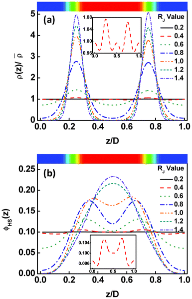 | ||
| Fig. 2 (a) Density distributions of the Janus nanoparticle centers as a function of the displacement z/D normal to the lamella at various nanoparticle sizes RJ. The density ρ(z) is normalized by the mean density of the particle centers. (b) Density distributions of the JA spherical caps as a function of the displacement z/D normal to the lamella at various nanoparticle sizes RJ. The z/D = 0 and z/D = 1.0 correspond to the middle domains rich in the B blocks. The top images show the corresponding two-dimensional structures, where the red and blue regions are assigned to domains rich in A and B blocks, respectively. | ||
In addition to the displacements, the orientational ordering of the Janus nanoparticles is also influenced by the size of the Janus nanoparticles. This influence can be readily observed by examining the angular distribution ρθ of the Janus nanoparticles. The angular distribution ρθ is defined as the normalized volume fraction of the Janus nanoparticles at angle θ, where the θ is the angle between the orientation direction (normal to the JA/JB interface and point to the JA spherical cap) and the direction normal to the lamella (point to the B domain). The definition of θ can be viewed from the inset of Fig. 3. Fig. 3a shows the angular distribution ρθ as a function of the position z/D for the Janus nanoparticles (RJ = 0.6Rg) in the lamellar scaffold. The z/D = 0 and z/D = 0.25 correspond to the interface and middle A domain, respectively. As shown in Fig. 3a, the angular distribution is narrower at the interface (z/D = 0). The highest volume fraction of the Janus nanoparticles appears at θ = π, indicating that each spherical cap of the Janus nanoparticles is mainly distributed at their preferential domains and along the direction normal to the interfaces. As the position moves from the interface to the middle domain, the angular distributions become broader. In the middle domain (z/D = 0.25), the angular distributions are nearly uniform. Using the information given in Fig. 3a, we can calculate the orientational order parameters of the Janus nanoparticles. The order parameter is given as  , where
  . The result is presented in Fig. 3b. As shown in Fig. 3b, the order parameter S first decreases slowly and then decreases rapidly, when the position z/D moves from the interface to the middle domain. Notably, the order parameter only shows a slight change in the range of z ≤ 0.05D. This range is in accordance with the order of one half of interfacial width, which implies that the Janus nanoparticles at the whole interface retain an almost identical higher orientation.
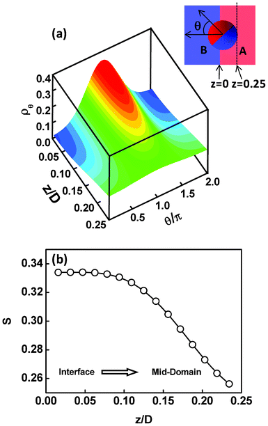 | ||
| Fig. 3 (a) Volume fractions ρθ of the Janus nanoparticles at various angles θ as a function of the displacement z/D normal to lamella. The parameter is RJ = 0.6Rg. The insert at the top right corner shows the sketch of the definition of angle θ (noting that for the intuitional illustration the schematic Janus nanoparticles are spherical, although the SCFT model looks like a dumbbell). (b) Order parameters S as a function of the displacement z/D normal to lamella. The z/D = 0 and z/D = 0.25 correspond to the interface and middle A domain, respectively. | ||
The effect of the nanoparticle size on the angular distribution and orientational ordering of the Janus nanoparticles can be further viewed from Fig. 4. The results provided are restricted to the situation at the interface. As shown in Fig. 4a, the angular distributions are nearly uniform as the nanoparticle is smaller. With increasing the RJ, the angular distribution becomes narrower. At much larger values of RJ, the angular distributions exhibit a sharp peak around θ = π. The results reveal that the Janus nanoparticles become more highly-oriented as the nanoparticle size increases. This can also be found from the calculation of the order parameters. As shown in Fig. 4b, the order parameter S first slowly increases to about 0.3, then rapidly increases to about 0.8, and finally slowly increases to about 0.88, as the RJ value increases. From these results, we learned that the Janus nanoparticles at the interface are freely oriented at smaller size and highly oriented at larger size.
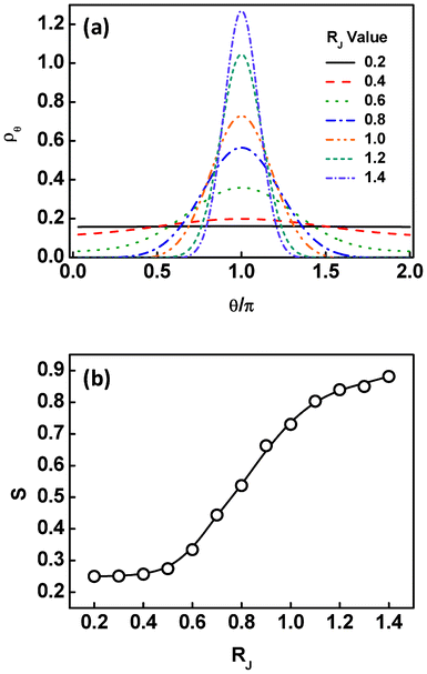 | ||
| Fig. 4 (a) Volume fraction ρθ of the Janus nanoparticles at the interface as a function of the angles θ at different sizes of the Janus nanoparticles. (b) Order parameters of the Janus nanoparticles at the interface as a function of the nanoparticle size RJ. | ||
The change of the displacement and orientation of the Janus nanoparticles has a marked effect on the lamellar spacing. Fig. 5 shows the lamellar spacing as a function of the size of the Janus nanoparticles for the Janus nanoparticles in lamellar scaffold. As shown in Fig. 5, the response of the lamellar spacing to the variation of the nanoparticle size is complicated. At smaller values of RJ, the lamellar spacing is about 3.78Rg. As the RJ increases to 0.4Rg, the lamellar spacing is almost unchanged. With further increasing the RJ, the lamellar spacing somewhat decreases and then increases rapidly. When the size of the Janus nanoparticles increases to 1.1Rg, the lamellar spacing shows another decrease and subsequently increases. To clearly view such changes of the lamellar spacing, we provided the representative sketches of the nanocomposites at different stages of RJ (see the insets of the Fig. 5). From above results, we can see that the first decrease of the lamellar spacing occurs when the Janus nanoparticles tend to migrate from the middle domains (see also Fig. 2a), and the second decrease appears when the density of the JA spherical caps are overlapped into a single peak (see also Fig. 2b). When RJ ≈ 1.2Rg (second decrease), the lamellar spacing (4.08Rg) is nearly equal to 4RJ minus the interfacial width ∼0.9Rg, implying that almost all the Janus nanoparticles at the interface are overlapped with the Janus nanoparticles at the neighboring interface.
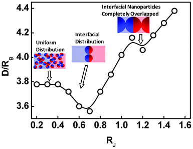 | ||
| Fig. 5 Lamellar spacing D/Rg as a function of the size RJ of the Janus nanoparticles. | ||
The variation of the Janus nanoparticle distributions as a function of the nanoparticle size can be understood by considering the complex interplay of enthalpic and entropic effects. For ease of understanding, we classified the distribution of the Janus nanoparticles in block copolymer scaffolds into three modeled states, which are illustrated in Fig. 6. First, when the translational entropy of the Janus nanoparticles dominates the behavior of the systems, the Janus nanoparticles prefer to disperse uniformly, as shown in Fig. 6a. The Janus nanoparticles may be freely oriented to shield the unfavorable spherical caps from the domain through forming micelles.54 This is the main case for smaller Janus nanoparticles. Second, when the polymeric entropy is dominant, the Janus nanoparticles may be located in the central domains, as shown in Fig. 6b. In this case, the stretching required by the polymer to circumvent the Janus nanoparticles can be effectively reduced. This may be the reason that the distribution of nanoparticle centers shows a peak in the middle domain at smaller size. Third, when the interaction enthalpy determines the position of the Janus nanoparticles, the Janus nanoparticles tend to be attached to the interfaces, as shown in Fig. 6c. Such a distribution can give rise to a decrease of the interaction between dissimilar blocks but higher configurational entropy losses of the block copolymers. This is the case for the larger Janus nanoparticles.
 | ||
| Fig. 6 Sketches of three different distributions of the Janus nanoparticles in the block copolymer scaffolds: (a) distribution favored by translational entropy, (b) distribution favored by polymeric entropy, and (c) distribution favored by interaction enthalpy. | ||
Based on the above analysis, we speculated that the migration of the Janus nanoparticles from uniform state to the interface with increasing the nanoparticle sizes can effectively reduce the interaction enthalpy, accompanied by a sacrifice of the polymeric entropy and translational entropy. To prove this hypothesis, we decomposed the free energy into five contributions, including the enthalpy UP/nkBT between the A and B blocks, the enthalpy UPJ/nkBT between the Janus nanoparticles and block copolymers, the configurational entropic loss −SP/nkB of the diblock copolymers, the translational entropic loss −SJT/nkB of the Janus nanoparticles, and the steric entropic loss −SJS/nkB of the Janus nanoparticles, to examine the enthalpic and entropic changes.
In Fig. 7, the enthalpic and entropic contributions to the free energy are plotted as a function of the Janus nanoparticle sizes. As shown in Fig. 7a, the interaction enthalpies UP/nkBT and UPJ/nkBT decrease, while the configurational entropic loss −SP/nkB increases, as the size of the Janus nanoparticles increases. Meanwhile, the translational entropic loss −SJT/nkB of the Janus nanoparticles shows an increase, as the RJ increases (Fig. 7b). These results are in good agreement with our hypothesis that the migration of the Janus nanoparticles from uniform state to the interface with increasing the RJ decreases the interaction enthalpy and increases the losses of configurational entropy and translational entropy. In addition, it was found that the steric entropic loss −SJS/nkB of the Janus nanoparticles decreases as the size increases, due to the reduced number density of the Janus nanoparticles (inversely proportional to cubic size). It should be noted that, when the RJ increases from 1.1Rg to 1.2Rg, the UP/nkBT and −SP/nkB show an increase and a decrease, respectively. This may be due to the high overlap of the Janus nanoparticles in the middle domains (Fig. 2b).
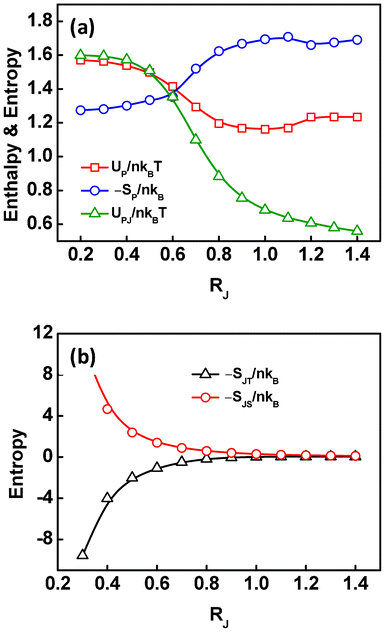 | ||
| Fig. 7 (a) The contributions of interaction enthalpy UPJ/nkBT between the Janus nanoparticles and diblock copolymers, UP/nkBT between the dissimilar diblocks, and configurational entropic loss −SP/nkB of the diblock copolymers to free energy as a function of the size of the Janus nanoparticles. (b) The contributions of the translational entropic loss −SJT/nkB and steric entropic loss −SJS/nkB of the Janus nanoparticles to free energy as a function of the size of the Janus nanoparticles. | ||
Effect of relative size of two spherical caps
The above calculations were performed for the Janus nanoparticles with equal spherical caps in size. In addition to the overall size of the Janus nanoparticles, the change of the relative sizes of two spherical caps (see Fig. 1b) can also cause the distribution changes of the Janus nanoparticles. A representative result is presented in Fig. 8, for the center density distributions and order parameters of the Janus nanoparticles with fixed size of JA spherical cap (RJA = 1.0Rg) and varying sizes of JB spherical cap in the block copolymer scaffold. In the figures, z/D = 0 and z/D = 0.5 correspond to the middle B domain and middle A domain, respectively. As shown in Fig. 8a, the Janus nanoparticles are located near the interface when RJB = RJA = 1.0Rg, because of their higher interfacial activity. With decreasing the RJB, the Janus nanoparticles move away from the interface into the domains preferred by the JA spherical caps. When the RJB is smaller, this trend becomes more pronounced. Moreover, the position at which the maximum density of the nanoparticle center appears shifts from the interface to the preferred A domain, as the RJB decreases. However, the Janus nanoparticles still remain strongly attached to the interface as the RJB changes.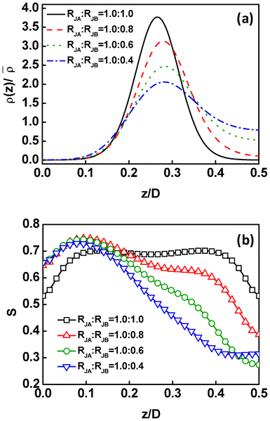 | ||
| Fig. 8 (a) Density distributions ρ(z) of the Janus nanoparticle centers as a function of the displacement z/D normal to the lamella for the Janus nanoparticles with various RJB. The density ρ(z) is normalized by the mean density of the particle centers. (b) Order parameters as a function of the displacement z/D normal to the lamella for the Janus nanoparticles with various RJB. The RJA is fixed as 1.0Rg. The z = 0, z = 0.25, and z = 0.5 correspond to the middle B domain, interface, and middle A domain, respectively. | ||
These results are in qualitative agreement with the experimental observations reported by Kim et al. They prepared gold nanoparticles coated with mixed ligands of PS and P2VP in PS-b-P2VP block copolymers.22 The two mixed ligands can segregate into opposite spherical caps to form the Janus nanoparticles. It was found that the positions of such Janus nanoparticles shift from the interface between PS and P2VP domains to the center of the PS domains by increasing the fraction of PS from 0.80 to 0.92. It should be noted that the P2VP spherical caps become smaller than PS spherical caps with increasing the PS fraction from 0.80 to 0.92. Consistent with the experimental observations, in our study, the Janus nanoparticle are also found to move away from the interface into the polymeric domains as one spherical cap becomes smaller than the other one. This result also agrees with recent theoretical results reported by Kim and Matsen that the Janus nanoparticles shift to the appreciated domain centers as the compositions deviate from the symmetry composition, by implementing a SCFT which is different from the present SCFT/DFT methods, with a multi-coordinate-system scheme.23 They predicted that the particle distributions are more localized at/near the interface than in the domains, as also shown in Fig. 8a.
Fig. 8b shows the effect of the relative sizes of the spherical cap on the orientational order parameters of the Janus nanoparticles. For equal RJB and RJA, the order parameters are symmetric about the interface (z/D = 0.25). The order parameters persist at higher values for broad range of z/D, and decrease when approaching the central domains. When the RJB decreases, the order parameters become asymmetric about the interface. The maximum order parameters appear in the B domains, where the smaller JB spherical caps prefer. In addition, the order parameters decrease more rapidly when the position increases from about z/D = 0.1. Such a phenomenon can be explained as follows. The Janus nanoparticles are able to form micelles (lower orientational order parameter) in order to shield the spherical caps from their dissimilar domains.54 In the polymeric domain, the Janus nanoparticles with smaller dissimilar spherical caps easily form micelles that are covered by larger similar spherical caps, and vice versa. As a consequence, the order parameters for the Janus nanoparticles with smaller RJB decrease rapidly in/near the A domain, and remain a higher value in the B domains.
While turning our attention to the Janus nanoparticles with larger sizes (RJA = RJB), we discovered an interesting phenomenon as the interaction strength between the Janus nanoparticles and block copolymers is higher than that between the A and B blocks, i.e, χAJBN = χBJAN > χABN. Fig. 9a shows the structures obtained for the Janus nanoparticles with χAJBN = χBJAN = 30 in the block copolymer scaffolds with χABN = 20. As shown in Fig. 9a, the Janus nanoparticles are segregated at the interface of the block copolymer scaffold, forming a hierarchical cylinder-in-lamella structure. Moreover, the Janus nanoparticles are only anchored at one selective interface between the A and B domains and line up into a ferro-like arrangement, different from the case in Fig. 2. In fact, the cylinder-in-lamella only appears when the size of the Janus nanoparticles is larger, and the Janus nanoparticle distributions at the interface can change back into the homogeneous states as the nanoparticle size decreases.
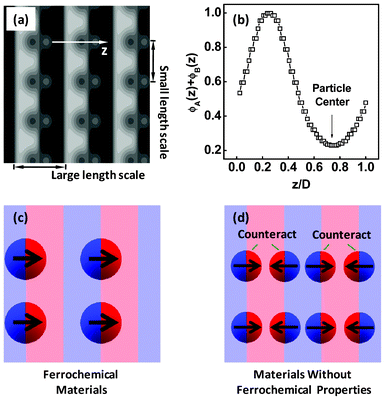 | ||
| Fig. 9 (a) Equilibrium structures formed by the Janus nanoparticles with RJ = 1.4Rg in symmetric diblock copolymers. The interaction strengths are χAJBN = χBJAN = 30 and χABN = 20. (b) One-dimensional density profile of total A and B blocks as a function of the displacement z/D normal to lamella. (c) Sketch of a ferrochemical material containing the dipolar Janus nanoparticles and block copolymers, where the Janus nanoparticles are lined up in a ferro-like arrangement. (d) Sketch of the materials without ferrochemical properties, where the polarity was counteracted at macroscopic length scales due to the centrosymmetric distribution of the dipolar Janus nanoparticles. | ||
At this point, it should be mentioned that the excluded-volume effect may be not treated very accurately in the SCFT/DFT method, since the present method allows the polymers to penetrate the space occupied by the Janus nanoparticles. However, from the Fig. 9b, we found that the polymer density in the particle centers is very small, implying that the polymers are almost excluded from the Janus nanoparticles. From this viewpoint as well as the consistency with available findings, we rather think the present calculations can capture the essential feature of the self-assembly of Janus nanoparticles in block copolymer scaffolds. Indeed, a more accurate treatment of the excluded-volume effect may further improve the prediction power of the method. Recently, Kim and Matsen proposed a SCFT approach for studying the positioning of Janus nanoparticles in block copolymer scaffolds, by treating the nanoparticles as an impenetrable spherical particle.23 Therefore, the exclude-volume problem was overcome in their approach. However, their approach ignored the particle–particle interactions, since an ideal gas limit was assumed. This has limited a further study for multi-particle systems. In contrast, the present SCFT/DFT approach is suited for the study of the multi-particle system. To solve both these problems, i.e., excluded-volume and multi-particle problems, a development of new approach is required in future. For example, the approach can be developed by treating the particles as rigid bodies with smooth profiles and solving the equations of motion that couple the hydrodynamics and rigid-body dynamics (or as in the work carried out by Sides et al.).55,56 This will be a future topic for predicting the behavior of Janus nanoparticles more accurately.
Another aspect we have to mention is that, although the present work is focused on the lamellar scaffolds of the block copolymers, the morphology of the block copolymer scaffolds should have an effect on the distributions of the Janus nanoparticles, especially for the Janus nanoparticles with larger sizes. For example, for cylindrical scaffolds formed by the block copolymers, the symmetric Janus nanoparticles may not stick to the interface, because the Janus nanoparticles become easily overlapped in the minor cylindrical domains and the exclude-volume effect would drive them away from the interface (or even a morphological transformation).
The nanocomposites with the structures shown in Fig. 9a may be applied to the design of ferrochemical materials with interesting nonlinear optical, ferroelectric, or ferromagnetic properties.57 In the noncentrosymmetric structures shown in Fig. 9a, the Janus nanoparticles line up side by side into a ferro-like arrangement along one direction, as illustrated in Fig. 9c. As a result, the macroscopic materials can exhibit ferroelectric/ferromagnetic properties if the electric/magnetic dipoles are carried by the Janus nanoparticles. However, such ferrochemical materials can only be prepared from nanocomposites with larger Janus nanoparticles. When the Janus nanoparticles are smaller, the distribution of Janus nanoparticles becomes centrosymmetric. In this case, the Janus nanoparticles stack in a head-to-tail/antiferro-like arrangement in every structural period, and therefore the polarity is counteracted at macroscopic length, as illustrated in Fig. 9d. This results in a macroscopic material without ferroelectric/ferromagnetic properties. We here offered a general theoretical model for advanced materials with ferrochemical properties.
Conclusion
The self-consistent field theory/density functional theory was extended to study the equilibrium distribution of the Janus nanoparticles in block copolymer scaffolds. It was discovered that the capability of the Janus nanoparticles to stick to the interface is dependent on their sizes. With increasing the nanoparticle size, the Janus nanoparticles change from an almost uniform distribution to aggregation at the interface. As the nanoparticle sizes are much larger, the Janus nanoparticles become strongly attached to the interface. At the interface, the Janus nanoparticles are highly oriented, leading to a higher value of the orientational order parameters. The order parameters of the Janus nanoparticle at the interface increase as the nanoparticle size increases. While in/near the middle domain, the Janus nanoparticles are freely oriented, and therefore they form micelle structures to shield the unfavorable spherical caps from the polymeric domains. In addition, the change of the relative size of the spherical caps can also incur a variation of the Janus nanoparticle distributions. When one of the spherical caps becomes smaller, the Janus nanoparticles migrate to the domain that the larger spherical caps like, but still show a dominating distribution near the interface. We anticipated that the present study could provide valuable information for designing and creating structured nanocomposites.Acknowledgements
This work was supported by National Natural Science Foundation of China (50925308, 21234002), Key Grant Project of Ministry of Education (313020) and National Basic Research Program of China (No. 2012CB933600). Support from project of Shanghai municipality (10GG15) is also appreciated.References
- A. C. Balazs, Curr. Opin. Colloid Interface Sci., 2000, 4, 443–448 CrossRef.
- Y. Lin, A. Böker, J. He, K. Sill, H. Xiang, C. Abetz, X. Li, J. Wang, T. Emrick, S. Long, Q. Wang, A. C. Balazs and T. P. Russell, Nature, 2005, 434, 55–59 CrossRef CAS.
- A. J. Schultz, C. K. Hall and J. Genzer, Macromolecules, 2005, 38, 3007–3016 CrossRef CAS.
- A. Haryono and W. H. Binder, Small, 2006, 5, 600–611 CrossRef.
- A. C. Balazs, T. Emrick and T. P. Russell, Science, 2006, 314, 1107–1110 CrossRef CAS.
- V. Ganesan, J. Polym. Sci., Part B: Polym. Phys., 2008, 46, 2666–2671 CrossRef CAS.
- H. Kang, F. A. Detcheverry, A. N. Mangham, M. P. Stoykovich, K. Ch. Daoulas, R. J. Hamers, M. Müller, J. J. de Pablo and P. F. Nealey, Phys. Rev. Lett., 2008, 100, 148303 CrossRef.
- W. U. Huynh, J. J. Dittmer and A. P. Alivisatos, Science, 2002, 295, 2425–2427 CrossRef CAS.
- V. V. Pokropivnyi, Powder Metall. Met. Ceram., 2002, 41, 264–272 CrossRef CAS.
- C. Xu, K. Ohno, V. Ladmiral, D. E. Milkie, J. M. Kikkawa and R. J. Composto, Macromolecules, 2009, 42, 1219–1228 CrossRef CAS.
- S. Jiang, Q. Chen, M. Tripathy, E. Luijten, K. S. Schweizer and S. Granick, Adv. Mater., 2010, 22, 1060–1071 CrossRef CAS.
- A. Walther and A. H. E. Müller, Soft Matter, 2008, 4, 663–668 RSC.
- Y. Liu, V. Abetz and A. H. E. Müller, Macromolecules, 2003, 36, 7894–7898 CrossRef CAS.
- A. Walther, X. Andre, M. Drechsler, V. Abetz and A. H. E. Müller, J. Am. Chem. Soc., 2007, 129, 6187–6198 CrossRef CAS.
- R. Erhardt, A. Bo1ker, H. Zettl, H. Kaya, W. Pyckhout-Hintzen, G. Krausch, V. Abetz and A. H. E. Müller, Macromolecules, 2001, 34, 1069–1075 CrossRef CAS.
- A. Walther, M. Drechsler, S. Rosenfeldt, L. Harnau, M. Ballauff, V. Abetz and A. H. E. Müller, J. Am. Chem. Soc., 2009, 131, 4720–4728 CrossRef CAS.
- R. F. Shepherd, J. C. Conrad, S. K. Rhodes, D. R. Link, M. Marquez, D. A. Weitz and J. A. Lewis, Langmuir, 2006, 22, 8618–8622 CrossRef CAS.
- N. Virgilio and B. D. Favis, Macromolecules, 2011, 44, 5850–5856 CrossRef CAS.
- J. W. O. Salari, F. A. M. Leermakers and B. Klumperman, Langmuir, 2011, 27, 6574–6583 CrossRef CAS.
- P. G. de Gennes, Rev. Mod. Phys., 1992, 64, 645–648 CrossRef.
- A. Walther, K. Matussek and A. H. E. Müller, ACS Nano, 2008, 6, 1167–1178 CrossRef.
- B. J. Kim, J. Bang, C. J. Hawker, J. J. Chiu, D. J. Pine, S. G. Jang, S.-M. Yang and E. J. Kramer, Langmuir, 2007, 23, 12693–12703 CrossRef CAS.
- J. U. Kim and M. W. Matsen, Phys. Rev. Lett., 2009, 102, 078303 CrossRef.
- L.-T. Yan, N. Popp, S.-K. Ghosh and A. Böker, ACS Nano, 2010, 4, 913–920 CrossRef CAS.
- R. B. Thompson, Phys. Rev. E, 2006, 74, 041501 CrossRef.
- R. B. Thompson, Phys. Rev. E, 2006, 73, 020502 CrossRef CAS.
- R. B. Thompson, J. Y. Lee, D. Jasnow and A. C. Balazs, Phys. Rev. E, 2002, 66, 031801 CrossRef.
- R. B. Thompson, V. V. Ginzburg, M. W. Matsen and A. C. Balazs, Science, 2001, 292, 2469–2472 CrossRef CAS.
- J. Y. Lee, R. B. Thompson, D. Jasnow and A. C. Balazs, Macromolecules, 2002, 35, 4855–4858 CrossRef CAS.
- L. Zhou and Y. Ma, J. Phys.: Condens. Matter, 2008, 20, 095006 CrossRef.
- L. Zhang, J. Lin and S. Lin, Macromolecules, 2007, 40, 5582–5592 CrossRef CAS.
- X. Zhu, L. Wang, J. Lin and L. Zhang, ACS Nano, 2010, 4, 4979–4988 CrossRef CAS.
- G. H. Fredrickson, In The Equilibrium Theory of Inhomogeneous Polymers, Oxford University Press, Oxford, U.K., 2006 Search PubMed.
- M. W. Matsen and R. B. Thompsom, J. Chem. Phys., 1999, 111, 7139–7146 CrossRef CAS.
- M. W. Matsen and M. Schick, Phys. Rev. Lett., 1994, 72, 2660–2663 CrossRef CAS.
- R. Wang, W. Li, Y. Luo, B. Li, A.-C. Shi and S. Zhu, Macromolecules, 2009, 42, 2275–2285 CrossRef CAS.
- R. Jiang, Q. Jin, B. Li, D. Ding, R. A. Wickham and A.-C. Shi, Macromolecules, 2008, 41, 5457–5465 CrossRef CAS.
- X. Ye, T. Shi, Z. Lu, C. Zhang, Z. Sun and L. An, Macromolecules, 2005, 38, 8853–8857 CrossRef CAS.
- P. Chen, H. Liang and A.-C. Shi, Macromolecules, 2008, 41, 8938–8943 CrossRef CAS.
- L. Zhang and J. Lin, Macromolecules, 2009, 42, 1410–1414 CrossRef CAS.
- L. Wang, J. Lin and L. Zhang, Macromolecules, 2010, 43, 1602–1609 CrossRef CAS.
- E. W. Cochran, C. J. Garcia-Cervera and G. H. Fredrickson, Macromolecules, 2006, 39, 2449–2451 CrossRef CAS.
- H. Yu, M. Chen, P. M. Rice, S. X. Wang, R. L. White and S. Sun, Nano Lett., 2005, 5, 379–382 CrossRef CAS.
- N. Glaser, D. J. Adams, A. Böker and G. Krausch, Langmuir, 2006, 22, 5227–5229 CrossRef.
- Z. Meng, C. Xue, L. Lu, B. Yuan, X. Yu, K. Xi and X. Jia, J. Colloid Interface Sci., 2011, 356, 429–433 CrossRef CAS.
- F. Drolet and G. H. Fredrickson, Phys. Rev. Lett., 1999, 83, 4317–4320 CrossRef CAS.
- V. Ganesan and G. H. Fredrickson, Europhys. Lett., 2001, 55, 814–820 CrossRef CAS.
- L. Wang, L. Zhang and J. Lin, J. Chem. Phys., 2008, 129, 114905 CrossRef.
- G. Tzeremes, K. Ø. Rasmussen, T. Lookman and A. Saxena, Phys. Rev. E, 2002, 65, 041806 CrossRef CAS.
- K. Ø. Rasmussen and G. Kalosakas, J. Polym. Sci., Part B: Polym. Phys., 2002, 40, 1777–1783 CrossRef CAS.
- V. Eyert, J. Comput. Phys., 1996, 124, 271–285 CrossRef.
- R. B. Thompson, K. Ø. Rasmussen and T. Lookma, J. Chem. Phys., 2004, 120, 31–34 CrossRef CAS.
- Y. Bohbot-Raviv and Z.-G. Wang, Phys. Rev. Lett., 1999, 83, 4317–4320 CrossRef.
- L. Hong, A. Cacciuto, E. Luijten and S. Granick, Nano Lett., 2006, 6, 2510–2514 CrossRef CAS.
- Y. Nakayama, K. Kim and R. Yamamoto, Eur. Phys. J. E, 2008, 26, 361–368 CrossRef CAS.
- S. W. Sides, B. J. Kim, E. J. Kramer and G. H. Fredrickson, Phys. Rev. Lett., 2006, 96, 250601 CrossRef.
- D. Ausserré, Macromolecules, 2012, 45, 2478–2484 CrossRef.
| This journal is © The Royal Society of Chemistry 2012 |
