Electrospinning and additive manufacturing: converging technologies
Paul D.
Dalton
*,
Cédryck
Vaquette
,
Brooke L.
Farrugia
,
Tim R.
Dargaville
,
Toby D.
Brown
and
Dietmar W.
Hutmacher
*
Institute for Health and Biomedical Innovation, Queensland University of Technology, 60 Musk Avenue, Kelvin Grove 4059, Australia
First published on 22nd October 2012
Abstract
A well-engineered scaffold for regenerative medicine, which is suitable to be translated from the bench to the bedside, combines inspired design, technical innovation and precise craftsmanship. Electrospinning and additive manufacturing are separate approaches to manufacturing scaffolds for a variety of tissue engineering applications. A need to accurately control the spatial distribution of pores within scaffolds has recently resulted in combining the two processing methods, to overcome shortfalls in each technology. This review describes where electrospinning and additive manufacturing are used together to generate new porous structures for biological applications.
 Paul Dalton | Paul Dalton studied multidisciplinary science at Curtin University in Perth, Australia, and researched ophthalmic biomaterials at the Lions Eye Institute during his PhD. After graduating in 1999, he spent three years at the University of Toronto, followed by an Alexander Von Humboldt Fellowship at RWTH-Aachen, Germany, where he pioneered melt electrospinning in the biomedical sciences. In 2006 he received a Wellcome Trust Fellowship to perform experimental spinal cord surgery in Southampton (UK). From 2009 he continued in vivo research at Shanghai Jiao Tong University, China, while developing melt electrospinning at QUT, where he is an adjunct associate professor. |
 Cédryck Vaquette | Cédryck Vaquette graduated from the European School of Materials Science in 2003 and completed his PhD in Tissue Engineering at the Laboratoire d'Energetique et de Mécanique Théorique et Appliquée. After graduating in 2008 he moved to the Australian Institute for Bioengineering and Nanotechnology at University of Queensland until 2010, when he joined the Institute of Health and Biomedical Innovation at QUT where he is developing biphasic structures for periodontal tissue engineering. His research interests are electrospinning, tissue engineering for orthopaedic applications and bone regeneration. |
 Brooke Farrugia | Brooke Farrugia received her Bachelors in Chemical Engineering and a Masters in Biomedical Engineering in 2006 from the University of New South Wales, Australia. She completed her PhD under the supervision of Prof. Laura Poole-Warren in 2010. Since then, she has conducted her postdoctoral research at Queensland University of Technology as a member of an interdisciplinary team consisting of polymer chemists, cell biologists, engineers, and mathematicians, focusing on research into tissue repair and regeneration. |
 Tim Dargaville | Tim Dargaville completed his PhD in polymer chemistry in 2003 at the University of Queensland under the supervision of David Hill. From 2003–2005 he was a research scientist at Sandia National Laboratories in Albuquerque, New Mexico, and in 2006 returned to Australia to take up a position at QUT. He is now a senior lecturer with research interests in novel polymers for biomaterial and sensor applications, especially related to wound healing. He is the recipient of a Queensland ‘Smart State’ Fellowship and is leader of the Tissue Repair and Regeneration program at QUT. |
 Toby Brown | Toby Brown is an APA scholarship PhD student at the Institute of Health and Biomedical Innovation at QUT, after graduating in Engineering (Medical Honours First Class) in 2010. He was awarded an Australian Endeavour Research Fellowship and an ATN/DAAD grant for 2012 to continue his thesis work in the Department for Functional Materials in Medicine and Dentistry, University of Wuerzburg, Germany, with Juergen Groll. His research interest focuses on developing new methods to design and fabricate tissue engineering scaffolds based on the process of melt electrospinning. |
 Dietmar W. Hutmacher | Dietmar W. Hutmacher is a multidisciplinary biomedical engineer and Chair of Regenerative Medicine at QUT. An educator, inventor, and a creator of new intellectual property opportunities, he obtained his MBA from Henley in 1999 and his PhD from the National University of Singapore in 2001. His successful research is through concerted and integrated leadership with colleagues in engineering (tissue engineering, biomaterials science, computational modelling, chemistry, nanotechnology), life sciences (molecular cell and developmental biology, medicine, stem cell research, genomics, proteomics, bioinformatics), and applied clinical research (orthopaedics, plastic surgery, radiology). He is one of the few academics with developed concepts from the bench to the bedside. |
Introduction
A reliable and controlled process for the design and manufacture of scaffolds is one of the key elements in furthering tissue engineering (TE) and regenerative medicine research.1 There are already numerous scaffold fabrication techniques available including solvent casting,2 particulate leaching,3 gas foaming, solution electrospinning,1 phase separation4 and freeze drying.5 Each processing method has its disadvantages, though, which are predominantly regarding the ability to precisely control scaffold pore size, geometry and interconnectivity.5 Furthermore, such scaffold fabrication techniques often use organic solvents as part of the process to dissolve synthetic polymers or porogens,6,7 which leads to concerns regarding toxicity. Even with many different types of scaffolds available, there is still a need to develop new design and manufacturing approaches that allow a systematic change to three dimensional (3D) pore architecture.This challenge of accurately controlling the spatial distribution of pores and structures within the scaffold has been met somewhat by additive manufacturing (AM) processes.8,9 This is a broad term for an increasing number of techniques in which complex structures are constructed in a layer-by-layer manner according to computer aided design. Although providing precise control over scaffold architecture, many current AM approaches involving biocompatible/degradable polymers lack the smaller filament resolution required to produce scaffolds for a range of tissues. AM approaches commonly used within TE include fused deposition modeling (FDM),10 selected laser sintering,11,12 stereolithography13 and inkjet printing.14,15
An alternative processing technique for the fabrication of scaffolds for TE applications is solution electrospinning,7,16,17 which is generally not considered as an AM technique due to the dynamic and chaotic nature of fiber deposition. Several groups including ourselves have used patterned collectors18,19 as well as rotating mandrels20,21 to better control and predict the deposition behavior of solution electrospun fibers, however this is not an AM approach. Therefore, both AM and electrospinning have independently attracted exponentially increasing interest in the design and fabrication of scaffolds over the past fifteen years. In our opinion, shortfalls within each technology could be solved by combining the two processing methods into one generic concept to design and fabricate scaffold morphologies unseen until now. In general, the limitations of AM include lower resolution fabrication limits, while electrospinning is unable to accurately reproduce structured 3D scaffolds.
Here we review papers where electrospinning (from both solution and melt) is used with AM principles. While not always produced for TE applications, combining aspects of electrospinning with AM can have a significant effect on future scaffold design. We also briefly describe bimodal and multiphasic TE scaffolds, as this is an emerging area that is already adopting both electrospinning and AM. We spend a significant time outlining melt electrospinning writing as an AM approach and describe the different TE scaffolds published using this technique. While journal articles describing melt electrospinning are limited (less than 0.5% of the total electrospinning literature),22 the more predictable nature of the electrified molten jet makes this process amenable to AM approaches.
Summary of electrospinning
Electrospinning relies on an electrified viscous fluid (solution or melt) jet being drawn through the air towards a collector which is at a different electric potential. If there are sufficient molecular entanglements in the polymer, the jet does not break up into droplets due to Raleigh instabilities,23 and deposits continuously to create a non-woven mesh of fibers. The polymer concentration and molar mass influence the level of entanglement of solutions, while droplet breakup of electrified melts is mainly subject to the molar mass.After the electrified jet leaves the spinneret it is initially stable and travels directly towards the collector. The surface charge density of the liquid (which caused the ejection of the jet from the droplet) again increases with decreasing distance to the collector, and “twists” the jet, resulting in bending instabilities and a second zone of fiber formation.24 In this zone, the instabilities in the charged jet's path cause it to spiral or “whip”: where under the influence of the electric field it rapidly accelerates laterally to the flight path, leading to further stretching.
As the electrified jet passes through the air, the solvent evaporates or the molten polymer cools, depending on the mode of electrospinning (solution or melt). With solution electrospinning, there may be different levels of instability, and as such it is a highly dynamic process resulting in technical challenges to control the deposition of fibers so that they result in defined structures.25 Due to an inherent higher viscosity and typically lower conductivity, melt electrospinning can generate fibers without the dynamic bending of the electrified jet. Two studies in independent laboratories with different polymers showed that the direct path of an electrified melt electrospun jet is particularly long, with instabilities just at the collector surface or not at all.26,27 This phenomenon can be utilized in AM, as we will discuss later.
Since electrospinning requires a charged fluid jet to be drawn over a distance to a collector at a different electric potential, this allows limitless flexibility in the configuration of the collector, so long as the electric field gradient is maintained. There are numerous fiber collection techniques devised to improve the orderly placement of electrospun fibers, including the use of structured electro-conductive collectors,18,28 dynamic mechanical devices (e.g. rotating devices),29 fiber deposition onto liquid,30 manipulation of the electric field31 and guiding fibers across voids.32,33 None of these methods, however, offers the precise location of fibers, and thus control over scaffold architecture, as AM processes do. Further, charge accumulation with the deposited fibers restricts the number of layers which remain bound as one coherent structure. Thus, due to the scale of the fibers, the thickness of scaffolds achievable using these methods is limited to effectively two dimensions; even though the use of a secondary electrode elicits the deposition of thicker scaffolds, their thickness is still limited to 3–4 mm.34
Solution electrospun meshes have tightly packed fibers with a low porosity that is not readily controlled. This results in cells being unable to infiltrate the scaffolds and instead only grow on top of the electrospun fiber surface. The use of structured collectors is one simple way to generate open pore sizes within electrospun scaffolds. Zhang et al. and others found that structured collectors could greatly affect the resulting structures of the electrospun mats – essentially acting as a patterned template to influence electrospun fiber collection.18,19 Neves et al. also patterned solution electrospun meshes with shaped collectors with specific dimensions and designs, and evaluated the structures of fibers for biomedical applications.35 Wang et al. also found that electrospun fabrics with tailored architectures and patterns have potential for TE applications by inducing ordered cellular organization36 and locally increasing cell infiltration.18 Although structured collectors allow porous electrospun scaffolds, the process still relies on a chaotic deposition of fibers, and their accurate placement is fixed to the collector used in the experiments.
Bimodal and multiphasic scaffolds for TE
The combination of AM and electrospinning was first described in an effort to make bimodal scaffolds, where both micro- and nano-scale elements are combined. This promoted cell invasion while retaining nanofibrous elements. In 2008, three papers by Moroni et al., Kim et al. and Park et al.—all from different groups—described an FDM process that was interrupted between each layer to deposit an electrospun fiber mesh (Fig. 1).37–39 Even though the two separate procedures of FDM and electrospinning are simply combined, these bimodal scaffolds are the first instances where the two techniques are used to form a single product. The resultant constructs contained large pores, while the electrospun fibers provided suitable structures for cell adhesion; effectively increasing the surface area available for the penetrating cells to attach to. Another paper combined FDM and electrospinning to make tubular structures for vascular TE.40 Here the FDM fibers provided sufficient mechanical strength, while the electrospun material was a nano-structured substrate for improved adhesion.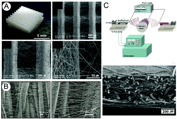 | ||
| Fig. 1 Examples of bimodal scaffolds produced by combining solution electrospinning with (A) FDM, (B) melt spinning and (C) melt electrospinning to produce both nano- and micro-fibrous elements within a single TE construct. Figure (A) is reproduced from ref. 37, (B) from ref. 43 and (C) from ref. 42, all with permission. | ||
The larger structural component in a bimodal scaffold does not need to be produced by AM.41–44 For example, the different fiber diameters obtained from solution and melt electrospinning were used by Kim et al. to produce bimodal scaffolds. The simultaneous electrospinning of a PLGA melt (which produced micron-diameter fibers of 28.0 ± 2.6 μm) and a PLGA solution (which produced sub-micron diameter fibers of 530 ± 240 nm) onto a rotating mandrel produced a thick cell invasive scaffold containing both sub-micron and micron diameter elements (Fig. 1C).42 In another paper following bimodal scaffold principles, a tubular construct was manufactured by melt spinning larger fibers and using solution electrospun fibers as the smaller element (Fig. 1B).43
While bimodal scaffolds contain microfibrous and nanofibrous elements distributed throughout the architecture, multiphasic scaffolds contain different regions of pore size and porosity. These two trends in scaffold fabrication have come about due to the complexity of the tissues and organs that scientists are aiming to repair or replace with TE, and engineers are bound to develop even more elaborate structures in the future. Multiphasic scaffolds have different components that elicit successful regeneration of tissue interfaces, by providing an adequate environment for the different cells types in order to form a new functional tissue interface.
Our group has developed a multiphasic scaffold composed of a FDM scaffold and solution electrospun membrane to promote ectopic periodontal regeneration in an athymic rat subcutaneous model.45 The solution electrospun scaffold acted as a support membrane for permitting the adhesion of a periodontal ligament fibroblast cell sheet, while the FDM scaffold enabled space maintenance for bone regeneration to occur and biomechanical stability. Our group has also developed similar structures, utilizing a melt electrospun membrane for the same purpose of regenerating the periodontium complex (Fig. 2). In this strategy, the FDM scaffold (bone compartment) acts as a support for bone ingrowth. The melt electrospun scaffold (periodontal compartment), seeded with cells of interest (e.g. periodontal ligament cells or mesenchymal stem cells), enabled the formation of periodontal ligament fibers and the insertion of these fibers into newly formed cementum on the root surface. Further to this strategy, bone formation can be stimulated by the incorporation of bioactive molecules, such as bone morphogenic protein-7 (BMP-7) carried by a hydrogel injected into the bone compartment (Fig. 2). This concept was translated in our group as a proof of principle study, into which the biphasic scaffold was loaded with BMP-7 in the bone compartment and seeded with periodontal ligament cells in the periodontal compartment. It was then placed onto a dentin block and subcutaneously implanted in athymic rats for 8 weeks. The design of this biphasic scaffold permitted a high level of bone formation (see Fig. 2C–E) in the adjacent compartment, without any trace of mineralization in the periodontal compartment. The melt electrospun scaffold acted as a barrier for the hydrogel loaded with BMP, so that the soft ligamentous tissue would not be affected by the release of the drug (see Fig. 2F).
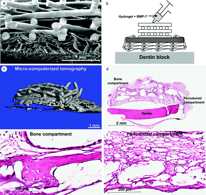 | ||
| Fig. 2 Biphasic scaffold composed of a FDM and a melt electrospun scaffold for periodontal regeneration. (A) Morphology of the cross-section of the biphasic scaffold (SEM), (B) description of the strategy utilized in our proof of principle study, (C) 3D reconstruction of the mineralization construct 8 weeks post-implantation, and (D)–(F) histological analysis of the bone and periodontal compartment. Courtesy of S. Ivanovski, S. Hamlet and C. Vaquette from unpublished data. | ||
Electrospinning is therefore being combined with other AM approaches to produce bimodal or multiphasic scaffolds. While the smaller scale elements are usually produced with solution electrospinning, these could also be produced using melt electrospinning and combined with an AM approach such as FDM. Either way, combining different manufacturing processes is an effective approach to create scaffolds with high architectural complexity that more closely fulfill the requirements for the majority of TE applications.
Solution electrospinning as an AM approach
Even though the first demonstration of direct writing with solution electrospinning was reported a decade ago, there are currently only a handful of such solution electrospinning fiber collection approaches described in the literature. Scanning tip electrospinning,46 near-field electrospinning47 and high precision deposition electrospinning48 all used an automated x–y stage and short collection distances to show predictable control over the location of sub-micron fibers. Scanning tip and near-field electrospinning involve dipping a fine conductive tip into a polymer solution to supply the polymer as a droplet. The polymer droplet approach in these processes limits the total length of nanofiber deposition, and fiber thickness is inevitably non-uniform because the polymer droplet is consumed during the process. Therefore, these techniques are limited to extremely small amounts/areas of deposition, rendering them unsuitable as a method to develop a 3D construct with significant volume. Chang et al. described a more continuous approach, with a near field electrospinning technique using a 200 μm diameter capillary that was constantly fed by a polymer solution.49 This method permitted deposition over a large area (4 × 4 cm2) of a 108 m long fiber in a relatively well controlled fashion. Despite the high relevance of depositing nano-fibers in an orderly manner, the overall throughput of this technique was extremely small, of the order of 0.7 μg polymer per hour. Interestingly, the Taylor cone was initiated by mechanically piercing the pendant drop below a critical voltage so that the droplet is not rapidly depleted. Another technique called high precision deposition electrospinning also used a small diameter capillary (50 μm inner diameter) to produce a continuous system using collector distances as short as 1 mm.48Another approach involved electrospinning a PCL methylene chloride/dimethyl formamide solution into a 5% PEO coagulation bath, using a translating stage to control the deposition of the PCL solution (Fig. 3).50 After washing in deionized water, the scaffold had a porosity of 78%, and the scaffold struts were 205 ± 61 μm in diameter. The scaffold filament surface was quite roughened compared to a typical FDM-formed scaffold, due to involving the precipitation of a polymer solution in a coagulant bath. Osteoblast activity and mineralization was greater than for FDM-produced scaffolds with similar dimensions, perhaps due to the surface roughness.
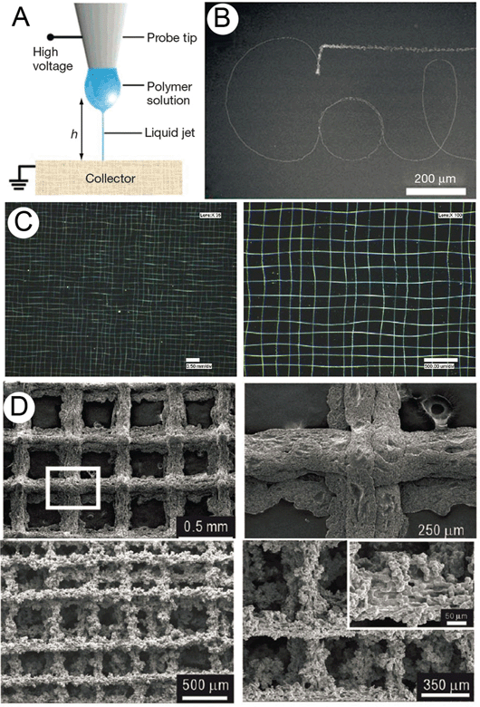 | ||
| Fig. 3 Solution electrospun fibers produced in a direct writing mode. One of the first demonstrations of electrospinning as an AM approach, “scanning tip electrospinning” (A) used short collection distances and small quantities of polymer solution deposited onto an atomic force microscope tip. This work was followed by Sun et al., who termed their process “near-field electrospinning” (B). Hellmann et al. produced even more complex structures, shown in (C). Recent work with coagulation baths precipitated out relatively large struts of PCL in another AM approach (D). In this instance, the benefit over FDM is the surface roughness, which promoted better compatibility with cells. Figure (A) was reproduced with permission from Sun et al., Nanoletters, 6, 839. Copyright 2006 American Chemical Society.47 Figure (B) is reproduced from ref. 49, C from ref. 48 and (D) from ref. 50, all with permission. | ||
Controlling the fiber deposition of solution electrospun fibers without coagulation baths or short gaps is also demonstrated by Lee et al.51 In this approach, a cylindrical side electrode is used in combination with a translating sharp tip that sits below a thin collector (Fig. 4). While the collector remains stationary, it is the translating sharp tip below the collector that controls deposition. An electrospun fiber is therefore produced in the conventional sense that the electrified jet passes through the air for significant distances to permit solvent evaporation. The resulting fibers are sub-micron in diameter and overall have a consistent morphology and uniform fiber diameter. A straight fiber could be drawn on the surface of the collector, although the translation speeds of the tip were relatively high at 50 cm s−1. However, the structures collected were complex and supported 3T3 fibroblast adhesion.
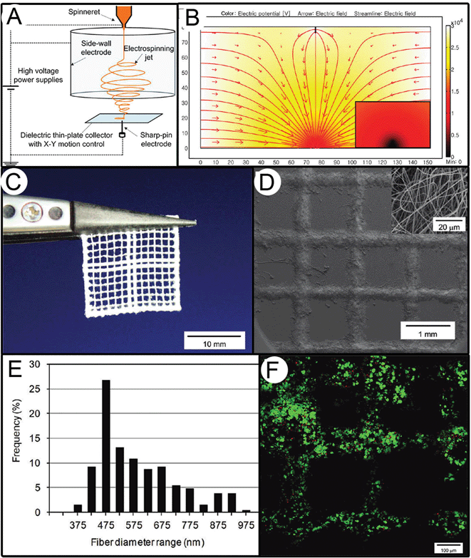 | ||
| Fig. 4 Solution electrospinning in a direct writing mode based on work by Lee et al.51 In this configuration, shown in (A), the jet is controlled by a side-walled electrode, in combination with a moving sharp pin electrode beneath a thin-plate collector. The result is a controlled electrical field (B) that allows direct writing of structures with an example shown in (C) and magnified in an SEM image in (D). The diameter distribution (E) is typical for such electrospun fibers, and (F) supports the survival of 3T3 cells, as shown with the live-dead stain. Figures reproduced with permission from Lee et al., Langmuir, 28, 7267. Copyright 2006, American Chemical Society.51 | ||
Solution electrospinning is greatly influenced by the use of solvents and many of the AM approaches use very short collector distances to minimize electrified jet instabilities.46–49 The dynamic nature of the electrified jet is due to both low surface tensions of polymer solutions combined with high surface charges usually contributed by the solvent. The jet instabilities in solution electrospinning are the reason that the process generates nanofibers, yet it makes their deposition difficult to control. Within TE, there are also issues of cell toxicity due to residual solvent (more important for translation into the clinic) as well as solvent accumulation. The use of volatile, toxic solvents means that cells/tissues cannot be put in contact with solution electrospun materials without full solvent removal. To contrast this last point with melt electrospinning, a 2005 study showed that melt electrospun fibers could be deposited directly onto cells, without affecting their viability.52 Using organic solvents requires full extraction prior to biomedical use and therefore limits the full potential of solution electrospinning as part of a 3D scaffold-based TE concept.
Melt electrospinning as an AM approach
It is well known in the scientific community that solution and melt electrospinning are the two general forms of electrospinning. However, the vast majority of solution electrospun fibers are sub-micron in diameter, while melt electrospinning produces microfibers in the 5 to 40 μm range.22 Melt electrospinning can produce sub-micron diameter fibers—as low as 270 nm26—but these are exceptions rather than the rule. This means that melt electrospinning does not normally result in the production of “nanofibers”, which was one of the original goals of electrospinning. However, melt electrospinning can readily produce fibers with “low-micron diameters” that allow the design of scaffolds for TE applications.Two important factors make melt electrospinning a viable AM approach. Firstly, the electrified molten jet is not subject to the dynamic motion seen with solution electrospinning (Fig. 5). Secondly, the deposited fibers do not appear to repel the next layer of fibers. While the first issue can be traced to both a higher viscosity and lack of charged solvent, the second phenomenon is a result of minimal residual charge on the deposited fiber, also due to no solvent use. The absence of significant “whipping” in melt electrospinning means that a straight fiber can be accurately drawn by moving the collector at a speed faster than the deposition rate. The electrified molten jet therefore behaves similarly to a viscous thread dropped from a height onto a moving platform. Fig. 6 shows the effect of moving the collector at different speeds under a melt electrospun spinneret.53 The lack of chaotic motion of the molten jet has a significant impact on the design of the x–y stage utilized in the direct writing process. Indeed, lower collector translational speeds are required in order to obtain straight fibers with melt electrospinning writing compared to near field electrospinning. In our recent publication53 we have shown that, depending on the polymer feed rate, straight fibers are obtained for speeds ranging from 8.3 to 16.6 mm s−1, whereas typical collector speeds in the near field (solution) electrospinning span from 50 to 150 mm s−1.47 This tremendous difference in the x–y stage capability undoubtedly increases both the cost and the technical complexity of engineering x–y stages with such high velocities.
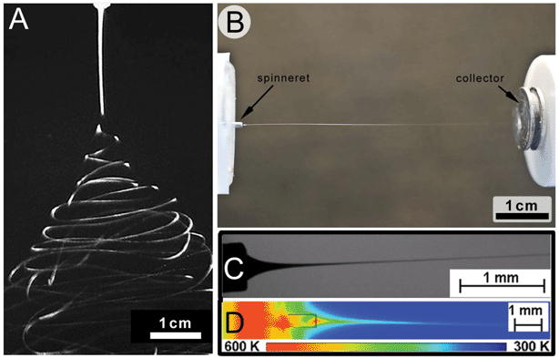 | ||
| Fig. 5 Comparison of the jet stabilities between solution and melt electrospinning. The electrified jet in solution electrospinning (A) often (but not always) has instabilities that result in a broad deposition area. In comparison, the molten electrified jet (shown in B) is often straight and visible to the eye right up to the collector. The molten jet also cools rapidly (C and D). Figure (A) is reproduced from ref. 60 and (B) is from ref. 26, while (C) and (D) are reproduced from ref. 59 with permission. | ||
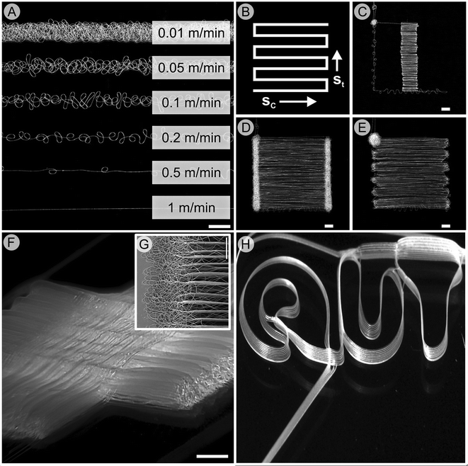 | ||
| Fig. 6 (A) Effect of stage movement speed on the shape of melt electrospun scaffolds. The collector speed (A) defines the straightness of the fiber, while the turning speed (B)–(E) is also important to ensure the fiber is not drawn prematurely (C) or forms coiled fibers at the turning point (D). A photograph of an interwoven melt electrospun scaffold with significant height (approx. 1 mm) formed in a direct writing mode is shown (F). The edge of the scaffold shown in (F) is shown in inset (G) and makes use of optimum turning speeds to minimize unwanted fiber deposition. A photograph of our university logo, written by stacking 20 μm fibers upon each other ten times can be accurately reproduced (H). Fig. (A)–(G) are from ref. 53 while (H) is from ref. 61, both reproduced with permission. | ||
By definition, AM requires a layer-by-layer construction where successive layers are bonded to create a whole structure. The opposite is commonly seen in solution electrospinning, where both shielding and charge repellency occurs, causing the deposited fibers to repel the next layer. The latter effect is particularly detrimental, and since solution electrospinning often uses a charged solvent the freshly deposited fibers usually retain some surface charge. Melt electrospinning polymers can result in minimal residual charges that lead to accurate stacking. Fig. 6H shows a photograph of our institutional and academic logo, where a fiber is accurately deposited upon another fiber ten times. Using a glass microscope as the collector, the 20 μm diameter fibers stack almost perfectly upon each other. Impressively, a total of 10 logos were written in total and were almost identical, demonstrating the reproducibility of melt electrospinning as an AM approach.
Since we are able to accurately stack new fibers upon deposited fibers in a direct writing mode, TE scaffolds from such an approach were fabricated (Fig. 7). Using a common AM approach of woodpiling,1,54,55 fibers were placed onto a collector at 90° and 120° orientations. One major difference between these scaffolds and FDM scaffolds is that the diameters of the fiber struts are over an order of magnitude smaller. Furthermore, the inter-fiber spacing relative to the fiber diameter is much higher in melt electrospinning writing. Since there is a significant gap (2–3 cm) between the spinneret and the collector, the viscous molten jet can partially cool before deposition. This means that a small filament can span across a larger air gap, effectively increasing the total porosity of the scaffold compared to FDM scaffolds.
 | ||
| Fig. 7 Melt electrospun scaffolds formed in direct writing mode using (A) 120 degree turns (B, magnified) and (C) 90 degree turns. Reproduced from ref. 53 with permission. | ||
This high porosity is demonstrated in another recent paper,56 where 180 ± 40 μm thick cell-invasive PCL scaffolds were manufactured through melt electrospinning writing for skin TE applications (Fig. 8). Micro-computed tomography (μCT) represented the electrospun written scaffolds in 3D, and applying a bone morphogenic analysis algorithm to the collected data showed a porosity of approximately 87%. This compares to the current limit of approximately 75% for FDM scaffolds.10,57 The fiber diameters of these particular melt electrospun PCL scaffolds were 7.5 ± 1.6 μm, and inter-fiber distances ranged from 8 μm to 133 μm with an average of 46 ± 22 μm, and were fully infiltrated by human dermal fibroblasts in vitro. A top-seeding method with fibroblasts was adequate to achieve this, with cells present throughout and underneath the scaffold. This was confirmed through SEM and histology. Following 7 days in vitro a cross section of the cell-scaffold construct (Fig. 8D) clearly showed evidence of ECM throughout the scaffold, as well as cellular anchorage to the scaffold fibers. Additionally, full cellular penetration, as indicated by the presence of fibroblast nuclei throughout the scaffold, occurred after 14 days in vitro (Fig. 8E and F). The orderly placement of fibers, in conjunction with low micron-diameter fibers, resulted in a 3D fibroblast-scaffold construct suitable for TE applications.
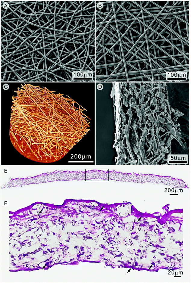 | ||
| Fig. 8 Scanning electron microscopy of PCL scaffolds produced via (A) static conditions and (B) direct writing mode. Three dimensional visualization of a melt electrospun written scaffold using μCT is shown in (C). Fibroblast infiltration of the electrospun written scaffold after 14 days was assessed via SEM (D). Histological sections of a fibroblast seeded scaffold (E) show cells present within the scaffold, in (F). The white arrows in (F) indicate PCL fibers while the black arrows show fibroblast nuclei. Figures are reproduced from ref. 56 with permission. | ||
Melt electrospinning writing onto cylindrical collectors
AM through melt electrospinning writing was also recently demonstrated with a cylindrical collector.58 The rotation of the collector was controlled, as was lateral motion along the x-axis. The combination of these two parameters allowed the fiber deposition angle to be controlled, which was shown to be a key determinant of scaffold pore morphology (e.g. size, shape, number and porosity). Melt electrospun PCL tubes with pitches of 30, 45 and 60° (Fig. 9d–f) were flexible and mechanically tested in tension and compression. A finite element model predicted the mechanical testing results, showing that a lower deposition angle provides an improved mechanical response to uniaxial tension and compression. It is important to note here that the rotation of the cylinder is not to pull the fiber onto the collector but to control the deposition. If the electric field in this configuration is interrupted, the fiber collection would stop.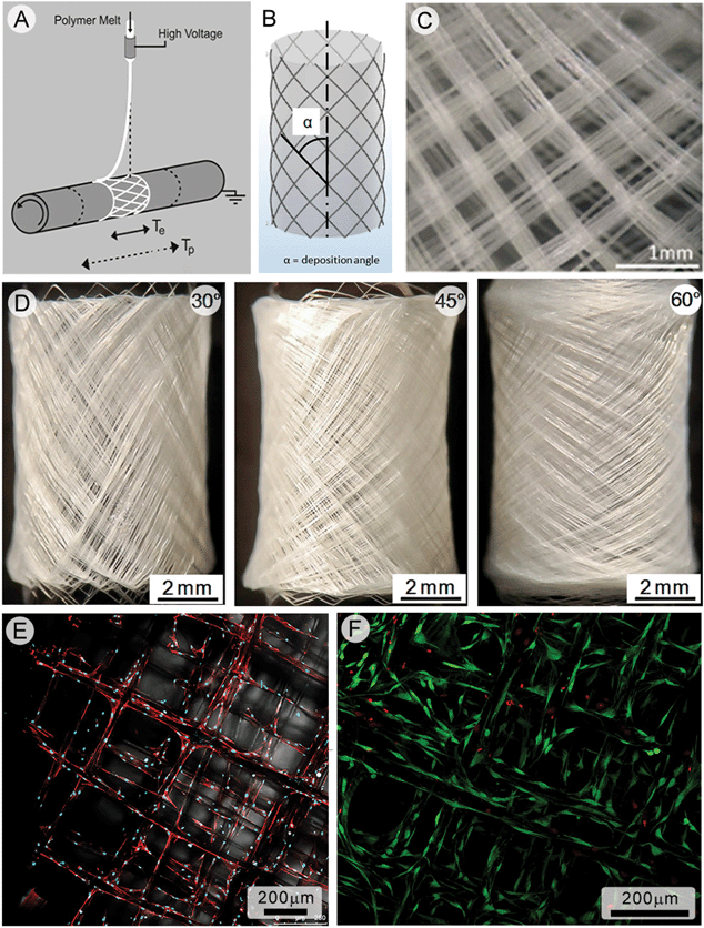 | ||
| Fig. 9 Melt electrospinning writing onto a cylindrical collector to produce cell invasive tubular structures. Schematics of fiber deposition onto the cylindrical collector are shown (a, b) as well as a microscope image of the deposited fibers (c). Photographs (d)–(f) are of tubular scaffolds made using a deposition pitch of 30°, 45° and 60°. Human osteoblasts are seeded onto the scaffold and actin fibers imaged with confocal laser scanning microscopy (e), while live-dead imaging (f) shows that over 90% of osteoblasts are alive after 2 weeks in vitro. Figures reproduced from ref. 8. | ||
Unlike many other solution electrospun tubes, the melt electrospun PCL tube can truly be considered a scaffold, supporting the ingrowth of three different cell types in vitro. Using μCT measurements, a porosity of 86–87% and a pore area of 0.05 mm2 was calculated for the scaffolds. Prior to cell seeding, the PCL fibers were coated in CaP to enhance osteoinduction. Cell vitality and proliferation remained high for primary human osteoblasts as well as mouse osteoblasts, demonstrating good biocompatibility.
Comparing melt electrospinning writing with FDM
The widely accepted AM approach that is most similar to melt electrospinning writing is FDM. The configuration of melt electrospinning writing devices has some important distinctions to FDM systems (Fig. 10). Firstly, the diameter of the filament in melt electrospinning is reduced when the electrified jet passes through the air—not through the nozzle as in FDM. Therefore the spinneret diameter can be much larger, with the resulting filaments much smaller than FDM. Therefore, the pressure at the spinneret tip for melt electrospinning is much lower than FDM. Furthermore, the nozzle-to-collector distance is much lower for FDM, and a z-stage controlling the height of deposition is required. With melt electrospinning, the spinneret–collector distance is much larger, and a z-stage is not required to build up layers. A consequence is that rapid cooling of the melt electrospun fiber occurs (Fig. 5C and D).59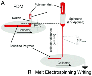 | ||
| Fig. 10 Schematic highlighting some distinctions between FDM and melt electrospinning writing. For FDM (A), the polymer melt must be pushed through a fine nozzle to attain small diameter filaments, creating significant pressures due to melt flow. Melt electrospinning (B) can have a much larger diameter spinneret, since the diameter reduction of the filament takes place across a large air gap due to surface charges on the electrified jet. Due to this large air gap, melt electrospinning writing does not need stage movement in the z-direction. Ultimately the filaments are smaller—currently down to 5 μm, compared to a 100 μm limit for FDM systems. | ||
Applying AM principles to melt electrospinning for biomedical science is in its infancy, however initial outcomes suggest the approach is very promising. Firstly, the fiber placement is well controlled, and the filament diameters are usually in the low micron region. Pores are interconnected and sufficiently large (20 μm and above) to support cell and tissue growth throughout the scaffold architecture. As shown in this review, medical grade polymers such as PCL can be processed without adverse biological effects. It is important though, that cytotoxicity testing and investigation of the degradation properties of polymer melts is performed such that the different scaffold designs are studied for specific TE applications. Long-term preclinical animal studies, followed by in depth analysis of different orders of magnitude from macro- to micro- to nano-scale, using sophisticated methods to prove the outcome of highly organized and functional regenerated tissue, is crucial to the future development and optimization of melt electrospun scaffolds. Additionally, processes previously developed to surface modify polymers can be used with this process. As an example, CaP was deposited on melt electrospun fibers, resulting in improved osteoblast adhesion and mineralization. Finally, the rapid cooling of the polymer melt allows experiments where fibers are written directly upon cells or tissues. While this expands the capacity to assemble diverse TE constructs, there are still many biological experiments to determine the effects of fiber deposition (and electrostatics) upon cell viability and behavior.
Future outlook
There is a growing need to develop new scaffold manufacturing techniques, as TE approaches become more complex and functional. A recent interest in bimodal and multiphasic scaffolds for TE requires improved control over how such structures are made. Electrospinning as an AM approach can fill this need to produce 3D scaffolds with systematic variations in morphology. While melt electrospinning is not considered useful for nanofiber production, there are compelling arguments for its use in TE scaffold production. With only four recent papers published on this technique, melt electrospinning writing is truly in its infancy. Currently, the process is reported in only one TE laboratory worldwide and has been shown to be a reproducible, robust and flexible process in manufacturing biomedical materials. We anticipate that a review on how electrospinning and AM can be beneficially combined will spark interest in the biomaterials community. This TE scaffold manufacturing approach is potentially very powerful as the number of polymers used will certainly expand, and the structures designed and fabricated become more complex.References
- D. W. Hutmacher, T. Woodfield, P. D. Dalton and J. Lewis, Scaffold design and fabrication, in Tissue Engineering, ed. C. Van Blitterswijk, P. Thompsen, A. Lindhal, J. Hubbell, D. F. Williams, R. Canceddaet al., Academic Press, 2008, pp. 403–450 Search PubMed.
- D. D. Kim, M. M. Takeno, B. D. Ratner and T. A. Horbett, Glow discharge plasma deposition (GDPD) technique for the local controlled delivery of hirudin from biomaterials, Pharm. Res., 1998, 15, 783–786 CrossRef CAS.
- C. E. Holy, S. M. Dang, J. E. Davies and M. S. Shoichet, In vitro degradation of a novel poly(lactide-co-glycolide) 75/25 foam, Biomaterials, 1999, 20, 1177–1185 CrossRef CAS.
- T. V. Chirila, B. Higgins and P. D. Dalton, The effect of synthesis conditions on the properties of poly(2-hydroxyethyl methacrylate) sponges, Cell Polym., 1998, 17, 141–162 CAS.
- P. D. Dalton, T. Woodfield and D. W. Hutmacher, Snap shot: polymer scaffolds for tissue engineering (vol. 30, p. 701, 2009), Biomaterials, 2009, 30, 2420 CrossRef CAS.
- C. E. Holy, C. Cheng, J. E. Davies and M. S. Shoichet, Optimizing the sterilization of PLGA scaffolds for use in tissue engineering, Biomaterials, 2001, 22, 25–31 CrossRef CAS.
- N. Bhardwaj and S. C. Kundu, Electrospinning: a fascinating fiber fabrication technique, Biotechnol. Adv., 2010, 28, 325–347 CrossRef CAS.
- D. W. Hutmacher, Scaffold-based tissue engineering – design and fabrication of matrices using solid freeform fabrication techniques. Advanced manufacturing technology for medical applications: reverse engineering, software conversion and rapid prototyping, 2005, pp. 163–189.
- D. W. Hutmacher, M. Sittinger and M. V. Risbud, Scaffold-based tissue engineering: rationale for computer-aided design and solid free-form fabrication systems, Trends Biotechnol., 2004, 22, 354–362 CrossRef CAS.
- D. W. Hutmacher, T. Schantz, I. Zein, K. W. Ng, S. H. Teoh and K. C. Tan, Mechanical properties and cell cultural response of polycaprolactone scaffolds designed and fabricated via fused deposition modeling, J. Biomed. Mater. Res., 2001, 55, 203–216 CrossRef CAS.
- C. K. Chua, K. F. Leong, N. Sudarmadji, M. J. J. Liu and S. M. Chou, Selective laser sintering of functionally graded tissue scaffolds, MRS Bull., 2011, 36, 1006–1014 CrossRef CAS.
- T. Niino, D. Hamajima, K. Montagne, S. Oizumi, H. Naruke and H. Huang, et al., Laser sintering fabrication of three-dimensional tissue engineering scaffolds with a flow channel network, Biofabrication, 2011, 3, 034107 CrossRef.
- F. P. W. Melchels, J. Feijen and D. W. Grijpma, A review on stereolithography and its applications in biomedical engineering, Biomaterials, 2010, 31, 6121–6130 CrossRef CAS.
- B. Guillotin and F. Guillemot, Cell patterning technologies for organotypic tissue fabrication, Trends Biotechnol., 2011, 29, 183–190 CrossRef CAS.
- S. Desai and B. Harrison, Direct-writing of biomedia for drug delivery and tissue regeneration, in Printed Biomaterials: Novel Processing and Modeling Techniques for Medicine and Surgery, ed. R. Narayan, T. Boland and Y. S. Lee, Springer, New York, 2010, pp. 71–89 Search PubMed.
- J. H. Jang, O. Castano and H. W. Kim, Electrospun materials as potential platforms for bone tissue engineering, Adv. Drug Delivery Rev., 2009, 61, 1065–1083 CrossRef CAS.
- Q. P. Pham, U. Sharma and A. G. Mikos, Electrospinning of polymeric nanofibers for tissue engineering applications: a review, Tissue Eng., 2006, 12, 1197–1211 CrossRef CAS.
- C. Vaquette and J. J. Cooper-White, Increasing electrospun scaffold pore size with tailored collectors for improved cell penetration, Acta Biomater., 2011, 7, 2544–2557 CrossRef CAS.
- D. M. Zhang and J. Chang, Patterning of electrospun fibers using electroconductive templates, Adv. Mater., 2007, 19, 3664–3367 CrossRef CAS.
- K. Sombatmankhong, O. Suwantong, S. Waleetorncheepsawat and P. Supaphol, Electrospun fiber mats of poly(3-hydroxybutyrate), poly(3-hydroxybutyrate-co-3-hydroxyvalerate), and their blends, J. Polym. Sci., Part B: Polym. Phys., 2006, 44, 2923–2933 CrossRef CAS.
- H. W. Tong, M. Wang and W. W. Lu, Electrospun poly(hydroxybutyrate-co-hydroxyvalerate) fibrous membranes consisting of parallel-aligned fibers or cross-aligned fibers: characterization and biological evaluation, J. Biomater. Sci., Polym. Ed., 2011, 22, 2475–2497 CrossRef CAS.
- D. W. Hutmacher and P. D. Dalton, Melt electrospinning, Chem.–Asian J., 2011, 6, 44–56 CrossRef CAS.
- L. Rayleigh, On the equilibrium of liquid conducting masses charged with electricity, Philos. Mag., Ser. 5, 1882, 5, 184–186 CrossRef.
- S. V. Fridrikh, J. H. Yu, M. P. Brenner and G. C. Rutledge, Controlling the fiber diameter during electrospinning, Phys. Rev. Lett., 2003, 90 Search PubMed.
- D. H. Reneker and A. L. Yarin, Electrospinning jets and polymer nanofibers, Polymer, 2008, 49, 2387–2425 CrossRef CAS.
- P. D. Dalton, D. Grafahrend, K. Klinkhammer, D. Klee and M. Moller, Electrospinning of polymer melts: phenomenological observations, Polymer, 2007, 48, 6823–6833 CrossRef CAS.
- H. J. Zhou, T. B. Green and Y. L. Joo, The thermal effects on electrospinning of polylactic acid melts, Polymer, 2006, 47, 7497–7505 CrossRef CAS.
- D. M. Zhang and J. Chang, Electrospinning of three-dimensional nanofibrous tubes with controllable architectures, Nano Lett., 2008, 8, 3283–3287 CrossRef CAS.
- A. Subramanian, D. Vu, G. F. Larsen and H. Y. Lin, Preparation and evaluation of the electrospun chitosan/PEO fibers for potential applications in cartilage tissue engineering, J. Biomater. Sci., Polym. Ed., 2005, 16, 861–873 CrossRef CAS.
- E. Smit, U. Buttner and R. D. Sanderson, Continuous yarns from electrospun fibers, Polymer, 2005, 46, 2419–2423 CrossRef CAS.
- J. M. Deitzel, J. D. Kleinmeyer, J. K. Hirvonen and N. C. B. Tan, Controlled deposition of electrospun poly(ethylene oxide) fibers, Polymer, 2001, 42, 8163–8170 CrossRef CAS.
- P. D. Dalton, D. Klee and M. Moller, Electrospinning with dual collection rings, Polymer, 2005, 46, 611–614 CrossRef CAS.
- J. Gerardo-Nava, T. Fuhrmann, K. Klinkhammer, N. Seiler, J. Mey and D. Klee, et al., Human neural cell interactions with orientated electrospun nanofibers in vitro, Nanomedicine, 2009, 4, 11–30 CrossRef CAS.
- C. Vaquette and J. Cooper-White, The use of an electrostatic lens to enhance the efficiency of the electrospinning process, Cell Tissue Res., 2012, 347, 815–826 CrossRef CAS.
- N. M. Neves, R. Campos, A. Pedro, J. Cunha, F. Macedo and R. L. Reis, Patterning of polymer nanofiber meshes by electrospinning for biomedical applications, Int. J. Nanomed., 2007, 2, 433–448 CAS.
- Y. Wang, G. Wang, L. Chen, H. Li, T. Yin and B. Wang, et al., Electrospun nanofiber meshes with tailored architectures and patterns as potential tissue-engineering scaffolds, Biofabrication, 2009, 1, 015001 CrossRef.
- S. H. Park, T. G. Kim, H. C. Kim, D. Y. Yang and T. G. Park, Development of dual scale scaffolds via direct polymer melt deposition and electrospinning for applications in tissue regeneration, Acta Biomater., 2008, 4, 1198–1207 CrossRef CAS.
- G. Kim, J. Son, S. Park and W. Kim, Hybrid process for fabricating 3D hierarchical scaffolds combining rapid prototyping and electrospinning, Macromol. Rapid Commun., 2008, 29, 1577–1581 CrossRef CAS.
- L. Moroni, J. R. De Wijn and C. A. Van Blitterswijk, Integrating novel technologies to fabricate smart scaffolds, J. Biomater. Sci., Polym. Ed., 2008, 19, 543–572 CrossRef CAS.
- M. Centola, A. Rainer, C. Spadaccio, S. De Porcellinis, J. A. Genovese and M. Trombetta, Combining electrospinning and fused deposition modeling for the fabrication of a hybrid vascular graft, Biofabrication, 2010, 2, 014102 CrossRef CAS.
- R. Gentsch, B. Boysen, A. Lankenau and H. G. Borner, Single-step electrospinning of bimodal fiber meshes for ease of cellular infiltration, Macromol. Rapid Commun., 2010, 31, 59–64 CrossRef CAS.
- S. J. Kim, D. H. Jang, W. H. Park and B. M. Min, Fabrication and characterization of 3-dimensional PLGA nanofiber/microfiber composite scaffolds, Polymer, 2010, 51, 1320–1327 CrossRef CAS.
- S. W. Chung, N. P. Ingle, G. A. Montero, S. H. Kim and M. W. King, Bioresorbable elastomeric vascular tissue engineering scaffolds via melt spinning and electrospinning, Acta Biomater., 2010, 6, 1958–1967 CrossRef CAS.
- S. Soliman, S. Pagliari, A. Rinaldi, G. Forte, R. Fiaccavento and F. Pagliari, et al., Multiscale three-dimensional scaffolds for soft tissue engineering via multimodal electrospinning, Acta Biomater., 2010, 6, 1227–1237 CrossRef CAS.
- C. Vaquette, W. Fan, Y. Xiao, S. Hamlet, D. W. Hutmacher and S. Ivanovski, A biphasic scaffold design combined with cell sheet technology for simultaneous regeneration of alveolar bone/periodontal ligament complex, Biomaterials, 2012, 33, 5560–5573 CrossRef CAS.
- J. Kameoka, R. Orth, Y. N. Yang, D. Czaplewski, R. Mathers and G. W. Coates, et al., A scanning tip electrospinning source for deposition of oriented nanofibres, Nanotechnology, 2003, 14, 1124–1129 CrossRef CAS.
- D. H. Sun, C. Chang, S. Li and L. W. Lin, Near-field electrospinning, Nano Lett., 2006, 6, 839–842 CrossRef CAS.
- C. Hellmann, J. Belardi, R. Dersch, A. Greiner, J. H. Wendorff and S. Bahnmueller, High precision deposition electrospinning of nanofibers and nanofiber nonwovens, Polymer, 2009, 50, 1197–1205 CrossRef CAS.
- C. Chang, K. Limkrailassiri and L. W. Lin, Continuous near-field electrospinning for large area deposition of orderly nanofiber patterns, Appl. Phys. Lett., 2008, 93 Search PubMed.
- S. H. Ahn, H. J. Lee and G. H. Kim, Polycaprolactone scaffolds fabricated with an advanced electrohydrodynamic direct-printing method for bone tissue regeneration, Biomacromolecules, 2011, 12, 4256–4263 CrossRef CAS.
- J. Lee, S. Y. Lee, J. Jang, Y. H. Jeong and D. W. Cho, Fabrication of patterned nanofibrous; mats using direct-write electrospinning, Langmuir, 2012, 28, 7267–7275 CrossRef CAS.
- P. D. Dalton, K. Klinkhammer, J. Salber, D. Klee and M. Moller, Direct in vitro electrospinning with polymer melts, Biomacromolecules, 2006, 7, 686–690 CrossRef CAS.
- T. D. Brown, P. D. Dalton and D. W. Hutmacher, Direct writing by way of melt electrospinning, Adv. Mater., 2011, 23, 5651–5657 CrossRef CAS.
- J. A. Lewis, Direct ink writing of 3D functional materials, Adv. Funct. Mater., 2006, 16, 2193–2204 CrossRef CAS.
- D. Therriault, S. R. White and J. A. Lewis, Chaotic mixing in three-dimensional microvascular networks fabricated by direct-write assembly, Nat. Mater., 2003, 2, 265–271 CrossRef CAS.
- B. L. Farrugia, T. D. Brown, P. D. Dalton, Z. Upton and T. R. Dargaville, Enhanced cellular infiltration of dermal fibroblasts into poly(ε-caprolactone) scaffolds formed by melt Electrospinning writing, Biofabrication Search PubMed , submitted.
- J. T. Schantz, M. M. L. Ng, P. Netto, J. C. L. Ming, K. M. Wong and D. W. Hutmacher, et al., Application of an X-ray microscopy technique to evaluate tissue-engineered bone-scaffold constructs, Mater. Sci. Eng., C, 2002, 20, 9–17 CrossRef.
- T. D. Brown, A. Slotosch, L. Thibaudeau, A. Taubenberger, D. Loessner and C. Vaquette, et al., Design and fabrication of tubular scaffolds via direct writing in a melt electrospinning mode, Biointerphases, 2012, 7, 13 CrossRef CAS.
- E. Zhmayev, D. Cho and Y. L. Joo, Electrohydrodynamic quenching in polymer melt electrospinning, Phys. Fluids, 2011, 23, 073102 CrossRef.
- T. Han, D. H. Reneker and A. L. Yarin, Buckling of jets in electrospinning, Polymer, 2007, 48, 6064–6076 CrossRef CAS.
- T. D. Brown, C. Vaquette, D. W. Hutmacher and P. D. Dalton, Electrospinning for Regenerative Medicine. Polymeric Biomaterials: Structure and Function, vol. 1, ch. 16, in press Search PubMed.
| This journal is © The Royal Society of Chemistry 2013 |
