Magadiite templated high surface area graphene-type carbons from metal-halide based ionic liquids†
Pasquale Fernando
Fulvio
*a,
Patrick Christopher
Hillesheim
a,
John Christopher
Bauer
a,
Shannon Mark
Mahurin
a and
Sheng
Dai
*ab
aChemical Sciences Division, Oak Ridge National Laboratory, Oak Ridge, Tennessee 37831, USA. E-mail: fulviopf@ornl.gov
bDepartment of Chemistry, University of Tennessee, Knoxville, Tennessee 37996, USA. E-mail: dais@ornl.gov; Fax: +1-865-576-5235; Tel: +1-865-576-7307
First published on 5th November 2012
Abstract
Dispersible graphene-type carbon powders were prepared with metal halide-ionic liquids as the carbon source and Magadiite, a layered sodium silicate, as the template. The metal halide has a major impact on the graphene yield, ordering of the carbon lattice, and adsorption properties.
Among the various types of carbons with interesting electronic, thermal, and mechanical properties is graphene.1–4 Graphene is a 2-dimensional material with a hexagonal carbon lattice and delocalized π electrons. Graphene has been prepared by micromechanical exfoliation of highly oriented pyrolitic graphite (HOPG),1 among various chemical methods for its large scale production.5–7 Also technologically relevant are colloidal suspensions of this material, which allow for the fabrication of free-standing membranes.8–10 To date, methods for preparing suspensions of few layer graphene include the chemical exfoliation of natural graphite or graphite oxide in various solvents11–15 and ionic liquids.16 Ionic liquids (ILs) are typically defined as a combination of an organic cation and an inorganic anion which melt below 100 °C.17,18 Compared to organic solvents, ILs offer several advantages, including low vapour pressure and high thermal stability.19 Recently, it has been shown that IL molecules stabilize the surface of graphene, even when combined with other solvents.16
In addition to being excellent solvents for the exfoliation of graphite, ILs have been used as carbon precursors. ILs with cross-linkable functional groups can be easily converted into functional carbon materials with slit-like mesopores via thermal polymerization and carbonization without a hard-template.20,21 In the absence of cross-linkable groups, i.e. n-alkyl imidazolium ionic liquids, hard-templates are required to induce a carbon yield from the IL precursor.22–24 To further facilitate the formation of carbon material, transition metals can be introduced into the precursors. The fluidity of these IL precursors not only facilitates handling and eliminates the need for other solvents, but allows for the selection of metal cations known to catalyse the graphitization of carbonaceous materials during low temperature thermal treatments.25 If combined with a suitable template, high surface area graphene could be obtained.
Carbons exhibiting slit-like mesopores have been recently prepared from sucrose,26 furfuryl alcohol,27,28 pyrene, styrene, various olefins, acrylonitrile, and vinyl-containing28,29 precursors using layered silicates and clays as templates. These carbons were successfully employed as lithium ion battery anodes.27,29 However, bulky layered carbon particles with only few graphene edges were obtained,26 hence, the need to find precursors suitable for making graphene-type materials in higher yield using layered silicates as templates.
In this work, high surface area carbon nanosheets were prepared from transition metal halide-ILs (manganese, nickel, iron, and cobalt) using a layered silicate, namely Magadiite, as a template. Bmim[Br], a solid at room temperature, can form a eutectic liquid when mixed with certain metal salts. Briefly, Magadiite (MAG) was first impregnated in large excess of either the MnCl2-, NiCl2-, FeCl3-, or CoCl2-containing Bmim[Br] eutectic liquid (1/2.5 wt ratio MAG to IL). The mixture was then placed in an ultrasonic bath for 12 hours. The composite material was then carbonized at 900 °C, and the silicates were etched with 4 M aqueous ammonium bifluoride (NH4F·HF). In order to examine the effects of the transition metal on the formed carbons, a metal-free ethanol solution of Bmim[Br] was also used as a carbon source.
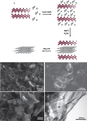
The proposed general mechanism, shown in Fig. 1A, involves the intercalation of the metal halide-IL within the Magadiite layers. Intercalation proceeds until exfoliation of the silicate into few layer organic–inorganic nanocomposites. During the carbonization, the confined metal-IL is converted into carbons with similar morphology found for exfoliated multilayer graphene materials, with some additional bulk porous particles. Ionic liquids without cross-linkable moieties display very low or negligible carbon yield due to the lack of stable polymeric intermediates or formation of volatile decomposition intermediates. Confinement in inorganic matrices, however, induces the formation of char within nanopores22 or between silicate nanosheets as in the present work. The starting Magadiite template contained some cristobalite silica as an impurity, as shown by its powder XRD pattern (Fig. S1A in the ESI†). Crystalline SiO2 was also identified in the powder XRD patterns for all other silica–carbon nanocomposites. The presence of this particular silica phase may explain the formation of the bulk carbon particles formed in addition to graphenes.
 | ||
| Fig. 1 General mechanism for the Magadiite-templated synthesis of graphene-type nanosheets showing the exfoliation of Magadiite by the metal halide-ionic liquids, carbonization of the confined metal halide-ILs, and final nanosheets after metal silicate dissolution (A). SEM images of C/Fe-IL (B) and C/Ni-IL (C) materials. Micrometer-size particles with platelet morphology formed by the stacking of graphene layers are seen. STEM images of dispersed graphene-type carbon C/Mn-IL under SE (D) mode and TE mode (E), respectively. Residual nanoparticles characterized by powder XRD as NH4MnF3 formed during the Magadiite template etching. | ||
Scanning electron microscopy (SEM) images for selected silicate-free carbons are shown in Fig. 1 and Fig. S2 in the ESI.† These carbons exhibit micron-size large platelet particles formed by stacking of the graphene-type nanosheets, as shown for C/Fe-IL and C/Ni-IL in Fig. 1B and C, respectively. Micron-size graphene sheets are seen on the SEM images of dispersed C/Mn-IL (Fig. 1D). Small nanoparticles are also visible on the surfaces of these sheets in the HRTEM image (Fig. 1E). Nanoparticles were also observed for the other materials, and their contents were less than 35 wt% according to TG analysis (Fig. S3 in the ESI†) after the oxidation of the carbon parts. These nanoparticles were identified by powder XRD (Fig. S1B in the ESI†) as Co(OH)2 for C/Co-IL, or (NH4)3FeF6 and (NH4)MnF3 for C/Fe-IL and C/Mn-IL, respectively. These residual particles were formed during the Magadiite dissolution step using NH4F·HF.
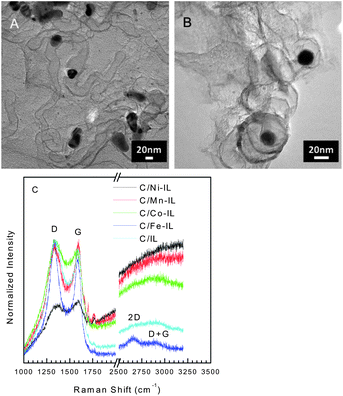
In addition to nanoparticles, graphitic structures are observed, as seen in the HRTEM images for C/Co-IL and C/Ni-IL (see Fig. 2A and B). Such graphitized domains coincide with the locations of the metal nanoparticles that are formed during thermal treatments, with graphitization of the carbon. The presence of some graphitic carbon is also supported by powder XRD and oxidation steps above 500 °C in the TG of C/Fe-IL, C/Ni-IL, and C/Co-IL. The Raman spectra collected after dissolution of the silica template are typical of most disordered carbons, see Fig. 2C. Most samples exhibit narrow G bands, indicating partial ordering of the graphene lattice. The C/Fe-IL sample further exhibits two additional bands assigned to the 2D and D + G modes found for graphitic structures, thus pointing to the effect of the metal salt used in the starting ILs. Nonetheless, it should be stressed that the structure of the graphene sheets produced is essentially disordered, with large population of defect sites found in turbostratic carbons.
 | ||
| Fig. 2 Representative HRTEM images of C/Co-IL (A) and C/Ni-IL (B) displaying graphitic domains formed during reduction of metal particles. Scale bars show 20 nm. Raman spectra (λ = 632.8 nm) for carbons prepared from the various ILs with characteristic D and G bands for disordered carbons. Narrow G bands in addition to 2D and D + G modes indicate higher ordering in the carbon lattice found for other graphitic nanomaterials. | ||
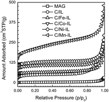
Type II adsorption isotherms with H2 hysteresis loops (Fig. 3) for N2 at −196 °C agree with the layered structure having large textural pores formed between particles shown in the SEM images. In general, the total pore volume and specific surface areas for the final carbons were considerably higher than those found for the starting Magadiite template. These parameters increased from the C/IL sample to those containing metals, in the order Fe, Co, Ni and Mn, as summarized in Table 1. Also, the adsorption isotherm for the C/Mn-IL material reveals a small condensation step at a lower relative pressure, pointing to a broad distribution of smaller constricted mesopores formed between individual nanosheets and between the bulk carbonaceous particles formed as a by-product. In addition to textural mesopores, small amounts of micropores are found, with the highest volume found for C/Co-IL, 0.045 cm3 g−1. Such small amounts of micropores may be inherent of the nanosheets, or come from smaller disordered carbon particle aggregates. These results show that by switching the metal in these ILs, the graphene yield can be increased compared to microporous carbon particles.
 | ||
| Fig. 3 N2 77 K adsorption isotherms for Magadiite and for the graphene-type carbons after etching the silicate template. Isotherms are vertically offset in increments of 25 cm3 STP g−1 for clarity. | ||
| Sample | V SP [cm3 g−1] | S BET [m2 g−1] | V mi t [cm3 g−1] | S mi t [m2 g−1] | S ext t [m2 g−1] |
|---|---|---|---|---|---|
| a Single point pore volume from adsorption isotherms at p/p0 ∼ 0.92. b Specific surface area calculated using the BET equation in the relative pressure range of 0.05 to 0.20. c Micropore volume calculated in the t-plot range of 0.5 to 0.6 nm film thickness using the Carbon Black STSA equation (*Harkins–Jura thickness equation within 0.5–0.7 nm). d Micropore surface area calculated in the t-plot range of 0.5 to 0.6 nm film thickness using the Carbon Black STSA equation (*Harkins–Jura thickness equation within 0.5–0.7 nm). e External surface area calculated using the t-plot method. | |||||
| MAG | 0.015 | 10 | 0.001* | 3* | 7* |
| C/IL | 0.163 | 90 | 0.033 | 77 | 13 |
| C/Fe-IL | 0.072 | 49 | 0.007 | 17 | 32 |
| C/Co-IL | 0.095 | 115 | 0.045 | 98 | 17 |
| C/Ni-IL | 0.094 | 100 | 0.030 | 67 | 33 |
| C/Mn-IL | 0.388 | 413 | 0.014 | 34 | 379 |
In summary, Magadiite templated graphene-type nanosheets with slit-like mesopores and large surface areas were obtained in high yields from imidazolium IL-transition metal salts as carbon precursors. This facile method may further allow for the large scale synthesis of dispersible carbon nanosheet powders and membranes8–10 for energy storage and conversion devices.27,29
This work was supported as part of the Fluid Interface Reactions, Structures and Transport (FIRST) Center, an Energy Frontier Research Center funded by the US Department of Energy, Office of Science, Office of Basic Energy Sciences.
Notes and references
- K. S. Novoselov, A. K. Geim, S. V. Morozov, D. Jiang, Y. Zhang, S. V. Dubonos, I. V. Grigorieva and A. A. Firsov, Science, 2004, 306, 666 CrossRef CAS.
- A. K. Geim and K. S. Novoselov, Nat. Mater., 2007, 6, 183 CrossRef CAS.
- C. N. R. Rao, A. K. Sood, K. S. Subrahmanyam and A. Govindaraj, Angew. Chem., Int. Ed., 2009, 48, 7752 CrossRef CAS.
- D. E. Jiang, B. G. Sumpter and S. Dai, J. Chem. Phys., 2007, 126, 134701 CrossRef.
- S. Park and R. S. Ruoff, Nat. Nanotechnol., 2009, 4, 217 CrossRef CAS.
- D. Li, M. B. Muller, S. Gilje, R. B. Kaner and G. G. Wallace, Nat. Nanotechnol., 2008, 3, 101 CrossRef CAS.
- V. C. Tung, M. J. Allen, Y. Yang and R. B. Kaner, Nat. Nanotechnol., 2009, 4, 25 CrossRef CAS.
- C. Chen, Q.-H. Yang, Y. Yang, W. Lv, Y. Wen, P.-X. Hou, M. Wang and H.-M. Cheng, Adv. Mater., 2009, 21, 3007 CrossRef CAS.
- D. A. Dikin, S. Stankovich, E. J. Zimney, R. D. Piner, G. H. B. Dommett, G. Evmenenko, S. T. Nguyen and R. S. Ruoff, Nature, 2007, 448, 457 CrossRef CAS.
- D. D. Kulkarni, I. Choi, S. Singamaneni and V. V. Tsukruk, ACS Nano, 2010, 4, 4667 CrossRef CAS.
- Y. Hernandez, V. Nicolosi, M. Lotya, F. M. Blighe, Z. Y. Sun, S. De, I. T. McGovern, B. Holland, M. Byrne, Y. K. Gun'ko, J. J. Boland, P. Niraj, G. Duesberg, S. Krishnamurthy, R. Goodhue, J. Hutchison, V. Scardaci, A. C. Ferrari and J. N. Coleman, Nat. Nanotechnol., 2008, 3, 563 CrossRef CAS.
- M. Lotya, Y. Hernandez, P. J. King, R. J. Smith, V. Nicolosi, L. S. Karlsson, F. M. Blighe, S. De, Z. M. Wang, I. T. McGovern, G. S. Duesberg and J. N. Coleman, J. Am. Chem. Soc., 2009, 131, 3611 CrossRef CAS.
- A. A. Green and M. C. Hersam, Nano Lett., 2009, 9, 4031 CrossRef CAS.
- V. Georgakilas, A. B. Bourlinos, R. Zboril, T. A. Steriotis, P. Dallas, A. K. Stubos and C. Trapalis, Chem. Commun., 2010, 46, 1766 RSC.
- S. Stankovich, D. A. Dikin, R. D. Piner, K. A. Kohlhaas, A. Kleinhammes, Y. Jia, Y. Wu, S. T. Nguyen and R. S. Ruoff, Carbon, 2007, 45, 1558 CrossRef CAS.
- X. Q. Wang, P. F. Fulvio, G. A. Baker, G. M. Veith, R. R. Unocic, S. M. Mahurin, M. F. Chi and S. Dai, Chem. Commun., 2010, 46, 4487 RSC.
- T. Welton, Chem. Rev., 1999, 99, 2071 CrossRef CAS.
- Z. Ma, J. H. Yu and S. Dai, Adv. Mater., 2010, 22, 261 CrossRef CAS.
- C. Chiappe and D. Pieraccini, J. Phys. Org. Chem., 2005, 18, 275 CrossRef CAS.
- J. S. Lee, X. Q. Wang, H. M. Luo and S. Dai, Adv. Mater., 2010, 22, 1004 CrossRef CAS.
- J. S. Lee, X. Q. Wang, H. M. Luo, G. A. Baker and S. Dai, J. Am. Chem. Soc., 2009, 131, 4596 CrossRef CAS.
- X. Q. Wang and S. Dai, Angew. Chem., Int. Ed., 2010, 49, 6664 CrossRef CAS.
- J. P. Paraknowitsch, A. Thomas and M. Antonietti, J. Mater. Chem., 2010, 20, 6746 RSC.
- J. P. Paraknowitsch, J. Zhang, D. S. Su, A. Thomas and M. Antonietti, Adv. Mater., 2010, 22, 87 CrossRef CAS.
- A. Oya and S. Otani, Carbon, 1979, 17, 131 CrossRef CAS.
- A. Bakandritsos, T. Steriotis and D. Petridis, Chem. Mater., 2004, 16, 1551 CrossRef CAS.
- C. J. Meyers, S. D. Shah, S. C. Patel, R. M. Sneeringer, C. A. Bessel, N. R. Dollahon, R. A. Leising and E. S. Takeuchi, J. Phys. Chem. B, 2001, 105, 2143 CrossRef CAS.
- C. Santos, M. Andrade, A. L. Vieira, A. Martins, J. Pires, C. Freire and A. P. Carvalho, Carbon, 2010, 48, 4049 CrossRef CAS.
- G. Sandi, P. Thiyagarajan, K. A. Carrado and R. E. Winans, Chem. Mater., 1999, 11, 235 CrossRef CAS.
Footnote |
| † Electronic supplementary information (ESI) available: Detailed experimental procedure, powder XRD patterns for Magadiite–carbon composites and silicate-free materials, additional SEM images for graphenes, and TG curves in air for carbons. See DOI: 10.1039/c2ta00634k |
| This journal is © The Royal Society of Chemistry 2013 |
