Positioning an individual metal–organic framework particle using a magnetic field†
Paolo
Falcaro
*a,
Florian
Lapierre
ae,
Benedetta
Marmiroli
bc,
Mark
Styles
d,
Yonggang
Zhu
ae,
Masahide
Takahashi
f,
Anita J.
Hill
ad and
Cara M.
Doherty
*a
aDivision of Materials Science and Engineering, CSIRO, Private Bag 33, Clayton South MDC 3169, Australia. E-mail: Paolo.Falcaro@csiro.au; Cara.Doherty@csiro.au; Tel: +61 3 9545 2841
bInstitute of Biophysics and Nanosystems Research, Austrian Academy of Sciences, Schmiedlstrasse 6, 8042 Graz, Austria
cSincrotrone Trieste S.C.p.A. S.S. 14, Km 163.5 Area Science Park, 34012, Basovizza, Trieste, Italy
dDivision of Process Science and Engineering, CSIRO, Private Bag 33, Clayton South MDC 3169, Australia
eMelbourne Center for Nanofabrication, 151 Wellington road, Clayton, VIC 3168, Australia
fDepartment of Materials Science, Osaka Prefecture University, Sakai, Osaka 599-8531, Japan
First published on 23rd October 2012
Abstract
For the first time an external magnetic field has been used for the spatial control of a single amino functionalized mixed component metal–organic framework doped with cobalt nanoparticles. The potential applications as an active material for miniaturized devices (e.g. microchannels and microfluidic circuits) are illustrated.
Metal–organic frameworks (MOFs) are a promising class of hybrid porous materials that have been widely tested for gas storage and separation.1 However, the unique properties of MOFs mean that they can also be employed for the preparation of sensors,2 luminescent devices,3 molecular sequestrating agents4 and storage-release materials.5 Due to their potential technological applications, MOFs are promising materials for the fabrication of advanced devices. However, to enable the use of the ultra-porous crystals within miniaturized device platforms, techniques for accurately positioning MOFs need to be developed. In this rapidly evolving area of research, different approaches for positioning MOFs are currently under investigation.6 For example, methods including surface functionalization,7,8 electrodeposition,9 heterogeneous seeding,10 micro-contact printing,11 photolithography,12 Langmuir–Blodgettry13 and pseudomorphic replication14 have shown interesting results for permanently positioning MOFs on a substrate. While the capability of positioning individual MOF crystals has been proven for some of the previously mentioned protocols, the dynamic control of a single MOF particle has not been previously reported.6 This single crystal control would allow for the full exploitation of the MOF functional properties, enabling new additional abilities within miniaturized platforms. For instance, the MOF crystal could be used as a repositionable ultra-porous material that could offer “on demand” molecular catalysis, sensing, selective absorbing, gating, storage or controlled release. The precise control of such functional properties would facilitate the fabrication of new integrated devices such as a lab-on-a-chip.
The concept of MOFs as repositionable vessels can be achieved using an external field to relocate the crystal without altering the functional features. This can be achieved using the approach proposed by Lohe et al.,5 who investigated the growth of MOFs on superparamagnetic nanoparticles (γ-Fe2O3) and used a magnetic field to collect the nanocomposite porous crystals. This study presented the potential of magnetic composite nanoporous crystals for drug delivery applications (e.g. ibuprofen). Significant advancements have been further obtained by controlling the position of higher surface area MOFs (e.g. MOF-5) using stable embedded ferromagnetic cobalt nanoparticles with a strong magnetic response.15 A magnetic field was used to confine magnetic MOF crystals to a small area, where subsequent secondary growth and the application for sensing were also proved.15 Other studies have subsequently highlighted how nano-composite based MOFs (also called framework composites, FCs10) can be used to release drugs for cancer treatment16 or to sequester potential carcinogenic molecules.4,17
Because magnetic FCs have shown the potential for controlled delivery, uptake or sensing materials, the ability to achieve their precise positioning in a miniaturized device (e.g. microfluidic platform) is an important technological target. In this communication we present a proof of concept for positioning of a magnetic FC, based on a mixed component metal–organic framework (MC–MOF18), embedding carbon coated cobalt nanoparticles (<50 nm (ref. 19)). The framework has been obtained with a mixture of dicarboxylic ligands (i.e. 1,4-benzenedicarboxylate, BDC, 75%; 2-amino-1,4-benzenedicarboxylate, NH2–BDC, 25%) connected by Zn4O clusters. While the use of 100% BDC ligand would generate MOF-5, the use of 100% NH2–BDC ligand would form IRMOF-3, the 3![[thin space (1/6-em)]](https://www.rsc.org/images/entities/char_2009.gif) :
:![[thin space (1/6-em)]](https://www.rsc.org/images/entities/char_2009.gif) 1 mixture used here generates a cubic (Fm
1 mixture used here generates a cubic (Fm![[3 with combining tilde]](https://www.rsc.org/images/entities/char_0033_0303.gif) m) framework similar to MOF-5 with randomly distributed amino-functionalized ligands (see Fig. S1.1 in ESI†). Although the synthesis of such MC–MOFs has already been reported,20 this concept has not previously been applied for the preparation of FCs. In this paper the amino functionalized mixed component MOF embedding magnetic nanoparticles is named NH2–MC–FC. With respect to the previously reported embedding of carbon coated cobalt nanoparticles in MOF-5,15 here we present several novel concepts including: (1) the use of mixed ligands for a FC preparation, (2) a significant reduction in the quantity of magnetic nanoparticles required (details are provided in the ESI†), (3) the improvement of position control (the NH2–MC–FC can be used in microfluidic circuits) and (4) further insight into the crystallinity when functional nanoparticles are embedded.
m) framework similar to MOF-5 with randomly distributed amino-functionalized ligands (see Fig. S1.1 in ESI†). Although the synthesis of such MC–MOFs has already been reported,20 this concept has not previously been applied for the preparation of FCs. In this paper the amino functionalized mixed component MOF embedding magnetic nanoparticles is named NH2–MC–FC. With respect to the previously reported embedding of carbon coated cobalt nanoparticles in MOF-5,15 here we present several novel concepts including: (1) the use of mixed ligands for a FC preparation, (2) a significant reduction in the quantity of magnetic nanoparticles required (details are provided in the ESI†), (3) the improvement of position control (the NH2–MC–FC can be used in microfluidic circuits) and (4) further insight into the crystallinity when functional nanoparticles are embedded.
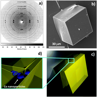
Large magnetic NH2–MC–FC cubes, with edge lengths of about 50 μm, have been obtained using the synthesis conditions described (in the ESI†). Characterisation of these cubes using single crystal X-ray diffraction techniques has revealed that they are likely to be comprised of several (approximately 3 or 4) smaller crystallites which are slightly misaligned, giving rise to multiple diffraction spots such as the doublets and triplets shown in Fig. 1a. This situation is thought to be a consequence of the embedded cobalt nanoparticles. Although many of the NH2–MC–FC particles appear to have the shape of single crystals (Fig. 1b), the nanoparticles embedded during the crystal growth can interrupt the continuity of the MC–MOF lattice and limit the size of the coherent crystalline domains as shown in the schematic presented in Fig. 1c and d.
 | ||
| Fig. 1 Single crystal X-ray diffraction measurements (a), obtained from cubic NH2–MC–FC particles (b), indicate that most of the particles contain two or more crystalline domains that are slightly misaligned (c). This situation is thought to be a consequence of the embedded Co nanoparticles (d), which interrupt the continuity of the MC–MOF lattice and limit the size of the coherent crystalline domains. | ||
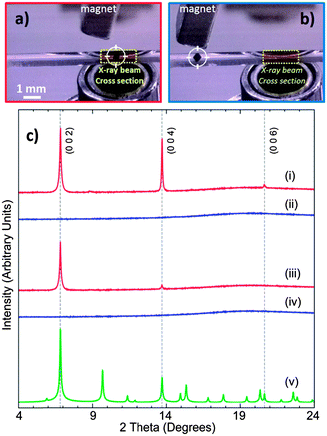
The ability to position such a FC has been demonstrated by inserting a single NH2–MC–FC cubic particle (Fig. 2a) into a glass capillary filled with ethanol. The particle was moved along the capillary using an external commercial magnet21 and alternatively positioned/removed in front of the X-ray beam of a synchrotron powder diffraction beam line (Fig. 2a and b respectively). Two of the 10 cycles of positioning/removing the same NH2–MC–FC cube are presented in Fig. 2c.
 | ||
Fig. 2 Repositioning of an amino mixed component metal–organic framework (NH2–MC–MOF) using a magnetic field; the porous crystal (dark cube marked by circular crosshairs) within a 1 mm capillary was positioned in the X-ray beam cross-section region (dotted yellow rectangle) for synchrotron powder diffraction analysis (λ = 1.5418 Å) (a); then the crystal can be repositioned in a different region (b). In this figure 2 out of 10 repositioning cycles are presented (c); the crystal was positioned in the beam area (red line, i), removed (blue line, ii), repositioned in the beam area (red line, iii) and re-removed (blue line, iv). (v) The green pattern is a simulated powder diffraction pattern of randomly oriented crystals (Fm![[3 with combining tilde]](https://www.rsc.org/images/entities/char_0033_0303.gif) m with lattice parameters a = b = c = 25.79 Å). m with lattice parameters a = b = c = 25.79 Å). | ||
The observed diffraction patterns show typically three MOF-5 peaks, [002], [004] and [006], in the 4–24° 2θ interval (Fig. 2c). Equivalent analysis of a powder sample of this material (i.e. MOF-5 powder) yields patterns with additional peaks.22,23 The lattice parameter of a cubic (Fm![[3 with combining tilde]](https://www.rsc.org/images/entities/char_0033_0303.gif) m) NH2–MC–FC particle studied in this experiment was refined using the Pawley method,24 giving a = 25.79 Å. A simulated diffraction pattern of an ideal MOF-5 powder is also provided in Fig. 2c. The width of the diffraction peaks in these patterns, which were collected from a stationary particle using a high-resolution 1-D detector, also suggests that the particle is polycrystalline, while the lack of additional peaks indicates that the crystallites are highly orientated (see Fig. 2).
m) NH2–MC–FC particle studied in this experiment was refined using the Pawley method,24 giving a = 25.79 Å. A simulated diffraction pattern of an ideal MOF-5 powder is also provided in Fig. 2c. The width of the diffraction peaks in these patterns, which were collected from a stationary particle using a high-resolution 1-D detector, also suggests that the particle is polycrystalline, while the lack of additional peaks indicates that the crystallites are highly orientated (see Fig. 2).
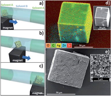
Another experiment was performed in order to prove the automated chemical uptake capability of a single crystal when combined with positioning using an external magnetic field. A methanol based solution containing either silver ions or epoxy functionalized silica nanoparticles was confined in dodecane in a 1 mm diameter glass capillary. Due to the extremely low solubility of dodecane in methanol,25 it was possible to confine the interaction of the single crystal with the silver ions or the epoxy functionalized nanoparticles within the methanol (central region). Three different regions of the solvent were formed within the glass channel (dodecane–methanol–dodecane). Each region was approximately 6 mm long with an approximate volume of 4.7 μL each. A NH2–MC–FC cubic particle was washed in methanol and then immersed in a vial with dodecane. After 5 min, the polycrystalline particle was injected into the capillary in the external region filled with the same alkane. Although easy protocols are now available to make certain types of Zn-based MOFs water stable,26 we have chosen to use the alkane due to its hydrophobicity in order to preserve the surface integrity of the NH2–MC–FC. The first experiment utilised a solution of methanol with silver ions (Ag–methanol, see ESI†). The magnetic FC was manipulated within the capillary with an external magnet and relocated from the dodecane (Fig. 3a) into 4.7 μL of Ag–methanol based solution (Fig. 3b). The FC was kept in the alcoholic solution for 5 minutes; during this time the crystal can uptake the Ag cations that have a strong affinity with the amino groups.27 Afterwards the magnet was used to relocate the FC into an adjacent apolar region (Fig. 3c). The magnetic FC was then extracted from the capillary, rinsed 5 times with methanol and then dropped on a silicon substrate for investigation by SEM and energy dispersive X-ray analysis (EDS); both the analyses are presented in Fig. 3d. From the SEM investigation, the particle presents the classical cubic shape; from the EDS overlapped signal map a strong silver emission is present as are emissions corresponding to the carbon, zinc and oxygen signals (elements constituting the MOF). The signal from silicon is emitted by the substrate and a shadow effect due to the sample titling is also observed. With this experiment we have proved that a functionalized single MOF particle can be moved within different solvents using an external magnetic driving force, and that this single particle FC vessel can uptake a metal ion from a solution in a confined volume.
 | ||
| Fig. 3 Schematic of the system used (capillary with immiscible solvents A and B). The amino functionalized mixed component single crystal embedding magnetic nanoparticles (NH2–MC–FC) has been injected in dodecane (solvent A) (a). With a magnet the NH2–MC–FC was positioned in the region filled with methanol (solvent B) (b). Then the porous crystal has been moved to the adjacent region filled with dodecane (solvent A). In experiment 1, the methanol contained Ag ions, the crystal collected the metal ions and the energy dispersive X-ray analysis showed the Ag signal (yellow colour) (d); the inset shows the SEM image. In experiment 2, the epoxy functionalized silica nanoparticles were dispersed in the methanol solution, the crystal collected the particles on its surface. The inset shows the details of the surface with the 150 nm SiO2 particles. | ||
In a similar experiment, 4.7 μL of epoxy functionalized silica nanoparticles dispersed in methanol were injected into the capillary; the colloidal solution was positioned between dodecane. The particle's magnetic responsive behaviour was used to move a fresh amino functionalized FC microparticle toward a region containing an epoxy functionalized silica nanoparticle colloidal solution in methanol (see ESI†). The NH2 groups within the crystal react with the epoxy functionalized silica nanoparticles via a well established reaction.28 The SEM image presents the particle after the washing procedure (Fig. 3e); as expected the surface of the cubic particles was decorated with SiO2 nanoparticles.
The two experiments within the capillary prove that the combination of the magnetic responsive composite and different ligands in one micrometric MOF crystal offers the chance to perform reactions at a micro-litre scale. Hence it has been shown that the MOFs can be used as a carrier for ionic species or the surface can be decorated with functionalized nanoparticles.
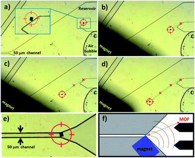
Although the previous experiments already demonstrate that the microcrystal has been moved within the miniaturized channels, we further proved the compatibility of this approach within more complex miniaturized platforms such as a microfluidic device (see ESI†). Despite the potential of incorporating MOFs into integrated platforms, the positioning of the ultra-porous crystals within the microfluidic circuit is at a very early stage of research; indeed, the only study presenting the control on positioning MOFs within a microfluidic circuit discloses how to permanently localize HKUST-1 crystals.29 In order to prove the potential of dynamic repositionable MOFs, we have introduced a 50 μm sized NH2–MC–FC into a microfluidic circuit filled with pure ethanol. The crystal has been positioned in a reservoir to allow for free motion on a surface. The nominal height of the reservoir was 55 μm. The cubic crystal has been moved by placing the magnet close to the crystal at different steps; the NH2–MC–FC moves because it is attracted by the external magnet (the pumps were turned off and an air bubble proves the static conditions of the solvent, Fig. 4a–d). The 50 μm sized NH2–MC–FC has been moved along a path of about 1 cm and positioned in front of the 50 μm wide channel (Fig. 4e) suggesting a possible use as a perm-selective gate. In addition, the ability to combine the MOFs' properties with magnetic responsive positioning within a microfluidic circuit offers the potential to use MOFs for sensing,3,4,6,10 catalytic30,31 and drug delivery5,16 applications, driving the functional porous particle from a protected reservoir into a region where the functional properties are required.
 | ||
| Fig. 4 Optical microscope images presenting the motion of NH2–MC–FC within a microfluidic circuit. The cubic MOF crystal is attracted by the external magnet (a–d) that can be used to control the porous particle location. For example, the crystal can be positioned for gating a channel (e). (f) The overall microfluidic circuit. | ||
In summary, in this communication we have presented the potential of magnetic framework composites for use in microfluidic applications. In particular we extended the concept of framework composites to mixed component MOFs, we have investigated the crystalline nature of the amino functionalized mixed component MOF embedding the cobalt nanoparticles, we have shown how the crystal can be used to collect metal ions or nanoparticles, and we have presented the ability to move one FC particle in a controlled way within a microfluidic device using an external driving force.
Part of this research was undertaken on the Powder Diffraction beamline at the Australian Synchrotron, Victoria, Australia. We acknowledge Justin Kimpton and Fabio Lisi for support at the Australian Synchrotron. We are grateful to Kristina Konstas for the valuable discussions on XRD results. PF acknowledges the Australian Research Council (ARC) for support from DECRA Grant DE120102451 and the Advanced Materials (TCP) CSIRO scheme. P.F., A.J.H. and C.M.D acknowledge the CSIRO OCE Science Leader Scheme for support. Y.Z. acknowledges the support of Melbourne Centre for Nanofabrication through the Technology Fellowship program.
Notes and references
- J.-R. Li, R. J. Kuppler and H.-C. Zhou, Chem. Soc. Rev., 2009, 39, 1477 RSC.
- L. E. Kreno, K. Leong, O. K. Farha, M. Allendorf, R. P. Van Duyne and J. T. Hup, Chem. Rev., 2012, 112, 1105–1125 CrossRef CAS.
- P. Falcaro and S. Furukawa, Angew. Chem., Int. Ed., 2012, 51, 8431 CrossRef CAS.
- C. M. Doherty, E. Knystautas, D. Buso, L. Villanova, K. Konstas, A. J. Hill, M. Takahashi and P. Falcaro, J. Mater. Chem., 2012, 22, 11470 RSC.
- M. R. Lohe, K. Gedrich, T. Freudenberg, E. Kockrick, T. Dellmann and S. Kaskel, Chem. Commun., 2011, 47, 3075 RSC.
- P. Falcaro, D. Buso, A. J. Hill and C. Doherty, Adv. Mater., 2012, 24, 3145 CrossRef CAS.
- D. Zacher, A. Baunemann, S. Hermes and R. A. Fischer, J. Mater. Chem., 2007, 17, 2785–2792 RSC.
- Y. Yoo and H.-K. Jeong, Chem. Commun., 2008, 2441–2443 RSC.
- R. Ameloot, L. Stappers, J. Fransaer, L. Alaerts, B. F. Sels and D. E. De Vos, Chem. Mater., 2009, 21, 2580 CrossRef CAS.
- P. Falcaro, A. J. Hill, K. M. Nairn, J. Jasieniak, J. I. Mardel, T. J. Bastow, S. C. Mayo, M. Gimona, D. Gomez, H. J. Whitfield, R. Riccò, A. Patelli, B. Marmiroli, H. Amenitsch, T. Colson, L. Villanova and D. Buso, Nat. Commun., 2011, 2, 237, DOI:10.1038/ncomms1234.
- R. Ameloot, E. Gobechiya, H. Uji-I, J. A. Martens, J. Hofkens, L. Alaerts, B. F. Sels and D. E. De Vos, Adv. Mater., 2010, 22, 2685 CrossRef CAS.
- C. Dimitrakakis, B. Marmiroli, H. Amenitsch, L. Malfatti, P. Innocenzi, G. Grenci, L. Vaccari, A. J. Hill, B. P. Ladewig, M. R. Hill and P. Falcaro, Chem. Commun., 2012, 48, 7483 RSC.
- M. Tsotsalas, A. Umemura, F. Kim, Y. Sakata, J. Reboul, S. Kitagawa and S. Furukawa, J. Mater. Chem., 2012, 22, 10159 RSC.
- J. Reboul, S. Furukawa, N. Horike, M. Tsotsalas, K. Hirai, H. Uehara, M. Kondo, N. Louvain, O. Sakata and S. Kitagawa, Nat. Mater., 2012, 11, 717 CrossRef CAS.
- P. Falcaro, F. Normandin, M. Takahashi, P. Scopece, H. Amenitsch, S. Costacurta, C. M. Doherty, J. Liard, M. D. H. Lay, F. Lisi, A. J. Hill and D. Buso, Adv. Mater., 2011, 23, 3901 CrossRef CAS.
- F. Ke, Y.-P. Yuan, L.-G. Qiu, Y.-H. Shen, A.-J. Xie, J.-F. Zhu, X.-Y. Tianc and L.-D. Zhangc, J. Mater. Chem., 2011, 21, 3843 RSC.
- S.-H. Huo and X.-P. Yan, Analyst, 2012, 137, 3445 RSC.
- A. D. Burrows, CrystEngComm, 2011, 13, 3623 RSC.
- Carbon coated cobalt nanoparticles purchased from Sigma-Aldrich (CAS number 7440-48-4).
- W. Kleist, F. Jutz, M. Maciejewski and A. Baiker, Eur. J. Inorg. Chem., 2009, 3552 CrossRef CAS.
- Different commercial magnets can be used. The magnet used in this study was purchased from www.spherotech.com.
- D. Esken, X. Zhang, O. I. Lebedev, F. Schröder and R. A. Fisher, J. Mater. Chem., 2009, 19, 1314 RSC.
- D. Buso, K. M. Nairn, M. Gimona, A. J. Hill and P. Falcaro, Chem. Mater., 2011, 23, 929 CrossRef CAS.
- G. S. Pawley, J. Appl. Crystallogr., 1981, 14, 357 CrossRef CAS.
- M. Kahlweit, G. Busse, D. Haase and J. Jen, Phys. Rev. A: At., Mol., Opt. Phys., 1988, 38, 1395 CrossRef CAS.
- S. J. Yang and C. R. Park, Adv. Mater., 2012, 24, 4010 CrossRef CAS.
- M. Zhao and R. M. Croocks, Chem. Mater., 1999, 11, 3379 CrossRef CAS.
- G. Brusatin, A. Abbotto, L. Beverina, G. A. Pagani, M. Casalboni, F. Sarcinelli and P. Innocenzi, Adv. Funct. Mater., 2004, 14, 1160 CrossRef CAS.
- D. Witters, N. Vergauwe, R. Ameloot, S. Vermeir, D. De Vos, R. Puers, B. Sels and J. Lammertyn, Adv. Mater., 2012, 24, 1316 CrossRef CAS.
- A. Dhakshinamoorthy and H. Garcia, Chem. Soc. Rev., 2012, 41, 5262 RSC.
- J. Y. Lee, O. K. Farha, J. Roberts, K. A. Scheidt, S. B. T. Nguyen and J. T. Hupp, Chem. Soc. Rev., 2009, 38, 1450 RSC.
Footnote |
| † Electronic supplementary information (ESI) available: Full experimental procedures, additional optical and scanning electron microscopy images, FTIR data, and magnetic properties. See DOI: 10.1039/c2tc00241h |
| This journal is © The Royal Society of Chemistry 2013 |
