Stripping of acetone from water with microfabricated and membrane gas–liquid contactors
Achilleas
Constantinou
,
Francesco
Ghiotto
,
Koon Fung
Lam
and
Asterios
Gavriilidis
*
Department of Chemical Engineering, University College London, Torrington Place, London, WC1E 7JE, UK. E-mail: a.gavriilidis@ucl.ac.uk; Fax: +44 (0)20 73832348; Tel: +44 (0)20 76793811
First published on 29th October 2013
Abstract
Stripping of acetone from water utilizing nitrogen as a sweeping gas in co-current flow was conducted in a microfabricated glass/silicon gas–liquid contactor. The chip consisted of a microchannel divided into a gas and a liquid chamber by 10 μm diameter micropillars located next to one of the channel walls. The channel length was 35 mm, the channel width was 220 μm and the microchannel depth 100 μm. The micropillars were wetted by the water/acetone solution and formed a 15 μm liquid film between them and the nearest channel wall, leaving a 195 μm gap for gas flow. In addition, acetone stripping was performed in a microchannel membrane contactor, utilizing a hydrophobic PTFE membrane placed between two microstructured acrylic plates. Microchannels for gas and liquid flows were machined in the plates and had a depth of 850 μm and 200 μm respectively. In both contactors the gas/liquid interface was stabilized: in the glass/silicon contactor by the hydrophilic micropillars, while in the PTFE/acrylic one by the hydrophobic membrane. For both contactors separation efficiency was found to increase by increasing the gas/liquid flow rate ratio, but was not affected when increasing the inlet acetone concentration. Separation was more efficient in the microfabricated contactor due to the very thin liquid layer employed.
1. Introduction
In the last decade, micro-chemical processing attracted wide attention because of efficient heat and mass transfer and easier handling of toxic compounds. Various microfabricated devices were developed to perform traditional chemical operations at micro-scale level. Most attention focused on microreactors.1–3 Investigations on membrane-based devices4,5 and microscale separation units such as distillation,6–8 extraction,9,10 electrophoresis11 have been increasing.12Stripping, by which one or more components are removed from a liquid stream by a vapor stream, is a common separation process for removal of dilute volatile organic compounds from aqueous solution. Stripping is typically performed in packed columns. Hollow fibre membrane modules have been proposed for improved heat and mass transfer due to the increase in surface area to volume ratio and the shortened transport distance. Membranes keep gas and liquid phases separated unlike packed columns where they are interdispersed. Mahmud et al.13 separated toluene and chloroform at ppm level from aqueous stream using microporous polypropylene (PP) hollow fiber membrane. Although the volatile organic compounds were separated, it was also observed that toluene blocked the micropores due to its strong affinity for the membrane material, resulting in substantially reduced mass transport after prolonged operation. Souchon et al.14 compared the separation of aroma compounds from aqueous mixture by liquid–liquid extraction and air stripping using a polypropylene membrane. The controlling step of the mass transfer depended on the properties of the aroma compounds, and on the stripping phase. The operation was limited by diffusion from the bulk aqueous phase to the membrane. The advantages of air membrane stripping include a solvent free extract and a high selectivity of mass transfer. This group15 also performed pilot-scale air-stripping of aroma compounds using a hollow fiber polypropylene membrane contactor.
The use of microchannel gas–liquid contactor is an alternative to further improve the vapour–liquid mass transfer for the stripping process. Studies focussed on contactors where the gas and liquid are kept separated typically with the aid of a microfabricated structure. Cypes and Engstrom16 employed a microfabricated stripping column (MFSC) for removing volatile organic compounds from aqueous solution. The MFSC had smaller resistance to mass transfer in the liquid phase due to the reduced thickness of the liquid film (i.e. around 330 μm). Its overall separation efficiency was an order of magnitude greater than a packed tower.
In our group we reported the use of a micro-etched mesh contactor for acetone stripping from acetone–isopropanol mixture.17 The contactor consisted of parallel metal plates, gaskets and a microstructured mesh. The mesh thickness was 50 μm which reduced the mass transfer resistance significantly. In addition to the agreement with the purely stripping experimental data, simulations showed that reaction conversion of an asymmetric transfer hydrogenation can be improved by this device. We further compared the separation performance of micro-etched mesh, Teflon and stainless steel membrane.18 The micro-etched mesh was found to be the most effective for the separation because of the small thickness, high porosity and low tortuosity. Chasanis et al.19 reported a silicon nitride microsieve high efficiency contactor for stripping of toluene from water. Parametric studies and computer simulation were performed to evaluate the impact of liquid and gas flow on the separation performance. It was found that mass transfer resistance was mainly concentrated in the liquid phase. Derks et al.20 used a micro-sieve contactor to perform stripping experiments with high separation efficiency. The concept of numbering-up by stacking several sieves together was also examined.
In this work, a novel silicon-based micro-stripping chip was fabricated using conventional semi-conductor processing techniques and employed for separation of acetone–water mixture. Since the liquid film in the microchannel was confined by micropillars, the film thickness was easily controlled to ca. 15 microns with well-defined geometry. For comparison, an acrylic-based gas–liquid contactor incorporating a PTFE membrane for acetone–water separation was also studied. The separation performance of both separators was modelled and compared.
2. Experimental
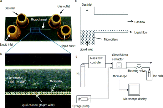
The glass/silicon contactor (Fig. 1a) was fabricated by conventional semiconductor processing techniques. Silicon wafers (n-type, 〈100〉, 525 μm thick) from Compact Technology were pre-cleaned by a Piranha solution (50 vol% H2SO4 and 50 vol% H2O2) at 100 °C for 15 min. After rinsing and drying, a SPR-220-7 photoresist layer (Rohm and Haas) was spin-coated on the wafer for standard photolithography procedure. The dimensions of the microchannel are shown in Table 1. The silicon was etched using deep reactive ion etching (STS ASE). After confirming the depth of the microchannel to be 100 μm by a surface profiler (Veeco Dektak 8), a Corning 7740 glass plate with pre-drilled holes was bonded anodically on the silicon wafer. The bonding was performed at 420 °C on a hot-plate (Stuart SD162) and 1 kV and maintained for 10 min. Nanoport™ fittings (Upchurch) were finally attached for liquid and gas conduits. Arrays of silicon micropillars 10 μm in diameter were formed during the etching process along the liquid conduit (Fig. 1b) in order to induce capillary action. At both end sections of the microchannel, micropillars were also incorporated to prevent gas from passing through the liquid stream (Fig. 1c). During the stripping experiment, acetone–water mixture with known concentration was pumped using a syringe pump (Razel A-99.Fjz) into the liquid conduit of the chip whereas the gas (ultra-high purity nitrogen) flow was co-current and was controlled by a mass flow controller (Brooks 5850). Pressure difference between the two outlets was controlled by a metering valve (Swagelok) at the liquid outlet to prevent breakthrough of one phase to the other. A schematic of the experimental set-up for acetone stripping using the glass/silicon contactor is shown in Fig. 1d.| Dimension | Value (mm) |
|---|---|
| Length | 35 |
| Width of gas channel | 0.195 |
| Width of liquid channel | 0.015 |
| Micropillar diameter | 0.01 |
| Depth of the channel | 0.1 |
In order to compare the separation performance of the microfabricated chip, a PTFE membrane contactor was also used. The contactor comprised a membrane placed between two 18 mm thick acrylic plates (S.I.M, UK), containing inlet and outlet ports for the fluids. One channel was machined in each acrylic plate with 0.85 mm and 0.2 mm depth forming the chambers where gas and liquid flow respectively. Both channels were 5.48 mm wide (see Fig. 2). Two viton gaskets, each 0.5 mm thick (Altec, UK), were placed in 0.4 mm deep grooves machined in the acrylic plates to provide the sealing. The membrane was made from pure PTFE (Teflon) (Sterlitech, US) laminated onto a polypropylene layer. The pure PTFE was 20 μm thick and contained openings approximately 0.5–5 μm in size as observed by scanning electron microscope. The polypropylene layer was 80 μm thick and consisted of holes in an approximately rectangular shape with dimensions of 0.8 × 0.32 mm. The contact area between the two fluids was constrained between the overlapping parts of the gas/liquid channels and was 90 mm × 5.48 mm. Gas and liquid flow rate as well as pressure were controlled as previously.
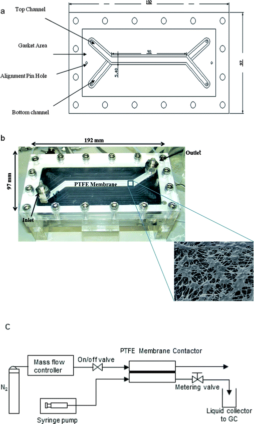 | ||
| Fig. 2 (a) Schematic of PTFE membrane contactor, (b) photograph of the contactor; inset shows an SEM picture of the PTFE membrane, (c) schematic of the experimental set-up. | ||
Liquid samples were taken from the liquid outlet and analyzed by a gas chromatograph (Agilent 6890 with CyclodexB column and thermal conductivity detector). For each experiment, samples were taken at different time intervals until the acetone concentration was constant. This ensured that the experiment was at steady state. All the experiments were carried out at room temperature (approximately 20 °C). After each experiment the contactor was cleaned by flushing with distilled water to avoid any adverse effect of residual acetone on the arcylic plates and the PTFE membrane. A schematic of the experimental set-up is shown in Fig. 2c.
3. Modelling
A model which describes mass transfer of acetone from the liquid phase to the gas phase in co-current flow was formulated under the assumptions of constant gas and liquid flow rates, isothermal conditions and constant mass transfer coefficients. The analytical solution of the model provides the outlet acetone concentration in the liquid phase of the membrane contactor Cout as function of the inlet concentration Cin, the contactor length L and two dimensionless parameters β and Ω:18 ,
,  where Fg and Fl are gas and liquid volumetric flowrates, H, is the Henry's law coefficient (defined as ratio of liquid to gas concentrations), KT, is the total mass transfer coefficient based on the liquid phase, τl, is the liquid (average) residence time, δl, is the liquid channel thickness. The overall mass transfer coefficient was calculated from:21
where kg, kl, km, are the mass transfer coefficients in the gas phase, liquid phase and membrane respectively.
The membrane mass transfer resistance, H/km, depends on the membrane mode operation, i.e. wetting mode or non-wetting mode. The difference between the two modes lies in the expression of the membrane mass transfer coefficient calculations. In case of gas-filled membrane pores,  , while
  for the case of liquid-filled membrane pores. The Henry constant is 1060. It is noted that τ is the tortuosity, ε is the porosity, Dg is the diffusion coefficient of acetone in nitrogen (1.15 × 10⁻⁵ m2 s−1
![[thin space (1/6-em)]](https://www.rsc.org/images/entities/char_2009.gif) 17) and Dl is the diffusion coefficient of acetone in water 1.16 × 10⁻⁹ m2 s−1.22
17) and Dl is the diffusion coefficient of acetone in water 1.16 × 10⁻⁹ m2 s−1.22
When the Graetz number is <20, the flow can be assumed to be fully developed23 and then the Nusselt number has a constant value of 4.86![[thin space (1/6-em)]](https://www.rsc.org/images/entities/char_2009.gif) 24 for one wall transferring heat. Due to heat-mass transfer analogy this would be the same value for the Sherwood number (2kδ/D) and can be used for the calculation of gas and liquid mass transfer coefficients.
24 for one wall transferring heat. Due to heat-mass transfer analogy this would be the same value for the Sherwood number (2kδ/D) and can be used for the calculation of gas and liquid mass transfer coefficients.
4. Results and discussion
4.1. Working principle
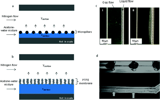
In both contactors the gas and liquid streams are kept separated and flow without interdispersion. Fig. 3 illustrates the working principle. In the glass/silicon contactor (Fig. 3a), micropillars were fabricated in the microchannel. When liquid flowed through the channel, menisci were induced by capillary action. A critical issue in operating the microcontactor is the stability of the gas/liquid interface. If the pressure difference between the phases exceeds a critical value (which is governed by the Young–Laplace equation18), then one phase will break through and disperse into the other phase. Such breakthrough can be controlled by the use of a metering valve on the liquid outlet of the contactor. An optical microscope image in Fig. 3c(i) shows that the gas–liquid interface was well-established during the operation, but if the pressure difference between the phases was not properly balanced, breakthrough was observed (see Fig. 3c(ii)). According to the Laplace equation the distance of micropillars, surface tension, and contact angle affects stability of the interface. In addition, breakthrough is affected by pressure drops of the two fluids, which are in turn influenced by the corresponding channel depth and width, flow rates and flow pattern (co-current flow is more stable than counter-current). It must be pointed out that the liquid film thickness depends on the dimension/location of the micropillars. Fig. 3b shows how the gas–liquid interface is established in the PTFE membrane contactor. The membrane acts as a mechanical barrier to prevent liquid/gas breakthrough, while its ultra-small pores provide numerous channels for the mass transfer process. Fig. 3d shows an experiment where liquid from the bottom liquid phase channel entered the gas phase channel, when increasing the liquid phase pressure beyond the breakthrough point.4.2. Separation of acetone–water mixture
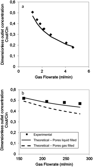
During acetone stripping in the microfabricated contactor, acetone molecules diffused from the acetone–water mixture to the gas stream. By keeping the liquid flow rate constant, the effect of gas flow rate on the separation performance of the microfabricated silicon/glass gas–liquid contactor was investigated. The liquid flow rate (2 M acetone–water mixture) was fixed at 0.001 ml min−1, which corresponded to a residence time of 3.15 s, while the gas flow rate was varied from 1.20 ml min−1 to 4.65 ml min−1, leading to a gas residence time between 0.034 s and 0.01 s respectively. Fig. 4a shows the dimensionless outlet concentration of acetone (i.e. acetone concentration at outlet/acetone concentration at inlet) in the liquid stream against nitrogen gas flow rate. Efficient separation is achieved when this value tends to zero. It is observed that the higher the gas flow rate, the lower the acetone concentration in the liquid stream, implying a better separation. When the gas flow rate increased, the acetone concentration in gas phase was reduced. This increased the concentration gradient, i.e. the driving force, for acetone mass transfer between the liquid and gas phases. It is evident from Fig. 3c that the micropillars were wetted during the experiment. Thus, it is appropriate to apply the model using the assumption of wetting conditions. Experimental data are in good agreement with the analytical model (see Fig. 4a).Acetone stripping performance using the PTFE membrane contactor is summarized in Fig. 4b. It is noted that the concentration of acetone–water mixture used for this experiment is decreased to 1 M due to compatibility problems of acetone and the acrylic material of the membrane module. The PTFE membrane has porosity ca. 70% and tortuosity of 2.6.25 The polypropylene layer of the membrane was on the gas side of the contactor. In order to study the effect of gas flow rate on acetone stripping for the PTFE membrane contactor, experiments were performed by fixing the liquid flow rate at 0.13 ml min−1, corresponding to a residence time of 50 s. The gas flow rate was varied between 160 ml min−1 and 280 ml min−1 that corresponded to gas residence time 0.16 s and 0.091 s respectively. As shown in Fig. 4b, acetone removal increased with increase in carrier gas flow rate. This is similar with the microfabricated chip, although the extent of the effect is much smaller. It implies that the separation is limited by diffusion through the liquid phase. The experimental results are better fitted with the wetted mode (pores assumed liquid-filled) than the non-wetted mode (pores assumed gas-filled). This might be due to the PTFE pores being partially wetted by the liquid phase, resulting in an increase of the mass transfer resistance.
Since the separation performance of stripping contactors depends on the gas to liquid flow rate ratios Fg/Fl (refer to the expression of Ω), the two types of gas–liquid contactors can be better compared by plotting the dimensionless concentration against Fg/Fl. The experiments performed with the PTFE membrane and the glass/silicon contactor with Fg/Fl ratios between 1200 and 2100 are plotted together with the analytical model in Fig. 5. It is clear that the performance of the silicon contactor is better than the PTFE membrane and this difference increases with the increase of the ratio Fg/Fl. For the silicon chip, its mass transfer coefficient is 3.3 × 10⁻⁵ m s−1 which is larger than the mass transfer coefficient 9.4 × 10⁻⁶ m s−1 of the PTFE contactor due primarily to the thinner liquid film in the module. This resulted in a better separation performance. For example, for small residence time of gas and liquid streams, 0.0187 s for gas and 3.15 s for liquid for the microfabricated chip and 0.091 s for gas and 48 s for liquid for the PTFE contactor, separation Cout/Cin = 0.33 for the microfabricated chip and Cout/Cin = 0.52 for the PTFE contactor.
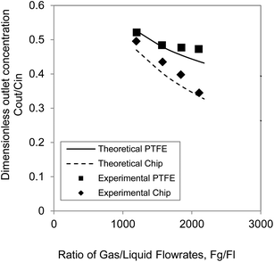 | ||
| Fig. 5 Comparison of the two separators and the respective models in terms of dimensionless outlet concentration of acetone as a function of gas/liquid flow rate ratio. | ||
The performance of the silicon chip is also better as compared to other contactors made from stainless steel or propylene. A stainless steel micro-etched mesh contactor that we have used in previous work,18 where a 50 μm thin mesh stabilized the gas–liquid interface had a total mass transfer coefficient of 2.1 × 10⁻⁶ m s−1). Gascons Viladomat et al.15 who studied air-stripping of aroma compounds in a polypropylene hollow fibre membrane contactor, found total mass transfer coefficients of up to 8 × 10⁻⁶ m s−1, while Mahmud et al.26 who studied air-stripping of chloroform and toluene using microporous polypropylene hollow fibres, found a total mass transfer coefficient for chloroform 9 × 10⁻⁶ m s−1 and for toluene 4.5 × 10⁻⁶ m s−1. In this work the silicon/glass chip has a higher total mass transfer coefficient (3.3 × 10⁻⁵ m s−1). This is attributed to the small thickness of the liquid film and small diameter of the micropillars.
5. Conclusions
A microscale, glass/silicon gas–liquid contactor was developed for stripping of acetone from aqueous solution. The gas–liquid interface is maintained by capillary action induced by micropillars. Parametric studies showed that separation efficiency increased with increasing stripping gas flow rate. The results agreed with a mathematical model based on the assumption of constant gas and liquid flow rates, isothermal conditions and constant mass transfer coefficients. From the comparison of the separation performance of the microfabricated chip and a PTFE microchannel membrane contactor, it was concluded that making the liquid channel very thin results in a significant improvement to the separation because of the increase in mass transfer coefficient. Since the liquid film thickness can be much smaller using the microfabricated chip, it leads to an increase of mass transfer as compared to the PTFE microchannel contactor.References
- P. D. I. Fletcher, S. J. Haswell, E. Pombo-Villar, B. H. Warrington, P. Watts, S. Y. F. Wong and X. Zhang, Tetrahedron, 2002, 58, 4735–4757 CrossRef CAS.
- P. Watts and S. J. Haswell, Chem. Soc. Rev., 2005, 34, 235–246 RSC.
- J.-I. Yoshida, H. Kim and A. Nagaki, ChemSusChem, 2011, 4, 331–340 CrossRef CAS PubMed.
- K. L. Yeung, X. Zhang, W. N. Lau and R. M. Aranda, Catal. Today, 2005, 110, 26–37 CrossRef CAS PubMed.
- S. M. Kwan and K. L. Yeung, Chem. Commun., 2008, 3631–3633 RSC.
- R. L. Hartman, H. R. Sahoo, B. C. Yen and K. F. Jensen, Lab Chip, 2009, 9, 1843–1849 RSC.
- K. F. Lam, E. Cao, E. Sorensen and A. Gavriilidis, Lab Chip, 2011, 11, 1311–1317 RSC.
- K. F. Lam, E. Sorensen and A. Gavriilidis, Chem. Eng. Sci., 2011, 66, 2098–2106 CrossRef CAS PubMed.
- Y. Okubo, T. Maki, N. Aoki, T. Hong Khoo, Y. Ohmukai and K. Mae, Chem. Eng. Sci., 2008, 63, 4070–4077 CrossRef CAS PubMed.
- D. M. Fries, T. Voitl and P. R. von Rohr, Chem. Eng. Technol., 2008, 31, 1182–1187 CrossRef CAS.
- J. Khandurina and A. Guttman, Curr. Opin. Chem. Biol., 2003, 7, 595–602 CrossRef CAS PubMed.
- A. Gavriilidis and J. E. A. Shaw, Microchemical Engineering in Practice: Chapter 6: Separation Units, John Wiley & Son, Inc., New Jersey, 2009, pp. 131–156 Search PubMed.
- H. Mahmud, A. Kumar, R. M. Narbaitz and T. Matsuura, J. Membr. Sci., 2002, 209, 207–219 CrossRef CAS.
- I. Souchon, V. Athès, F.-X. Pierre and M. Marin, Desalination, 2004, 163, 39–46 CrossRef CAS.
- F. Gascons Viladomat, I. Souchon, V. Athès and M. Marin, J. Membr. Sci., 2006, 277, 129–136 CrossRef CAS PubMed.
- S. H. Cypes and J. R. Engstrom, Chem. Eng. J., 2004, 101, 49–56 CrossRef CAS PubMed.
- M. Zanfir, X. Sun and A. Gavriilidis, Ind. Eng. Chem. Res., 2008, 47, 8995–9005 CrossRef CAS.
- X. Sun, A. Constantinou and A. Gavriilidis, Chem. Eng. Process., 2011, 50, 991–997 CrossRef CAS PubMed.
- P. Chasanis, K. M. Kehrmann, J. Kern, R. Zecirovic, M. Grünewald and E. Y. Kenig, Chem. Eng. Process., 2011, 50, 1244–1251 CrossRef CAS PubMed.
- B. Dercks, R. Zecirovic, G. Ruffert, M. P. Grun and M. Grünewald, Chem. Ing. Tech., 2011, 83, 1125–1128 CrossRef CAS.
- M. Mavroudi, S. P. Kaldis and G. P. Sakellaropoulos, J. Membr. Sci., 2006, 272, 103–115 CrossRef CAS PubMed.
- A. I. Toryanik and V. N. Taranenko, J. Struct. Chem., 1987, 28, 714–719 CrossRef.
- A. H. P. Skelland, Diffusional mass transfer. John Wiley & sons, Inc., USA, 1974 Search PubMed.
- R. K. Shah and A. L. London, Laminar flow forced convection in ducts: a source book for compact heat exchanger analytical data, Academic Press, New York, 1978 Search PubMed.
- A. Constantinou, S. Barrass, F. Pronk, T. Bril, D. A. Wenn, J. E. A. Shaw and A. Gavriilidis, Chem. Eng. J., 2012, 207–208, 766–771 CrossRef CAS PubMed.
- H. Mahmud, A. Kumar, R. M. Narbaitz and T. Matsuura, J. Membr. Sci., 2002, 209, 207–219 CrossRef CAS.
| This journal is © The Royal Society of Chemistry 2014 |

