Continuous process technology: a tool for sustainable production
Charlotte
Wiles
*a and
Paul
Watts
b
aChemtrix BV, Chemelot Innovation Park, Geleen, The Netherlands. E-mail: c.wiles@chemtrix.com; Web: http://www.chemtrix.com Tel: +44 (0)1482 466459
bInnoVenton:NMMU Institute for Chemical Technology, Nelson Mandela Metropolitan University, PO Box 77 000, Port Elizabeth, 6031, South Africa. E-mail: paul.watts@nmmu.ac.za; Tel: +27 (0) 41 504 3694
First published on 25th October 2013
Abstract
Reviewing the open literature, the authors give their perspective on if continuous process technology has a role to play in sustainable production within the chemical industry.
What are continuous reactors?
Flow, micro or meso reactors are all names given to devices or modules that facilitate the continuous performance of synthetic reactions or transformations. Emergence of this technology into the mainstream has resulted from the ability to design reactors in order to execute the process of interest, rather than the restrictive historical batch approach of constraining the reaction to fit within the vessel(s) available.1 The technology therefore allows tailoring of the reactor size, and the features contained within in it, to the process and the goal of the investigation. This can be viewed as a deviation from the early stage ‘Lab on a Chip’ research, where miniaturisation of the total reaction system was key2 – here size is determined by the required performance. As such, the technology offers broad spectrum applicability from small-scale feasibility assessment through to large-scale industrial production – enabling users to capitalise on the benefits of making the switch from batch to continuous processing irrespective of the project stage that it is implemented i.e. R&D or production.Why use flow reactors?
The past decade has seen this technology transfer3 from a niche academic application to an accepted industrial technique with proven advantages including:Safety: The small hold-up volume in such systems affords unprecedented control over highly exothermic processes. Furthermore, with no headspace in such reactors there is no accumulation of highly unstable intermediates.4
Speed: Speed relates not only to the ability to intensify processes through the access of ‘novel process windows’, as coined by Hessel et al.,5 but also the rapid reaction interrogation and optimisation that results from the small reaction volumes employed.6 Facilitating the rapid transfer of processes from R&D to production, the technology has been shown to be time and cost efficient.
Efficiency: Due to enhanced heat and mass transfer, flow reactors have the potential to reduce the energy costs associated with performing reactions at a production-scale.7 In addition, the modular nature of the technology enables production volumes to be flexibly increased or decreased in order to meet the current material demands. Modularity also lends itself to the construction of process specific plants whilst maintaining the ability to re-purpose the modules at the end of the compounds lifecycle.
Quality: Owing to the ability determine the effect of parameter changes, such as feed quality, reaction time, reagent ratio's and reaction temperature at the research level, Companies are able to develop robust manufacturing protocols – QbD (Quality by Design).8 Furthermore, flow processes can be readily monitored through the use of in-line analytics9 affording process control which enables specification changes to be identified and resolved, with the affected material segregated – reducing the proportion of material rejected compared to batch technologies.
Types of continuous flow reactors
A wide range of reactor materials have been reported, with the selection being based on the intended application. The user must therefore consider the required chemical compatibility,10 thermal range, pressure requirements and method of activation (i.e. thermal, microwave,11 ultrasound,12 radio frequency,13 photochemical14 and electrochemical15) when selecting a reactor type. With this in mind, reported materials of construction include polymers,16 silicon,17 glass,18 metals19 and ceramics.20 Furthermore, reactor type is also dependent upon the process of interest and the goal of the investigation. For example, with respect to a lab-based assessment it can be sufficient to execute reactions is a simple tubular system. However if the goal of the development is to take a compound to production, then a more strategic approach is required whereby design of a reactor must consider maintenance of reaction characteristics such as mass transfer, heat transfer, reaction time and residence time distribution. Consequently a micro/meso-structured approached is therefore often selected. The technology therefore lays a clear pathway for processes to follow from early stage development through to industrial production.The role of continuous processing in sustainable chemical production
Process intensification (PI) is a key aspect in the development of increasingly sustainable synthetic processes and a key feature of continuous flow reactors is the ability to routinely operate at pressure – which has the advantage of enabling the use of low boiling solvents and reagents at elevated temperatures – facilitating product isolation. Furthermore, the tight parameter control accessible in such systems means that it can be possible to selectively run reactions in the absence of formal protecting groups thus reducing the number of reactions steps and purifications required to access synthetically important compounds. Additionally there is less risk associated with process scale-up. These observations have multiple resource benefits, including more efficient use of time, cost and materials; together with a reduction in waste generated.21That said, in a recent survey of 50 European Companies (69% in France), Pichon22 of MEPI (la Maison Européenne des Procédés Innovants) reported that the primary reason for choosing to implement or investigate flow processing was safety, closely followed by competitiveness and product quality – this is not unsurprising as the cost benefits of these metrics can be readily determined. Interestingly, the ecological impact of processes was ranked as a ‘nice to have’ but not found to currently be a decision maker – a feature that is sure to change over the coming years.
In our previous article in this series,23 we focused on assessing which of the twelve principles of Green Chemistry, as outlined by Anastas et al.24 have the potential to benefit from flow reactor technology. Herein we focus on the technologies application towards the development and execution of sustainable chemical processes25 at both the laboratory and production scale through a series of literature examples.
Safety
When considering intensification of a process reduction of solvent is a common starting point. In batch this can however be problematic and lead to increased dosing times in order to thermally control the target synthetic process. In flow reactors the characteristically high thermal management often means that these dosing limitations can be overcome. Additionally they can enable the performance of exothermic reactions at elevated temperatures whilst maintaining process control. An example of this was recently reported by Roberge and Kappe10 whereby the development of a continuous flow process for the atom efficient synthesis of tetrazoles was disclosed. Using the addition of hydrazoic acid to organic nitriles, the authors were able to exploit the increased process safety associated with flow reactors to efficiently synthesise a series of 5-substituted 1H-tetrazoles (Scheme 1). | ||
| Scheme 1 General schematic illustrating the conditions used for the continuous synthesis of 5-substituted 1H-tetrazoles. | ||
Employing a two feed Sulfinert tube reactor (Uniqsis, UK), the authors reacted a solution of nitrile in NMP–AcOH with a solution of aqueous sodium azide (2.5 eq.). Heating the system to 220 °C, the authors were able to safely generate HN3in situ, obtaining the target tetrazoles in isolated yields ranging from 75 to 98% with reaction times of 5 to 15 min. Compared to analogous batch reactions, the authors commented that flow reactor provided a significantly safer method for the large scale synthesis of tetrazoles as the liquid filled reactor had no headspace. In one example, 18.9 g of a tetrazole (89% yield) was synthesised in a 1 h continuous experiment. The authors have subsequently utilised a flow reactor to investigate the decomposition of 5-benzhydryl-1H-tetrazole to diphenylmethane, employing a reaction temperature of 220 °C and a residence time of 10 min.
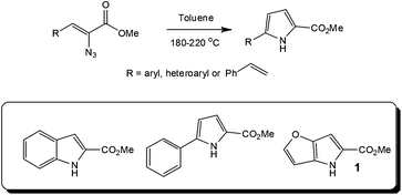
Looking further into the synthesis of hazardous reagents and intermediates, several research groups have evaluated the formation and reaction of azides under flow conditions,26 with the group of Seeberger assessing the thermolysis27 or photolysis28 of aryl azides as a means of accessing efficient and safe techniques for utilising these energetic transformations. In the former case, the authors employed a stainless steel tube reactor (volume = 2 ml; Vapourtec R series) for the high temperature (180 to 220 °C) synthesis of indoles from a series of azidoacrylates. With heterocycles such as the DAAO inhibitor 1 precursor, used in the treatment of schizophrenia, synthesised in high yield (Throughput = 8.5 g in 21 min). Whilst these reactions have found application at a research level, in particular within natural product synthesis, the use of high boiling solvents and sealed tube reactors has previously limited the reactions application at an industrial level (Scheme 2).
On-site production of unstable intermediates
Focusing on the development of a safe production process for per-carboxylic acids, Kolehmainen and co-workers29 of Lappeenranta University of Technology (Finland) assessed the use of a slit-interdigital micromixer. Employing catalytic H2SO4 (6 wt%), the effect of reactor temperature was investigated over the range −5 to 45 °C. Identifying 5 °C as the optimal the authors proposed a design for a compact reaction unit that would be suitable for the on-site production of per-acetic acid at a rate of 20 kg h−1 (23 wt%) – removing the need to transport this hazardous oxidising agent. This is an example where in the future Companies will operate decentralised business models, leading to a reduction in transportation costs and increased safety.Rapid library generation
Looking to the use of alternative activation techniques, Organ et al.30 have a proven track record for the development of microwave-assisted continuous organic syntheses. In a recent example his group explored diversity oriented synthesis (DOS) utilising a multi-capillary reactor – enabling the preparation of a 50-member library of 1,2,5-thiadiazepane 1,1-dioxide derivatives via a one-pot elimination/double aza-Michael strategy. Using this approach, the authors were able to generate the target sultans at the mg-level in yields ranging from 50 to 80%. The materials of interest were then scaled by operating a single capillary reactor for an extended period of time – providing access to 100–300 mg of each material. With the total investigation performed in a period of 2 weeks.Precise reaction control
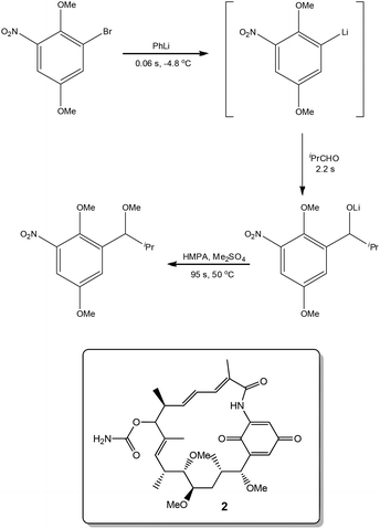
Exploiting the short reaction times accessible in continuous flow devices, Yoshida et al.31 recently demonstrated the synthesis of a key intermediate used in the preparation of the natural product Macbecin I 2. By precisely controlling the reaction times employed for each step, the authors were able to efficiently synthesise the target in 73% overall yield (Scheme 3).Novel synthetic routes
In a second demonstration of superior reaction time control, Kim, Nagaki and Yoshida32 reported the ability to perform organolithium reactions in the presence of carbonyl containing compounds without the need for protection. Using a micro reactor, the authors were able to perform an iodide-lithium exchange with reaction times <0.003 s, followed by reaction of the organolithium derivatives with a range of electrophiles. The methodology was subsequently demonstrated for the synthesis of (Z)-3-(3,5-dimethoxyphenyl)-4,6-dimethoxy-1-(4-methoxybenzylidene)-1,3-dihydroisobenzofuran 3 (81% yield; 212 mg min−1), a key intermediate used in the synthesis of the natural product Pauciflorol F as illustrated in Scheme 4.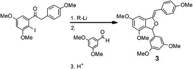 | ||
| Scheme 4 A key iodide–lithium exchange reaction used in the synthesis of a Pauciflorol F intermediate. | ||
Reaction selectivity
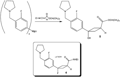
Focusing on the synthesis of a fluorocyclobutane containing H3 antagonist 4, researchers at Pfizer33 identified that the chemoselective addition of a Mg-complex to a keto-ester required tight stoichiometric control, short addition times and low reaction temperatures – the combination of which pointed to the need for a flow process in order to reliably produce the synthetic target (Scheme 5).Utilising a tubular reactor (Vapourtec, UK), the authors employed a reaction temperature of −5 °C and successfully performed the reaction on a 12 g scale (65% yield 5; 4![[thin space (1/6-em)]](https://www.rsc.org/images/entities/char_2009.gif) :
:![[thin space (1/6-em)]](https://www.rsc.org/images/entities/char_2009.gif) 1 5
1 5![[thin space (1/6-em)]](https://www.rsc.org/images/entities/char_2009.gif) :
:![[thin space (1/6-em)]](https://www.rsc.org/images/entities/char_2009.gif) by-product). Based on these positive results, whereby a time consuming and costly 1 h addition time was removed, the authors constructed a kilo-lab apparatus based on a static mixer and assessed the effect of reactor temperature (−25 to 0 °C) for a reaction time of 6–7 min observing excellent product 5 selectivity in all cases. Owing to the fact that ∼5% starting material remained un-reacted at −25 °C, the authors concluded that 0 °C afforded the most optimal temperature – without detrimental effect on product selectivity.
by-product). Based on these positive results, whereby a time consuming and costly 1 h addition time was removed, the authors constructed a kilo-lab apparatus based on a static mixer and assessed the effect of reactor temperature (−25 to 0 °C) for a reaction time of 6–7 min observing excellent product 5 selectivity in all cases. Owing to the fact that ∼5% starting material remained un-reacted at −25 °C, the authors concluded that 0 °C afforded the most optimal temperature – without detrimental effect on product selectivity.
Cost reduction
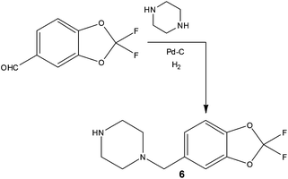
In addition to increasing reaction temperature to reduce processing time, several groups have demonstrated time and cost savings as a result of executing reactions under flow that would previously have required the use of cryogenic conditions. Performing what are termed dosing limited batch reactions, researchers often find that cryogenic conditions combined with dropwise addition of reagents is required in batch to maintain the target selectivity. Owing to the improved thermal performance that flow reactors can exhibit, it has been demonstrated that dosing limitations can be removed and furthermore increased reaction temperatures can be employed thus reducing operating costs. Examples include ionic liquid synthesis,34 lithium-halide exchanges35 and oxidations such as the Swern reaction.36In addition to savings on temperature control, using commercially available hydrogenation apparatus, researchers at Janssen Research and Development demonstrated the preparation of a benzylpiperazine substrate using a direct and scalable reductive amination reaction (Scheme 6).37 Employing inexpensive substrates and Pd–C (10%) in EtOH, the target compound 6 could be prepared at a rate of >100 g day−1, affording facile access the required 300 g of isolated material with an impressive 60% reduction in cost of goods compared to previous batch methods.
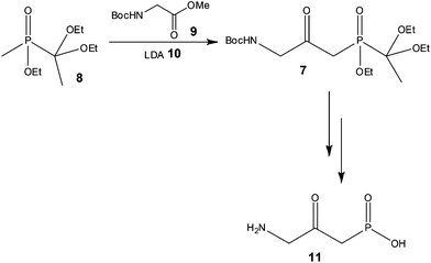
With a view to increasing reaction control, Pontén and co-workers38 demonstrated the advantages of using continuous flow processing at the early stage scale-up of a reflux inhibitor intermediate 7 (Scheme 7), whereby reduced costs of goods and improved product quality were also reported as advantages of the process developed.
Using a 20 ml tube reactor (Vapourtec, UK) and an initial reaction time of 2 min, the authors processed 1.3 kg of 8 (3.4 mol) in 25 h. Isolation of the target compound 7 was however problematic due to the use of excess 9, with purification by chromatography resulting in a variable yield (24 and 54%) of the labile compound. In order to address this problem, the authors investigated the use of 1 equivalent of the N-Boc-glycine methyl ester 9, and were gratified to find that a yield of 58% 7 was obtained with a reaction time of only 90 s. Secondly, the authors observed that the product 7 could tolerate high reaction temperatures for short periods of time and consequently assessed the effect of increasing the reactor temperature from −78 to 35 °C. Using LDA 10 as the base (3 eq.) 1.3 kg of phosphinate 8 was again processed at 35 °C with a reaction time of 90 s affording the target reflux inhibitor AZD6906 11 in 400 g (99% purity) after batch deprotection of 7 and treatment with charcoal.
Reduced operator exposure
With the dual goal of reducing worker exposure and achieving commercial scale production within a laboratory fume cupboard, researchers at Eli Lilly & Company assessed the development of a continuous process for the synthesis of a cytotoxic acyl sulfonamide, Tasisulam 12 (Scheme 8).39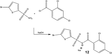 | ||
| Scheme 8 Synthetic strategy employed by Eli Lilly & Company for the continuous production of a cytotoxic compound. | ||
Initial assessments centered on the development of a solubilised batch process whereby triethylamine was replaced by hunigs base; however, this approach was found to yield no advantages over the current batch process. With this in mind, the authors decided rather than operate within the constraints of the batch conditions, to design a process from the outset with flow in mind, consequently it was required that all reagents were solutions at room temperature.
Owing to the high solubility of the target 12 in water, the possibility of using Schotten Baumann conditions was assessed – earlier rejected in batch due to the formation of a significant proportion of a benzoic acid derived by-product. Assessing a series of solvents and bases, the authors revealed a reaction temperature of 65 °C with IPA–H2O–toluene as the solvent system afforded the target compound 12 in 99% conversion – without the need for a phase transfer catalyst. Subsequently, in-line counter-current extraction and continuous crystallisation were explored which led to high levels of impurity rejection. For validation purposes, the production unit was operated at a throughput of 5.2 g h−1.
Application to material production
Although at the various stages of chemical development the goal and focus of particular functions change, for example a medicinal chemist is charged with rapidly preparing NCE's to support toxicological evaluation, often using sub-optimal synthetic routes, at the end point the process R&D chemist is responsible for the smooth transfer of well developed, safe, scalable, robust and economical chemical process to production – across these stages, continuous flow processing has been demonstrated to be applicable. With this in mind, Dach and Roschanger40 of Boehringer Ingelheim Pharma GmbH and Boehringer Ingelheim Pharmaceuticals Inc. respectively wrote an article entitled ‘The Eight Criteria Defining a Good Chemical Manufacturing Process’. Within the article the authors discuss the fact that the past decade has seen API manufacturing costs rise by 20% and this has contributed to the innovation drive experienced by the industry and the target to reduce the number of ‘out of spec’ batches. The goal being to design more robust, viable, cost effective manufacturing processes in early stage development then transferring these processes with minimal change to production. From the examples presented herein, it can be seen that continuous flow processing is one such technology that has the potential to deliver on these targets.Comparison of production costs
Buddoo et al.41 of CSIR Biosciences (South Africa) reported the used of a static mixer for the transesterification of triglycerides derived from vegetable oils to afford fatty acids methyl esters (FAME). Table 1 compares the flow and batch production techniques highlighting impressive potential savings on both capital (24%) and manufacturing (11%) costs for production volumes in the range of twenty thousand tonnes per annum.| Parameter | Batch | Flow | Comment |
|---|---|---|---|
| Plant output (tons year−1) | 20![[thin space (1/6-em)]](https://www.rsc.org/images/entities/char_2009.gif) 000 000 |
20![[thin space (1/6-em)]](https://www.rsc.org/images/entities/char_2009.gif) 000 000 |
— |
| Reactor volume (m3) | 10 | 2.4 × 10⁻³ | 4167× smaller |
| Plant footprint (m2) | 149 | 60 | 60% |
| Surface to volume (m2 m−3) | 14.9 | 2.5 × 10⁻⁴ | 1678× higher |
| Productivity (kg h−1 m−3) | 250 | 10.4 × 10⁻⁵ | 4167× higher |
| Energy input (kJ kg−1) | 7.1 | 0.4 | 18× lower |
| Capital cost (Rm) | 8.6 | 6.5 | 24% saving |
| Manufacturing costs (R/L) | 6.6 | 5.9 | 11% saving |
Owing to the importance of alkyl nitrites as building blocks and reagents in the chemical and pharmaceutical industries, Monbaliu and co-workers42 assessed the use of glass continuous flow reactors (Corning S.A.S.) for their synthesis (Scheme 9).
Currently industrial processes employ the reaction of nitrous acid (aq.) or nitrogen oxides in the presence of nitric acid or oxygen, requiring long reactions times and labour intensive extractions/distillations in order to isolate the alkyl nitrites. With a view to developing an economically viable industrial process, Monbaliu et al. assessed the feasibility of performing such liquid phase reactions under flow, employing HCl and sodium nitrite 13. Using a reaction temperature of 18 °C, with pre-cooled feeds, the authors performed a liquid phase separation at the outlet of the reactor in order to isolate the organic fraction from the aqueous; which was treated with urea to destroy any excess nitrous acid. With a reaction time of 4.8 s the authors were able to isolate isopropylnitrite in >98% purity and >99% conversion cf. 90% for a standard batch processes. Operating the reactor for 24 h illustrated the feasibility of continuous organonitrite synthesis with production capacities in the range of 10 tonnes annum−1.
Continuous downstream processing
Whilst the use of biphasic reaction systems can be viewed as a way to drive reversible reactions in the desired direction, furthermore in the case of rapid and non-reversible reactions the same principle can be exploited as a means of extracting/separating the target analyte from any reaction by-products or catalytic species.Jensen and co-workers43 recently reported the fabrication of a membrane based liquid-liquid separator with integrated pressure control as a means of improving the commonly encountered failure modes for membrane based separators;
1. Breakthrough of retained phase
2. Retention of the permeate phase
Employing pressure control, the authors were able to demonstrate the separation of hexane–water or ethyl acetate–water mixtures (1 to 10 ml min−1) and comment on the use of such a module to facilitate solvent ‘swaps’ which can be required when executing multi-step continuous flow processes whereby telescoping is not applicable.44 Additionally, further research efforts are required into the area of reactive separations, as outlined by Zimmerman et al.45
How to select the right reactor
With clear processing benefits to be gained from the implementation of continuous process technology, several groups have begun to develop methodologies for determining which is the best reactor type for a given process, so called ‘best available technology’ (BAT). One such group is that of de Bellefon,46 who have focused on hydrogenation reactions, with a view to assisting the pharmaceutical industry. Basing their assessment on eight criteria – rate, thermicity, deactivation, solubility, conversion, selectivity, viscosity and catalyst, the model reaction illustrated in Scheme 10 was executed in a stirred batch reactor, CSTR, fixed bed reactor and a falling film reactor. Whilst the approach is in its infancy, comparison of the metrics presented for given reactors does represent an interesting technique for ranking equipment suitability for a given process.When considering process suitability, Hessel et al.47 comment on the fact that the ‘Twelve Principles of Green Chemistry’ allow for qualitative assessment of a processes ‘Green Credentials’ however for a comprehensive assessment it is proposed that Life Cycle Assessment (LCA) is required as a means of determining the environmental burden of a given process. Such an approach requires a high degree of process data and whilst it is more conventionally applied after process development, this could be viewed as being too late as critical decisions have already been taken and criteria fixed. With this in mind, the authors propose that the technique be applied at the R&D stage, via a process known as vertical LCA, to screen the effect of decisions taken at this early stage. An example was given for the Kolbe–Schmidt reaction focusing on the reaction only – however in the future downstream processing should also be considered.48
New areas for application
In addition to the synthesis of small organic molecules, flow reactors are also emerging as tools for the preparation of highly defined nanomaterials. An example of this was reported by Abou-Hassan and co-workers49 who generated high quality CoFe2O4 nanoparticles in only 16 min by connecting two flow reactors together in series. In the first reactor they rapidly homogenised Fe3+ and Co2+ at room temperature to afford precipitates of the respective hydroxides, this was followed by heating to 98 °C upon which aging and evolution of amorphous hydroxides into crystalline CoFe2O4 was observed. Compared to batch processes whereby 10–20 nm particles were prepared, the two-stage flow approach generated particles with an average size of only 5 nm.Employing a Coflore Agitated Cell Reactor (AM Technology), Maggini et al.50 reported the ability to functionalise carbon nanotubes with a diazonium moiety – tailoring the degree of functionalisation as a result of reaction time. Most impressive was the ability to reduce the reaction time from batch of 15 h to 30 min.
In a recent publication, Wong and co-workers51 reported the ability to obtain a series of conjugated polymers in narrow molecular weight distribution and reduced reaction times as a result of performing the transformation in a 10 ml tube reactor (Vapourtec, UK). Using the Suzuki-coupling reaction to construct the polymers, the authors reported the dosing of monomer solutions, Pd-catalyst and an aqueous base into a heated and pressurised (8 bar) system. Employing reaction times of 0.5 to 2 h, the authors were able to obtain the target polymers in 70 to 90% yield with comparable or improved molecular weight distributions. Scheme 11 illustrates a generalised protocol implemented for the synthesis of conjugated polymers – which find application as organic photovoltaics.
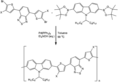 | ||
| Scheme 11 Illustration of a generalised protocol used for the synthesis of conjugated polymers under flow conditions. | ||
In another synthesis utilising thiophenes, Seyler and co-workers52 reported the development of a continuous flow process for the synthesis of organo-electronic dyes affording access, for the first time, to the compounds on a gram-scale.
Outlook & perspective on continuous flow technology for sustainable production
Looking to the fundamental aspects of Green Chemistry, continuous flow technology has been shown to facilitate process intensification,53 provide access to novel synthetic routes,54 lead to improved reaction selectivity,55 reduce downstream processing costs and afford increased process safety.56 However, whilst flow processing is an established technique used in other manufacturing industries such as food and petrochemical, a perceived barrier within the chemical industry, and in particular the pharmaceutical industry, is regarding the technologies disruptive effect on regulatory approval. In a recent article, Gonzalez57 of the US Environmental Protection Agency – Sustainable Technology Division reported positively the advantages that enable the development of sustainable continuous processes are a direct result of the ability to ‘impart a high degree of control on several key reactor and reaction parameters’ and as has been discussed previously this facilities the ability to follow a QbD approach.58Whilst the number of industrial examples utilising flow is increasing, in order to encourage more users to access the benefits that continuous processing has to offer at the reaction and purification stages of material production, more examples of success and failures need to be reported to enable (potential) users to learn from the experiences of others. This not only includes openness regarding the technical challenges/successes but also economic advantages/disadvantages identified.
Conclusion
Compared to stirred reactor vessels, continuous flow reactors have significant processing advantages which include improved thermal management, enhanced mixing control and access to larger operating windows – enabling the development of safe, efficient, robust and sustainable synthetic/production processes. At the production scale, benefits are not limited to increased process safety, but also include the ability to develop more efficient, cost effective processes reducing the downstream processing costs and efforts required.Application at both lab and production scale means that continuous flow reactor technology has the ability to benefit both early stage researchers and process development chemists/engineers, facilitating the development of safe, efficient and sustainable processes.
Notes and references
- S. Hickling and P. Poechlauer, Spectrochim. Chem., 2012, 22–23 Search PubMed.
- R. Daw and J. Finkelstein, Nature, 2006, 442, 367 CrossRef CAS.
- (a) D. T. McQuade and P. H. Seeberger, J. Org. Chem., 2013, 78, 6384–6389 CrossRef CAS PubMed; (b) P. Poechlauer, J. Manley, R. Broxterman, B. Gregertsen and M. Ridemark, Org. Process Res. Dev., 2012, 16, 1586–1590 CrossRef CAS.
- N. Kockmann and D. M. Roberge, Chem. Eng. Technol., 2009, 32, 1682–1694 CrossRef CAS.
- V. Hessel, D. Kralisch, N. Kockmann, T. Noel and Q. Wang, ChemSusChem, 2013, 6, 746–789 CrossRef CAS PubMed.
- (a) R. C. Wheeler, E. Baxter, I. B. Campbell and S. J. F. Macdonald, Org. Process Res. Dev., 2011, 15, 565–569 CrossRef CAS; (b) D. Breuch and H. Löwe, Green Process. Synth., 2012, 1, 261–267 Search PubMed.
- A. Salic and B. Zelic, Goriva i Maziva, 2011, 50, 98–110 Search PubMed.
- (a) J. M. Juran, Juran on Quality by Design, Free Press, 1992 Search PubMed; (b) N. Mantos and M. Gil, Spectrochim. Chem., 2013, 10–13 Search PubMed.
- (a) J. Goode and D. Hebrault, Chem. Today, 2012, 30(60), 20–24 CAS; (b) T. Brodmann, P. Koos, A. Metzger, P. Knochel and S. V. Ley, Org. Process Res. Dev., 2012, 16, 1102–1113 CrossRef CAS.
- B. Gutman, T. N. Glasnov, T. Razzaq, W. Goeddler, D. M. Roberge and C. O. Kappe, Beilstein J. Org. Chem., 2011, 7, 503–517 CrossRef PubMed.
- (a) D. Obermayer, T. N. Glasnov and C. O. Kappe, J. Org. Chem., 2011, 76, 6657–6669 CrossRef CAS PubMed; (b) E. Gjuraj, R. Kongoli and G. Shore, Chem. Biochem. Eng. Q., 2012, 26(3), 285–307 CAS.
- (a) B. Ahmed-Omer, D. Barrow and T. Wirth, Chem. Eng. J., 2008, S280–S283 CrossRef CAS PubMed; (b) J. Sedelmeier, S. V. Ley, I. R. Baxendale and M. Baumann, Org. Lett., 2010, 12(16), 3618–3621 CrossRef CAS PubMed; (c) T. Noël, J. R. Naber, R. L. Hartman, J. P. McMullen, K. F. Jensen and S. L. Buchwald, Chem. Sci., 2011, 2, 287–290 RSC; (d) L. Zhang, M. Geng, P. Teng, D. Zhao, X. Lu and J.-X. Li, Ultrason. Sonochem., 2012, 19, 250–256 CrossRef CAS PubMed.
- S. Ceylan, L. Coutable, J. Wegner and A. Kirschning, Chem.–Eur. J., 2011, 17, 1884–1893 CrossRef CAS PubMed.
- (a) H. Mukae, H. Maeda, S. Nashihara and K. Mizuno, Bull. Chem. Soc. Jpn., 2007, 80(6), 1157–1161 CrossRef CAS; (b) O. Shvydkiv, K. Nolan and M. Oelgemöller, Br. J. Org. Chem., 2011, 7, 1055–1063 CAS; (c) O. Shvydkiv, K. Nolan and M. Oelgemöller, Beilstein J. Org. Chem., 2011, 7, 1055–1063 CrossRef CAS PubMed.
- J. Kuleshova, J. T. Hill-Cousins, P. R. Birkin, R. C. D. Brown, D. Pletcher and T. J. Underwood, Electrochim. Acta, 2011, 56, 4322–4326 CrossRef CAS PubMed.
- R. A. Maurya, C. P. Park and D. P. Kim, Beilstein J. Org. Chem., 2011, 7, 1158–1163 CrossRef CAS PubMed.
- V. Hessel, A. Renken, J. C. Schouten and J. Yoshida, Micro Process Engineering: A Comprehensive Handbook, Chapter 18, Wiley-VCH, 2009 Search PubMed.
- T. Dietrich, A. Freitag and R. Scholz, Chem. Eng. Technol., 2005, 28, 1–7 CrossRef.
- W. Ehrfeld, V. Hessel and V. Haverkamp, Ullmans Encyclopedia of Industrial Chemistry, 2000 Search PubMed.
- (a) F. Meschke, G. Riebler, V. Hessel, J. Schurer and T. Baier, Chem. Eng. Technol., 2005, 28, 465–473 CrossRef CAS; (b) S. Gomez-de Pedro, M. Puyol, D. Izquierdo, I. Salinas, J. M. de la Fuente and J. Alonso-Chamarro, Nanoscale, 2012, 4, 1328–1335 RSC.
- SenterNovem, European Roadmap for Process Intensification-Creative Energy, The Hague, 2007 Search PubMed.
- L. Pichon, 4th Symposium on Continuous Flow Reactor Technology for Industrial Applications, September 2012, Portugal.
- C. Wiles and P. Watts, Green Chem., 2012, 14, 38–54 RSC.
- (a) P. T. Anastas and J. C. Warner, Greem Chemistry – Theory and Practise, Oxford University Press, 2000 Search PubMed; (b) P. T. Anastas and M. M. Kirchhoff, Acc. Chem. Res., 2002, 35, 686–694 CrossRef CAS PubMed.
- J. Yoshida, H. Kim and A. Nagaki, ChemSusChem, 2011, 4(3), 331–340 CrossRef CAS PubMed.
- A. G. O'Brien, F. Lévesque, Y. Suzuki and P. H. Seeberger, Chem. Today, 2011, 29(3), 57–61 CAS.
- A. G. O'Brien, F. Lévesque and P. H. Seeberger, Chem. Commun., 2011, 47, 2688–2690 RSC.
- F. R. Bou-Hamdan, F. Lévesque, A. G. O'Brien and P. H. Seeberger, Br. J. Org. Chem., 2011, 7, 1124–1129 CAS.
- F. Ebrahimi, E. Kolehmainen, P. Oinas, V. Hietapelto and I. Turunen, Chem. Eng. J., 2011, 167, 713–717 CrossRef CAS PubMed.
- F. Ullah, Q. Zang, S. Javed, A. Zhou, C. A. Knudtson, D. Bi, P. R. Hanson and M. G. Organ, J. Flow Chem., 2012, 2(4), 118–123 CrossRef CAS.
- J. Yoshida, H. Kim and A. Nagaki, Angew. Chem., Int. Ed., 2009, 48, 8063–8065 CrossRef PubMed.
- H. Kim, A. Nagaki and J. Yoshida, Nat. Commun., 2011, 2, 264 CrossRef PubMed.
- J. M. Hawkins, P. Dubé, M. T. Maloney, L. Wei, M. Ewing, S. M. Chesnut, J. R. Denette, B. M. Lillie and R. Vaidyanathan, Org. Process Res. Dev., 2012, 16, 1393–1403 CrossRef CAS.
- D. A. Waterkamp, M. Heiland, M. Schluter, J. C. Sauvageau, T. Beyersdorff and J. Thoming, Green Chem., 2007, 9, 1084–1090 RSC.
- (a) B. Liu, Y. Fan, X. Lv, X. Liu, Y. Yang and Y. Jia, Org. Process Res. Dev., 2013, 17(1), 133–137 CrossRef CAS; (b) H. Usutani, Y. Tomida, A. Nagaki, H. Okamoto, T. Nokami and J. Yoshida, J. Am. Chem. Soc., 2007, 129, 3046–3047 CAS.
- (a) P. J. Nieuwland, K. Kock, N. Van Harskamp, R. Wehrens, J. C. M. van Hest and F. P. J. T. Rutjes, Chem. Asian J., 2010, 5, 799–805 CrossRef CAS PubMed; (b) T. Kawaguchi, H. Miyata, K. Ataka, K. Mae and J. Yoshida, Angew. Chem., Int. Ed., 2005, 44, 2413–2416 CrossRef CAS PubMed.
- J. Liu, A. E. Fitzgerald and N. S. Mani, Synthesis, 2012, 2469–2473 CrossRef PubMed.
- T. Gustafsson, H. Sörensen and F. Pontén, Org. Process Res. Dev., 2012, 16, 925–929 CrossRef CAS.
- T. D. White, K. D. Berglund, J. McClary Groh, M. D. Johnson, R. D. Miller and M. H. Yates, Org. Process Res. Dev., 2012, 16, 939–957 CrossRef CAS.
- R. Dach, J. J. Song, F. Roschanger, W. Samstag and C. H. Sennayake, Org. Process Res. Dev., 2012, 16, 1697–1706 CrossRef CAS.
- S. R. Buddoo, Microreactors – A Marvel of Modern Manufacturing Technology: Biodiesel Case Study, 2008 Search PubMed.
- J. C. M. Monbaliu, J. Jorda, B. Chevalier, C. V. Stevens and B. Morvan, Chem. Today, 2011, 29(3), 50–52 CAS.
- A. Adamo, P. L. Heider, N. Weeranoppanant and K. F. Jensen, Ind. Eng. Chem. Res., 2013, 52(31), 10802–10808 CrossRef CAS.
- P. R. D. Murray, D. L. Browne, J. C. Pastre, C. Butters, D. Guthrie and S. V. Ley, Org. Process Res. Dev., 2013 DOI:10.1021/op4001548 ; article in press.
- W. B. Zimmerman, P. O. Mchedlov-Petrossyan and G. A. Khomenko, Chem. Eng. Sci., 2007, 62, 1770–1782 CrossRef CAS PubMed.
- T. V. le Doan, P. Stavánek and C. De Bellefon, J. Flow Chem., 2012, 2(3), 77–82 CrossRef.
- V. Hessel, B. Cortese and M. H. M. M. de Croon, Chem. Eng. Sci., 2011, 66, 1426–1448 CrossRef CAS PubMed.
- S. Kressirer, D. Kralisch, A. Stark, U. Krtschil and V. Hessel, Environ. Sci. Technol., 2013, 47, 5362–5371 CrossRef CAS PubMed.
- A. Abou-Hassan, S. Neveu, V. Supuis and V. Cabuil, RSC Adv., 2012, 2, 11263–11266 RSC.
- M. Maggini and G. Gasparini, Chem. Today, 2012, 30, 37–39 Search PubMed.
- H. Seyler, D. J. Jones, A. B. Holmes and W. W. H. Wong, Chem. Commun., 2011 DOI:10.11039/c1cc14315h.
- H. Seyler, S. Haid, T. H. Kwon, D. J. Jones, P. Bauerle, A. B. Holmes and W. W. H. Wang, Aust. J. Chem., 2012, 66, 151–156 CrossRef.
- (a) A. J. Stankiewicz and J. A. Moulijn, Chem. Eng. Prog., 2000, 22–34 CAS; (b) A. Pohar and I. Plazl, Chem. Biochem. Eng. Q, 2009, 23, 537–544 CAS.
- T. Wirth, Microreactors in Organic Chemistry and Catalysis, Wiley-VCH, 2013 Search PubMed.
- (a) J. De, M. Munoz, J. Alcazar, A. de la Hoz and A. Diaz-Ortiz, Eur. J. Org. Chem., 2012, 260–263 Search PubMed; (b) M. M. E. Delville, J. J. F. van Gool, I. M. van Wijk, J. C. M. van Hest and F. P. J. T. Rutjes, J. Flow Chem., 2012, 2, 124–128 CrossRef CAS; (c) L. Ducry and D. M. Roberge, Org. Process Res. Dev., 2008, 12, 163–167 CrossRef CAS.
- (a) N. G. Anderson, Org. Process Res. Dev., 2012, 16, 852–869 CrossRef CAS; (b) D. M. Roberge, L. Ducry, N. Bieler, P. Cretton and B. Zimmermann, Chem. Eng. Technol., 2005, 28, 318–323 CrossRef CAS.
- M. A. Gonzalez, Chem. Today, 2013, 31(3), 16–21 Search PubMed.
- Pharmaceutical Quality for the 21st Century: A Risk-based Approach, http://www.fda.gov/oc/cgmp/report0507.html.
| This journal is © The Royal Society of Chemistry 2014 |

