Energy: the microfluidic frontier
David
Sinton
*
Department of Mechanical and Industrial Engineering, and Institute for Sustainable Energy, University of Toronto, 5 King's College Road, Toronto, Ontario, Canada M5S 3G8. E-mail: sinton@mie.utoronto.ca; Tel: +1 416 978 1623
First published on 25th April 2014
Abstract
Global energy is largely a fluids problem. It is also large-scale, in stark contrast to microchannels. Microfluidic energy technologies must offer either massive scalability or direct relevance to energy processes already operating at scale. We have to pick our fights. Highlighted here are the exceptional opportunities I see, including some recent successes and areas where much more attention is needed. The most promising directions are those that leverage high surface-to-volume ratios, rapid diffusive transport, capacity for high temperature and high pressure experiments, and length scales characteristic of microbes and fluids (hydrocarbons, CO2) underground. The most immediate areas of application are where information is the product; either fluid sample analysis (e.g. oil analysis); or informing operations (e.g. CO2 transport in microporous media). I'll close with aspects that differentiate energy from traditional microfluidics applications, the uniquely important role of engineering in energy, and some thoughts for the research community forming at the nexus of lab-on-a-chip and energy – a microfluidic frontier.
Introduction
Developed regions enjoy such seamless and reliable access to energy that the sources, scale and complexity of the energy system are largely invisible. That is, convenient interfaces (e.g. the light switch or thermostat or filling station) mask the source. Today's sources of global energy are plotted in Fig. 1, with 87% coming from fossil fuels, 11% from hydroelectric and nuclear and 2% from wind, solar and other renewables.1 The total energy usage per year is staggering, equivalent to ~90 billion barrels of oil (or 2900 barrels per second), or a volume of natural gas of 14![[thin space (1/6-em)]](https://www.rsc.org/images/entities/char_2009.gif) 000 km3 at standard temperature and pressure (STP), or the total annual solar irradiation on an equatorial area of 50
000 km3 at standard temperature and pressure (STP), or the total annual solar irradiation on an equatorial area of 50![[thin space (1/6-em)]](https://www.rsc.org/images/entities/char_2009.gif) 000 km2. Environmental impacts are also hyper-macro, including 35 billion tonnes of CO2 produced annually from current fossil fuel usage, a volume of gas that would occupy 18
000 km2. Environmental impacts are also hyper-macro, including 35 billion tonnes of CO2 produced annually from current fossil fuel usage, a volume of gas that would occupy 18![[thin space (1/6-em)]](https://www.rsc.org/images/entities/char_2009.gif) 000 km3 at STP. My personal carbon footprint is dominated by a very typical amount of air travel, and is roughly 20 tonnes per year – a personal daily output of 27 m3 per day at STP. These hyper-macro lengthscales are in stark contrast with microchannels. Thus in order to have meaningful impact, microfluidic energy technologies must offer either massive scalability or relevance to energy processes already operating at scale.
000 km3 at STP. My personal carbon footprint is dominated by a very typical amount of air travel, and is roughly 20 tonnes per year – a personal daily output of 27 m3 per day at STP. These hyper-macro lengthscales are in stark contrast with microchannels. Thus in order to have meaningful impact, microfluidic energy technologies must offer either massive scalability or relevance to energy processes already operating at scale.
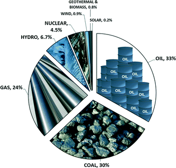 | ||
| Fig. 1 Global energy use by primary source in 2012. Solar and wind values are capacity. Data are from the 2013 BP Statistical Review of World Energy. | ||
The timescales of global energy mirror the large lengthscales: change in global energy comes slowly.1 The history of change in the energy system begins with coal displacing biomass, and then natural gas and petroleum displacing coal. With the benefit of historical perspective it is clear that it requires a timescale of 50–100 years for profoundly disruptive technologies to significantly infiltrate the energy supply. We do not yet have a renewable energy technology with the disruptive potential of say, petroleum (i.e. abundance, energy density, and inherent storage). However, if such a source was discovered today and gained market share at a blistering rate, one could expect it to climb to prominence over a number of decades. While one can hope for more rapid deployment of future technologies, the underlying causes are likely to persist: (i) the massive scale and interconnectedness of global energy (ii) the infrastructure-intensive nature of this business, and (iii) a safety-conscious regulatory environment that entrenches established practices and makes innovation difficult. The importance of developing new renewable technologies, as well as the acknowledgement that these will take many decades to implement, motivates a parallel approach, (i) developing next generation low-carbon energy technologies and (ii) improving the carbon efficiency of existing technologies and utilizing CO2 in the near term. There are many roles for microfluidics on both tacks.
The sections that follow describe energy challenges for which the microfluidics toolkit is well suited, as well as areas that I feel are unsuited. Examples include recent successes as well as applications where much more attention is deserved. I'll close with some differences between energy applications and traditional microfluidics applications, the uniquely important role of engineering in energy, and a few thoughts on the road ahead.
Where does microfluidics fit in the world's largest fluids problem?
In contrast to the microfluidics community, the nanomaterials community have long been active in energy innovation. Their small-scale materials research approach for energy is well-grounded by several factors: (i) the ultimate renewable energy source, solar radiation, having intrinsic lengthscales on the order of 500 nm; (ii) the associated challenge of utilizing solar-energy generated electron–hole pairs locally, prior to recombination; and (iii) efficient electrical energy storage favouring close proximity of conductors in the case of capacitance, and reactants in the case of batteries. Thus several fundamental aspects of the global energy challenge point to innovations from the nanomaterials community. What fundamental aspects of the global energy challenge point to us?First, the global energy challenge is inherently a fluids challenge. Specifically, oil and gas dominate the fossil fuel component, hydro power is fluid power, and nuclear energy operations – while admittedly having atomic energy at their core – are largely devoted to energy conversion from steam. Methods of storing and using energy are also dominated by fluids: fuels, electrochemistry and combustion. The resulting environmental challenges associated with energy use are predominantly fluids problems, from gaseous CO2 emissions from fossil fuel combustion to leaked methane to tailings ponds. Ultimately, the environment is fluid. Fig. 2 provides a graphical overview of the breadth of energy applications suited to microfluidics.
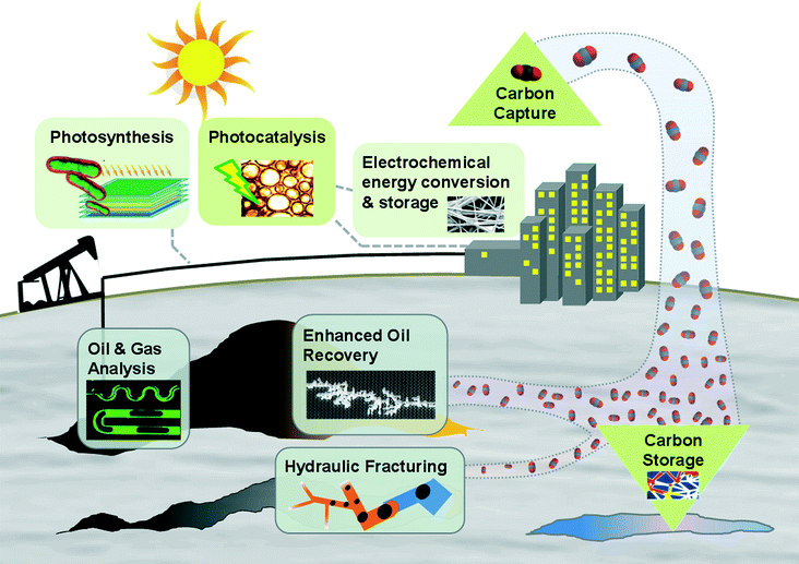 | ||
| Fig. 2 Schematic illustration of the current and envisioned energy applications for microfluidics, including both surface and sub-surface operations. | ||
Second, there are length-scale matches in microfluidics and energy. In the context of globally dominant fossil fuel sources, oil and gas are found exclusively in microporous media. The necessary transport through porous media may be an undesired microfluidic challenge, but it is a microfluidic challenge none the less and one to which microfluidic platforms can contribute. In addition, all energy technologies involving surface-based reactions, electrochemistry and catalysis benefit from high surface-to-volume ratios characteristic of microfluidics. Photosynthetic microorganisms, microalgae, are emerging feedstocks for a range of products including fuels, and the scale of these organisms match those of microfluidics. Lastly, and importantly, traditional strengths of microfluidics in fluid and cellular analysis present tremendous opportunities across the energy spectrum. That is, lab-on-chip technologies providing information (not energy) essential to an energy process. Relevant examples include microreactor arrays to optimize conditions for lipid production from algae, and a massive service industry in oil and gas analysis.
Microfluidics in solar energy – photocatalysis and photosynthesis
While direct solar energy conversion provides only a miniscule fraction of current global usage (Fig. 1), it is the largest potential renewable energy source by a wide margin. In the context of microfluidics, solar energy presents several related opportunities. Fluids and fluidic-lensing can be an effective, and potentially inexpensive, route to capturing solar energy. Such an approach is particularly attractive if the light is ultimately to be used in a fluid-related process, for instance, to drive photocatalysis or photosynthesis in a fluid environment.Photocatalysis can leverage solar energy to drive chemical reactions. While a wide range of applications are relevant, wastewater treatment and the production of valued chemicals, or solar fuels, are prevalent. Processes with surface-based catalysts (heterogeneous catalysis) benefit from high surface-to-volume ratios that favour small length scales and microstructuring. As shown in Fig. 3a, planar lab-on-chip platforms are also useful to characterize photocatalytic surfaces or facilitate light and fluid delivery in porous photocatalytic media as recently demonstrated2 and reviewed.3 Tubular nanostructured TiO2 photocatalysts for solar fuel generation4 present additional exciting opportunities. Analogous to improved sensing with flow-through photonic structures, a flow-through tubular photocatalytic structure array could enable enhanced transport of both reactants and electron–hole pairs.
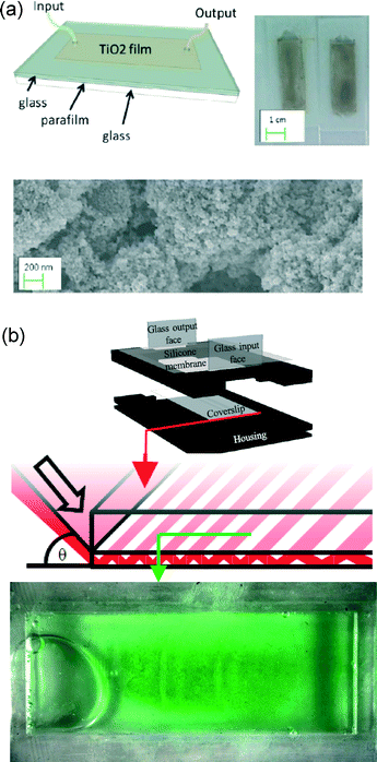 | ||
| Fig. 3 Microfluidics for photocatalysis and photosynthesis. (a) An optofluidic microreactor for redox-mediated photocatalytic water splitting. The device schematic and image are shown above an SEM of the thin film porous microstructure. [Reproduced from ref. 2 with permission from The Royal Society of Chemistry] (b) An optofluidic reactor for the cultivation of photosynthetic bacteria in response to red light, delivered through a thin waveguide with the resulting biofilm grown over 7 cm2, shown below. [Reproduced from ref. 6 with permission of IOP Publishing]. | ||
Photosynthesis presents an opportunity to convert excess CO2 directly into energy-dense liquid fuels that are the global energy carrier of choice (Fig. 1). Biofuels also provide inherent storage, a weakness of all other renewables with the exception of hydropower. In a microfluidic context, photosynthetic bacteria and algae – emerging biofuel feedstocks – are fundamentally microscale. These organisms are also surprisingly fussy in terms of light and fluid conditions, making them good candidates for production optimization via small scale optics and fluidics, as discussed in our recent review.5 These attributes motivate dense microstructured reactors with waveguides and fluid delivery on the scale of biofilms, as exemplified in Fig. 3b.6 Such systems can cater to the microbes' specific tastes in light (wavelengths, intensities, blink frequencies, day/night cycles) and fluid (CO2 and O2 concentrations and pH).7,8 It is also possible to generate electricity directly using these biofilms, employing a plasmonic substrate to both deliver photons and collect electrons produced from photosynthesis.9
The challenge ahead for both photocatalytic- and photosynthesis-based microfluidics is cost. In the absence of a significant financial incentive to reduce CO2 emissions, and with competition from plentiful and cheap fossil fuels, the cost ceiling for all such technologies is very low. Just as the low cost tolerance of public health applications motivated a shift from channel-based to paper-based microfluidics, practical energy producing microfluidic technologies will not involve isolated channels in chips. Being largely solid material by volume (i.e. plastic and not fluid), chips cost too much and the volumetric efficiency is low. Rather, the challenge is to build microfluidic functionality with fluid physics ingenuity and ultra-cheap materials. In the limiting case where an application cannot afford materials, what is left? Fluid. Indeed it is hard to envision a reactor, without the reactor, but I'm excited by the prospect for innovation here. Surface tension and multiphase physics are clear allies in this regard, enabling compartmentalization of reactants as well as waveguiding functionality in a microstructured, highly scaleable, all-fluid-reactor.
An attractive venue for traditional microfluidic chip technologies in photocatalytic and photosynthetic energy conversion, is in screening conditions. That is, where the product of the microfluidic process is information relevant to existing reactor technologies. The many-variable dependencies noted earlier and a lack of current approaches presents a tremendous opportunity for screening. Nice recent examples include an illuminated 96-well plate10 and a 64-reactor array11 to screen conditions for algae. Much more is needed. To chip away at the six or more independent light/fluid variables will require at least 1000s of parallel microreactors – a task exclusively well-suited to our community. There are also exciting opportunities to probe photosynthetic function at the cellular, and sub-cellular level. I am also very interested in traditional microfluidics informing downstream bioenergy operations. Specifically, the conversion of biomass into oil via hydrothermal liquefaction is a rapidly emerging strategy to convert wet biomass into oil at impressive conversion rates (e.g. T ~ 450 °C, P ~ 40 MPa, heating rate ~200 °C min−1 and biocrude yield ~65%).12 High temperature and high pressure microfluidic systems are uniquely well suited to advance this technology through direct and rapid screening for biocrude formation as a function of feedstocks and running conditions.
Microfluidics in electrochemical energy conversion and storage – fuel cells and batteries
Electrochemical reactions at electrode surfaces benefit from high surface-to-volume ratios and short diffusion lengths offered by microstructured electrodes. Traditional hydrogen fuel cells are large-scale units that depend on multiphase transport in microporous electrodes. The application of microfluidic methods has enabled increased understanding of liquid water transport in fuel cells and the role of media properties and history.13Microfluidic fuel cells produce electrical power through co-laminar flow of liquid fuel and oxidant streams,14,15 in contrast to conventional fuel cells that employ an ion exchange membrane. Elimination of the membrane reduces cost and system complexity. Microfluidic fuel cells have made significant advances, including air-breathing cathodes, and flow-through porous electrodes.16Fig. 4a shows a microfluidic fuel cell with flow-through electrodes that provides high fuel utilization, high power density, and the opportunity for reverse-flow recharge. Dense integration and scale-up of such cells is the next stage.
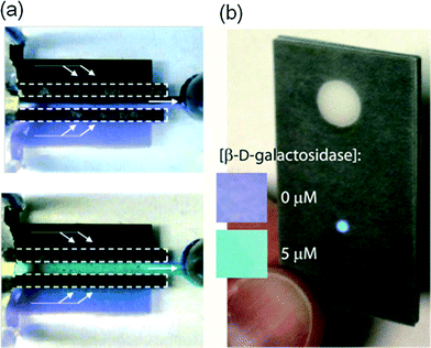 | ||
| Fig. 4 Microfluidics for electrochemical energy conversion and storage. (a) A microfluidic fuel cell with flow-through porous electrodes in stand-by (open circuit), above, and 0.8 V cell voltage, below. The vanadium electrolytes contain V2+ (purple) and V3+ (light green) at the anode, and VO2+ (black) and VO2+ (turquoise) at the cathode. [Reprinted with permission from ref. 16. Copyright 2008 American Chemical Society] (b) Paper-based microfluidic battery in operation, powering an LED readout with intensity indicating the concentration of β-D-galactosidase. [Reproduced from ref. 18 with permission from The Royal Society of Chemistry]. | ||
Integrating existing battery technologies to provide for LOC power needs in remote locations has long been of interest. More recently, however, elegant microfluidic approaches have been developed including a fully rechargeable microfluidic redox battery.17Fig. 4b shows a clever paper-based galvanic cell incorporated into a paper-based assay that turns on with wetting and powers integrated optics.18 Electrochromic read-out and electrochemical sensing have also been powered by an integrated in-paper battery.19 Other new battery technologies also incorporate micro/nanofluidic transport aspects, such as lithium–air and lithium–sulfur batteries.20
Looking forward, increasing the share of intermittent electricity-generating renewables (wind and solar) necessitates improvements in energy storage. Electrochemistry will play a central role. The fundamental benefits of flow-through microstructured electrodes, will drive microfluidics innovation in this area on the long term – targeting electrical energy storage and conversion solutions at all scales. It is likely that the most impactful work in this area will target the imminent need for large-scale energy storage. Thus we need to remember that while the diffusive transport must be small-scale, the application need not be.
Microfluidics for oil and gas
The oil and gas sectors present tremendous opportunities for microfluidics, both via informing their sub-surface operations and via fluid property analysis (either at the surface, or ‘down-hole’). Both approaches offer potential economic and environmental gains proportional to the massive scale of these industries.Although the term ‘reservoir’ conjures images of large open pools of fluids, oil and gas reside in micro- and nano-scale pores in rock. Microfluidic networks can offer unprecedented pore-scale resolution of the critical transport phenomena there. Interestingly, this is a microfluidic approach that far predates microfluidics. So called micromodels – essentially microfluidic chips with flow geometries matching those in porous media – have long been applied in this field. In the 1970s Bonnet and Lenormand21 constructed a microfluidic network using photoresist processes generally associated with microfluidics' emergence decades later. Combined with current fabrication and quantitative imaging methods, micromodels can provide unprecedented pore-scale quantification of fluid phase dynamics and chemistry with reservoir-matched temperatures, pressures, fluids, and geometries. The result is a welcome window into otherwise inaccessible, opaque processes deep underground. Relevant recent LOC applications include conventional oil recovery,22 and the very Canadian steam-assisted recovery of extra heavy oil highlighted in Fig. 5a.23 Looking ahead, there are opportunities to extract much more information by leveraging the full suite of quantitative fluorescence imaging and spectroscopy tools available in microfluidics labs and even fully three-dimensional micromodels.24 Crude oil naturally exhibits fluorescence, which is useful both for visualization (Fig. 5a)23 and potentially probing fluid properties. Fully developing these approaches could reveal the oil recovery killer-app: porescale chemistry and wetting dynamics at the oil front – a literal microfluidic frontier.
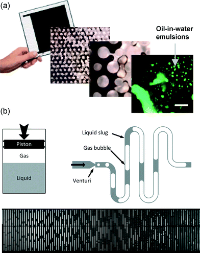 | ||
| Fig. 5 Microfluidics for oil and gas. (a) Micromodel approach to study emulsion formation as a function of additives in extra heavy oil recovery. [Reproduced from ref. 23 with permission from The Royal Society of Chemistry] (b) Microfluidic version of the classical pressure–volume–temperature cell, applied to measure phase dynamics of reservoir fluids [Reproduced from ref. 28 with permission from The Royal Society of Chemistry]. | ||
Although micromodels have a lasting role to play in informing oil and gas operators, oil and gas service companies see the most potential for lab-on-chip technologies in fluid analysis. The incumbent technology is the Pressure–Volume–Temperature (PVT) cell. These expensive and heavily instrumented pressure vessels (100–500 mL) are the workhorses of oil and gas fluid property analysis. Performing such analysis on-chip brings the benefits familiar to LOC technologies: speed, compactness, control over temperature, pressure and concentration, capacity for high pressures, and low sample volumes. Interestingly, the latter is of more interest than one might expect due to the cost associated with retrieving samples. That is, even though the inherent value of crude oil or gas is low, the cost to operators in obtaining and preparing a relevant sample can be very high. Early LOC approaches include microfluidics to measure thin oil film stability,25 CO2–oil diffusivity26 and solvent–oil diffusivity.27 These diffusion measurements provided a 100-fold speed improvement over conventional PVT, and the highest resolution for such measurements to date. There have also been excellent contributions in this area from leading industry labs. Fig. 5b highlights an important work of Mostowfi et al.28 using on-chip phase analysis to study reservoir fluids (analogous to their expansion as they travel from the reservoir to the surface), and related gas-to-oil ratios.29 Another example is on-chip asphaltene quantification.30 There are as many great opportunities as there are fluids and fluid properties of interest to the sector. For fluids these include: density (‘API gravity’ in the industry), viscosity, dew point and bubble point. For fluid pairs it is diffusivity, solubility, and minimum miscibility pressure that are of most interest. Factor into these measurements pressure dependence, temperature dependence, and reservoir-to-reservoir variability and a lifetime of impactful microfluidic innovation awaits.
Hydraulic fracturing in the US has led to recent dramatic changes the oil and gas industry.31 The ability to tap previously unrecoverable oil and gas from ‘tight’ shale formations with nanoscale pores has reshaped the global energy landscape. US production is still less than half of the 18.5 million barrels of oil per day consumed, with Canada being the largest source for the remainder. The rate of change, however, is impressive. US oil production is bucking the longstanding ‘peak oil’ trajectory, and CO2 emissions have reduced markedly with fractured gas displacing coal. Shale energy recovery is enabled by the ability to (i) drill horizontally through thin shale formations, and (ii) locally and directionally fracture the rock to release hydrocarbons. Fracturing – referred to as ‘fracking’ in the media and ‘fracing’ in the industry – is achieved by tremendous fluid pressure (P > 50 MPa) with the resulting cracks being held open by microparticles called proppants (D = 100 μm to 1 mm). The choice of injection fluid depends on the depth (and associated pressure) of the formation, with the deepest formations requiring low-viscosity ‘slickwater’. More shallow formations can use higher viscosity foams or gels that better transport proppant. These thick injection fluids may be subsequently thinned (‘broken’) in situ to allow flow back to the surface. Underneath this cowboy-culture terminology is a dazzlingly complex micro/nanofluidic process, and arguably the most important new energy technology of our time.
Microfluidics is well suited to address many unanswered questions surrounding hydraulic fracturing. For instance, at relevant reservoir temperatures, pressures, and micro/nanoscale fracture/pore geometries: (a) How are proppants transported and fixed?; (c) Why is so little of the initial fracturing fluid recovered?; (d) How can recovered fracture fluid be safely recycled, stored, or decontaminated? (e) What are the dominant transport modes for hydrocarbon mixtures through nanoporous shale? (f) How can operators maximize recovery of valuable liquids (butane, propane) relative to less valuable natural gas (methane); (g) How do observed recovery decline curves relate to what is happening in the subsurface?; (h) What is the net rate of leakage of methane, a powerful greenhouse gas? The LOC toolbox has much to offer in answering these questions. Specifically, transport in fractures is microfluidic and well-suited to micromodels. Transport in the native shale is nanofluidic, and well-suited to nanofabricated high pressure and temperature glass-silicon chips. In summary, hydraulic fracturing is a new, disruptive, divisive, globally-significant energy technology based on extreme micro/nanoscale fluid transport – a call to action for the microfluidics community.
Microfluidics for carbon management
Human progress mirrors energy availability and our modern world was built, almost exclusively, on fossil fuels (Fig. 1). For better or for worse, there is a lot left. Reserves-to-production ratios have remained mostly flat for decades, indicating that available reserves of oil, coal and natural gas are growing in step with consumption. Hydraulic fracturing is exemplary of how new technology turns resources into reserves. Reserves of coal and natural gas are so plentiful the climate implications of their usage far outweigh concern regarding supply (i.e. we have a dangerous amount available).Nature stores carbon underground in the form of fossil fuels. Thus capturing emitted carbon and putting it back underground – carbon sequestration – has a certain logic. Microfluidics has an important role to play in addressing concerns of both the public and operators regarding the transport, reactivity and ultimate safety of injected CO2. Fig. 6a highlights pore-scale CO2 transport and salt formation dynamics typical of CO2 sequestration (called well-bore dryout in industry) quantified for the first time via microfluidics.32
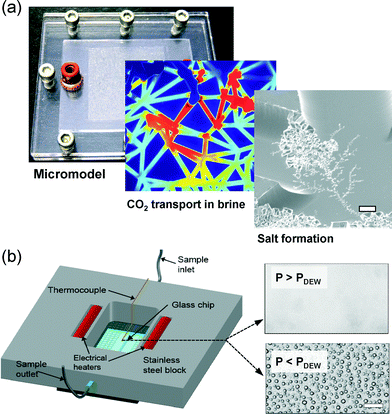 | ||
| Fig. 6 Microfluidics for carbon management. (a) Micromodel approach to study CO2 transport in a saline aquifer and resulting salt precipitation dynamics (scale bar is 10 μm) [Reproduced from ref. 32 with permission from The Royal Society of Chemistry]. (b) Temperature and pressure controlled chip to determine the dew point of hydrated CO2 mixtures with trace impurities from oxy-fuel combustion (scale bar is 10 μm) [Reprinted (adapted) with permission from ref. 33, copyright 2014 American Chemical Society.] | ||
Similar to nuclear energy, carbon capture and storage is both a capital-intensive technology and a political hot-button. In the absence of definitive action on CO2, the future for carbon sequestration is uncertain and somewhat divorced from technological and environmental potential. CO2-based enhanced oil recovery is an intermediate – and feasible – step towards carbon management. The industry is financing expensive and much-needed CO2 capture and transport infrastructure. Microfluidics has a role to play in informing this technology, both through micromodels and LOCs to analyze the miscibility of oil and CO2 phases as a function of operating conditions, CO2 purity and additives. Such approaches will quantify the dynamics of CO2 transport in oil fields and in enable screening of CO2 thickening additives proposed to improve conformance control. While clearly a middle-ground approach in terms of energy and environment, CO2 enhanced oil recovery works. The many microfluidic opportunities here deserve more attention.
There are additional microfluidic opportunities related CO2 infrastructure such as pipelines. A recent example is an LOC approach to detect the dew point of hydrated, industrially relevant CO2 mixtures at pipeline conditions, as highlighted in Fig. 6b.33 Liquid water formation in CO2 pipelines is particularly concerning as it forms a corrosive river of acid within the high pressure vessel. The microfluidic approach offered 3-fold improvement in precision over existing methods, and tested conditions up to 14 MPa and 50 C.
Microfluidics in other energy sources – nuclear hydro and wind
While the above areas detail what I expect are the most impactful targets for the microfluidics community in the energy sector. There are undoubtedly many other opportunities elsewhere in this massive industry. For instance, the scale of the nuclear reactor plants and the many fluids-related operations involved present untapped opportunities for microfluidics, predominantly in fluid monitoring and spent fuel analysis. Microconfinement, fluid control and low sample requirements are well suited to this sensitive application. A commendable first effort along these lines is the application of centrifugal microfluidics to radiochemistry analysis of nuclear spent fuels.34Hydroelectric power – the generation of power leveraging the gravitational potential energy of water – is an attractive renewable energy source. Hydro provides inherent energy storage that is unique among renewables and it enables utilities to buffer the intermittency of other renewables. While hydroelectricity is decisively a macro-scale technology, there may be opportunities related to associated environmental issues. For example, environmental analysis of reservoirs as informed by fluid testing is of ongoing importance, and microfluidics could also inform the particulate sedimentation processes that threaten hydro operations worldwide. In principle, the electrokinetics-based streaming current/potential generated in microchannels can be considered a form of micro/nanofluidic hydropower.35 Although fundamental limits on the efficiency render the approach niche, new additions to this area surface every few years, and will continue to do so.
Lastly, wind energy has seen tremendous growth to date, with levels approaching 1% of the energy supply. It is very difficult, however, to make a practical argument for small scale wind technologies. Wind energy generation favours larger scales exclusively – the bigger the better – and our community should focus on the many energy applications described above, where the fit is strong.
Goodbye plastics, hello (again) silicon and glass
The transition from silicon and glass based microfluidics to plastics in the late 90s resulted in a surge of innovation, and enabled massive growth in microfluidics over the subsequent decade. Plastics are unsuitable, however, for a majority of energy applications outlined above. In the context of solar technologies, the low cost of plastics is welcome, but absorption of valuable ultraviolet light can be an issue. In the context of electrochemical technologies, chemical compatibility and gas permeability of commonly used plastics present challenges. Especially in oil and gas applications where reservoir-relevant conditions require high temperatures/pressures and volatile fluids, silicon and glass-based microfluidics are a necessity (roughly, subsurface temperatures increase at 30 °C km−1 and pressures increase according to the specific weight of water, γ ~ 10 N m−3 = 10 MPa km−1). Fortunately silicon and glass microreactor technologies are well developed in the context of LOC chemical reactors.The supporting infrastructure in a microfluidics-for-energy lab is also a departure from common practices. Where a traditional microfluidics lab might use a syringe pump, peek tubing, and epoxy, microfluidics for energy projects require a temperature controlled high pressure pump, stainless steel tubing within a waterbath-fed jacket, and a machined steel world-to-chip manifold. Although tooling up for energy research requires investment, it is a small admission price to access a huge and comparatively untouched research arena – an unparalleled growth opportunity.
Related to aspects that differentiate microfluidics for energy applications, a last note here on dissemination. Working in microfluidics-for-energy it can be difficult to know which community to target for publications and conferences: Target the energy community and communicate the value of a microfluidic approach?; or target the microfluidics community and communicate the value/context of an energy application? Both are needed. Within the microfluidics community, Lab-on-a-Chip offers wide readership (including many in the energy industry) and is very receptive to new applications and particularly new LOC markets in energy. Within the energy community there are many options but no single obvious choice, perhaps indicating an opportunity.
Engineers are the clinicians of energy
A wonderfully diverse mix of disciplines make up the LOC community. While there are roles for all these disciplines in energy applications, it is notable that energy is an engineering-intensive arena. In traditional microfluidics applications, a typical research proposal would involve engineers/scientists developing a medical LOC technology in partnership with a clinician who grounds – and to some extent validates – the effort. Energy projects, however, present a different model where the technology developers are also the practitioners. In short, engineers are the clinicians of energy. The same is true with respect to interactions with industry. Energy companies have an appreciation of engineering at all ranks – a rarity in other sectors.While engineers within the LOC community may welcome the engineering-intensive nature of energy, it also contributes, I believe, to the conservative nature of this sector as noted earlier. The role of chief clinician also comes with a great deal of responsibility. Global energy challenges are engineering's problem first. There is much more we could be doing.
Conclusions
Energy underpins all aspects of modern life. Energy use is directly correlated with broad measures of societal health including the human development index, and female life expectance at birth – more is more. The scale and importance of global energy use are matched only by the associated environmental impacts. There are important opportunities for the LOC community here.The most exciting opportunities outlined above take advantage of high surface-to-volume ratios, rapid diffusive transport, capacity for high temperature and high pressure experiments, and length scales characteristic of microbes and fluids underground. These include facilitating and informing photosynthetic and photocatalytic processes, developing next generation electrochemical energy conversion and storage methods, and addressing the massive suite of challenges and opportunities surrounding fluids (hydrocarbons and CO2) underground.
In closing, microfluidics can bring a great deal to the world's largest fluids problem. There are vast opportunities on this microfluidic frontier, and much to be done for our collective energy future.
Acknowledgements
The author gratefully acknowledges the generosity of the McLean Family through the 2013 University of Toronto McLean Senior Fellowship. The support of Carbon Management Canada (B-04), Canadian Foundation for Innovation (CFI) and ongoing support from the Natural Sciences and Engineering Research Council of Canada (NSERC) through Discovery and Strategic Project grants is also gratefully acknowledged.Notes and references
- S. Chu and A. Majumdar, Nature, 2012, 488, 294–303 CrossRef CAS PubMed.
- S. S. Ahsan, A. Gumus and D. Erickson, Lab Chip, 2013, 13, 409–414 RSC.
- N. Wang, X. Zhang, Y. Wang, W. Yu and H. L. W. Chan, Lab Chip, 2014, 14, 1074–1082 RSC.
- S. C. Roy, O. K. Varghese, M. Paulose and C. A. Grimes, ACS Nano, 2010, 4, 1259–1278 CrossRef CAS PubMed.
- D. Erickson, D. Sinton and D. Psaltis, Nat. Photonics, 2011, 5, 583–590 CrossRef CAS.
- S. Pierobon, M. Ooms and D. Sinton, J. Micromech. Microeng., 2014, 24, 045017 CrossRef.
- M. D. Ooms, L. Bajin and D. Sinton, Appl. Phys. Lett., 2012, 101, 253701 CrossRef PubMed.
- E. E. Jung, M. Kalontarov, D. F. R. Doud, M. D. Ooms, L. T. Angenent, D. Sinton and D. Erickson, Lab Chip, 2012, 12, 3740–3745 RSC.
- N. Samsonoff, M. D. Ooms and D. Sinton, Appl. Phys. Lett., 2014, 104, 043704 CrossRef PubMed.
- M. Chen, T. Mertiri, T. Holland and A. S. Basu, Lab Chip, 2012, 12, 3870–3874 RSC.
- H. S. Kim, T. L. Weiss, H. R. Thapa, T. P. Devarenne and A. Han, Lab Chip, 2014, 8–13 Search PubMed.
- P. J. Valdez, M. C. Nelson, H. Y. Wang, X. N. Lin and P. E. Savage, Biomass Bioenergy, 2012, 46, 317–331 CrossRef CAS PubMed.
- A. Bazylak, Int. J. Hydrogen Energy, 2009, 34, 3845–3857 CrossRef CAS PubMed.
- M. A. Goulet and E. Kjeang, J. Power Sources, 2014, 260, 186–196 CrossRef CAS PubMed.
- R. Ferrigno, A. D. Stroock, T. D. Clark, M. Mayer and G. M. Whitesides, J. Am. Chem. Soc., 2002, 124, 12930–12931 CrossRef CAS PubMed.
- E. Kjeang, R. Michel, D. A. Harrington, N. Djilali and D. Sinton, J. Am. Chem. Soc., 2008, 130, 4000–4006 CrossRef CAS PubMed.
- J. W. Lee, M.-A. Goulet and E. Kjeang, Lab Chip, 2013, 13, 2504–2507 RSC.
- N. K. Thom, K. Yeung, M. B. Pillion and S. T. Phillips, Lab Chip, 2012, 12, 1768–1770 RSC.
- H. Liu and R. M. Crooks, Anal. Chem., 2012, 84, 2528–2532 CrossRef CAS PubMed.
- N. Mahmood, C. Zhang, H. Yin and Y. Hou, J. Mater. Chem. A, 2014, 2, 15–32 CAS.
- J. Bonnet and R. Lenormand, Rev. Inst. Fr. Pet., 1977, 42, 477–480 Search PubMed.
- N. S. K. Gunda, B. Bera, N. K. Karadimitriou, S. K. Mitra and S. M. Hassanizadeh, Lab Chip, 2011, 11, 3785–3792 RSC.
- T. W. de Haas, H. Fadaei, U. Guerrero and D. Sinton, Lab Chip, 2013, 13, 3832–3839 RSC.
- S. S. Datta, H. Chiang, T. S. Ramakrishnan and D. A. Weitz, Phys. Rev. Lett., 2013, 111, 064501 CrossRef.
- F. Mostowfi, K. Khristov, J. Czarnecki, J. Masliyah and S. Bhattacharjee, Appl. Phys. Lett., 2007, 90, 184102 CrossRef PubMed.
- H. Fadaei, B. Scar and D. Sinton, Energy Fuels, 2011, 25, 4829–4835 CrossRef CAS.
- H. Fadaei, J. M. Shaw and D. Sinton, Energy Fuels, 2013, 27, 2042–2048 CrossRef CAS.
- F. Mostowfi, S. Molla and P. Tabeling, Lab Chip, 2012, 12, 4381–4387 RSC.
- R. Fisher, M. K. Shah, D. Eskin, K. Schmidt, A. Singh, S. Molla and F. Mostowfi, Lab Chip, 2013, 13, 2623–2633 RSC.
- M. H. Schneider, V. J. Sieben, A. M. Kharrat and F. Mostowfi, Anal. Chem., 2013, 85, 5153–5160 CrossRef CAS PubMed.
- G. E. King, in Proceedings of SPE Hydraulic Fracturing Technology Conference, Society of Petroleum Engineers, 2012, SPE paper 152596 Search PubMed.
- M. Kim, A. Sell and D. Sinton, Lab Chip, 2013, 13, 2508–2518 RSC.
- W. Song, H. Fadaei and D. Sinton, Environ. Sci. Technol., 2014, 48(6), 3567–3574 CrossRef CAS PubMed.
- A. Bruchet, V. Taniga, S. Descroix, L. Malaquin, F. Goutelard and C. Mariet, Talanta, 2013, 116, 488–494 CrossRef CAS PubMed.
- H. Daiguji, P. Yang, A. J. Szeri and A. Majumdar, Nano Lett., 2004, 4, 2315–2321 CrossRef CAS.
| This journal is © The Royal Society of Chemistry 2014 |
