Facile synthesis of hierarchical conducting polypyrrole nanostructures via a reactive template of MnO2 and their application in supercapacitors†
Jian-Gan
Wang
*ac,
Bingqing
Wei
ab and
Feiyu
Kang
*c
aSchool of Materials Sciences and Engineering, Northwest Polytechnical University, Xi'an 710072, China. E-mail: wangjiangan@nwpu.edu.cn; Fax: +86 29 8846 0361; Tel: +86 29 8846 0361
bDepartment of Mechanical Engineering, University of Delaware, Newark, DE19716, USA
cSchool of Materials Sciences and Engineering, Tsinghua University, Beijing 100084, China. E-mail: fykang@tsinghua.edu.cn
First published on 11th November 2013
Abstract
We report an eco-friendly and one-step route for the chemical synthesis of hierarchical conducting polypyrrole (PPy) nanostructures via a reactive template of MnO2. The as-prepared PPy nanotubes are found to show good electrical conductivity and superior electrochemical properties for supercapacitor applications.
Conducting polymers have attracted considerable attention in areas of chemistry and materials science for novel technologies because of their unique π-conjugated structure and switchable conductivity between insulator and metal.1–3 Over the past decades, one-dimensional (1D) and three-dimensional (3D) nanostructures made of conducting polymers have been explored extensively. Compared with bulk counterparts, the nanostructural versatility endows these polymers with attractive physiochemical properties which find promising applications in molecular electronics, optics, catalysis, energy storage and biodiagnostics.4,5 Among various conducting polymers, polypyrrole (PPy) is one practically developed system owing to its inherent characteristics of good conductivity, redox properties, environmental stability and hitherto a large variety of applications.6 In particular, the fabrication of 1D hollow nanostructures (e.g. nanotubes) and 3D nano/micro hierarchical structures (e.g. flower-like or urchin-shape spheres) has been a rather challenging issue. For 1D nanotubular PPy, two commonly used approaches, i.e. hard-template-guided synthesis and soft-template-guided synthesis, are proposed. Hard template approach includes the use of anodic aluminum oxide (AAO), inorganic V2O5 nanofiber and track-etched polycarbonate membranes through electrochemical polymerization and chemical oxidation polymerization.7–9 In these cases, additional template removal treatments are required to recover the nanotubular structure, which may cause the disorder or destruction of nanostructures or affect the chemical structure of conducting polymers. Soft template approach involves the use of structural directing molecules such as organic dopant anions, surfactants and liquid crystalline phases.10–14 However, the use of large amount of organics may lead to environmental contamination, thereby making the scaleup of the production of these nanotubes for industrial applications impossible. More recently, Pan and the coauthors have demonstrated a reactive template synthesis of polyaniline (PANi) nanotubes,15 which inspires us to prepare 1D PPy nanotubes. Moreover, the delicate controlled assembly of low-dimensional PPy nanostructures into 3D hierarchical structures is rather desirable for new technologies. To the best of our knowledge, there are very few reports about the fabrication of 3D PPy nano/micro hierarchical structures constructed from nanostructured building blocks.
Here we report on a facile approach to synthesize bulk quantities of 1D and 3D conducting PPy nanostructures via a reactive template of MnO2. The MnO2 acts not only as chemical oxidative seeds to initiate pyrrole polymerization but also as rigid backbones for the subsequent growth of PPy nanostructures. The polymerization process of PPy results in a simultaneous removal of MnO2 templates because the solid MnO2 is reduced to soluble Mn2+ ions. Hence, the method is an eco-friendly and one-step route to synthesize conducting PPy nanostructures without additional template removal steps or the use of organic surfactants. To demonstrate this technique, three kinds of conducting PPy nanostructures, i.e. 1D nanotubes, 3D urchin-shape microspheres constructed from nanotubes and 3D flower-like microspheres consisted of interweaved nanosheets, have been successfully fabricated by employing different MnO2 templates (see ESI†). The electrochemical performance of the resulting PPy nanotubes is also investigated.
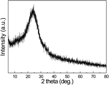
As reactive templates, the morphologies of MnO2 play a significant role in shaping the PPy nanostructures. Fig. 1(a) shows the scan electron microscopy (SEM) image of pristine α-MnO2 nanotubes, in which the open ends of the straight nanotubes can be clearly observed. The corresponding transmission electron microscopy (TEM) image in Fig. 1(b) shows a representative nanotubular structure with an outer diameter of ca. 80 nm and a wall thickness of ca.20 nm. The external and internal surfaces of the nanotubes are very smooth. Fig. 1(c) shows the morphology of the resultant PPy nanostructures. It is observed the PPy nanostructures replicate the 1D shape of MnO2 templates. The diameter of 1D PPy nanostructures is ca. 110 nm and the length is more than 3 μm. The TEM image (Fig. 1(d)) shows the nanotubular structure with a smooth inside and rugged outside as well as a uniform tube wall thickness of ca. 30 nm. The diffusive ring of the selected area electron diffraction pattern (SAED, Fig. 1(d) inset) indicates the amorphous structure of PPy nanotubes. The molecular structure is also confirmed by XRD result, as shown in Fig. 2. A characteristic peak of PPy is centered around 24.6°, which can be assigned to the repeat unit of pyrrole ring, implying the polymer chain is highly oriented. The broad feature of the peak reveals the amorphous nature. These results are also consistent with the PPy materials obtained from conventional chemical or electrochemical methods.10
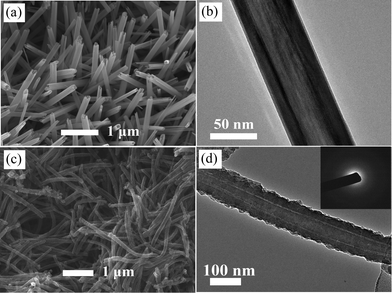 | ||
| Fig. 1 SEM images of (a) α-MnO2 nanotubes and (c) PPy nanotubes; TEM images of (b) α-MnO2 nanotubes and (d) PPy nanotubes. Inset is the SAED pattern of PPy. | ||
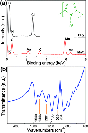
The elemental composition of the PPy nanotubes was analyzed by energy-disperse X-ray spectrum (EDX). As shown in Fig. 3(a), the EDX spectrum of PPy shows the presence of C (70.8%), N (19.5%) and Cl (9.7%). The C/N ratio is consistent with the basic unit of a pyrrole ring. The presence of Cl indicates the resultant PPy is doped by Cl, as schematically illustrated in the inset of Fig. 3(a). There is no signal of elemental Mn in the samples, revealing the MnO2 has been totally converted into soluble Mn2+. The chemical structure of PPy nanotubes is confirmed by FT-IR analysis. The FT-IR spectrum (Fig. 3(b)) shows a C–C stretching band at 1540 cm−1, a conjugated C–N stretching band at 1446 cm−1, a = C–H in-plane deformation band at 1301 cm−1, a N–H in-plane deformation band at 1039 cm−1 and two doping-induced bands at 1165 cm−1 and 964 cm−1 corresponding to C–N stretching vibration and C–H out-of-plane vibration, respectively.15,16 In addition, the high ratio of the integrated peaks of 1540 cm−1 against 1446 cm−1 represents a long π-conjugation length of the PPy backbone. The conjugation length means the length of the polyene segment along which the delocalization of the π-electron takes place, that is to say, the electrical conductivity of PPy nanotubes increases with the conjugation length.10,17 The conductivity of the compressed PPy nanotubes pellet at room temperature is measured to be 13.5 S cm−1 using a standard four-probe method, in sharp contrast to 1.25 S cm−1 for PPy granules (Fig. S2, ESI†).18
The formation mechanism of PPy nanotubes can be rationalized as follows. It is noted that the chemical oxidation potential of MnO2 (Ψ(MnO2/Mn2+)) reaches 1.23 V,19,20 which is strong enough to permit the pyrrole monomers polymerized on the surface of MnO2 template because the chemical oxidation potential of pyrrole monomers is no more than 0.7 V.4 As the redox reaction proceeds, the rigid templates are sacrificed while the pyrrole monomers are polymerized surround the templates, which leads to the formation of PPy nanotubes. The resultant PPy nanotubes are found to have a larger outer diameter than that of MnO2 templates, indicating a preferentially outward growth of PPy through a diffusion-controlled procedure. On the other hand, the larger diameter of PPy can be ascribed to the volume-expansion during the conversion of PPy from MnO2 since the density of PPy is much lower than that of MnO2. In our synthesis, MnO2 by itself can not react with pyrrole monomers in the absence of HCl and an addition of HCl would initiate instant reaction. This suggests hydrogen ions play an essential role in the redox reaction, which is supported by the use of other inorganic or organic acids instead of HCl. When the reaction is finished, the final solution is the characteristic pink color of Mn2+. In view of the insolubility of the MnO2 powders in diluted HCl (0.1 M), the solid MnO2 is confirmed to be reduced to soluble Mn2+ by pyrrole monomers. Based on the above analysis, the formation of PPy nanotubes is schematic illustrated in Fig. 4(a). Firstly, the liquid pyrrole monomers are adsorbed on exterior surface of solid MnO2 nanotube to form a solid–liquid interface. Then the redox reaction between MnO2 and pyrrole monomers takes place at the interface under the assistance of hydrogen ions, which results in the formation of PPy layer/oligomer and an instantaneous dissolution of MnO2. The interfacial polymerization of PPy continues to carry out until the complete removal of MnO2 and the nanotubular PPy is finally obtained. Besides the low-dimensional nanostructures, we believe this reactive template method is general to prepare 3D hierarchical architecture of PPy nanostructures. Two kinds of nano/micro hierarchical structures, i.e. α-MnO2 nanorods-assembled urchin-shape microspheres and δ-MnO2 nanosheets-assembled flower-like microspheres (Fig. S1, ESI†), were used to prepare 3D hierarchical PPy nano/micro structures. Fig. 4(b) shows the urchin-shape PPy microspheres, which is constructed from straight and radially arranged PPy nanotubes. Fig. 4(c) shows the flower-like PPy microspheres consisted of interweaved PPy nanosheets. These hierarchical PPy structures are totally inherited from the MnO2 templates, indicating the reactive template synthesis is effective to prepare PPy complex architecture. In contrast to the hard/soft-template-guided methods of most studies that require additional template removal or the use of organic surfactants, this methodology can be considered to be an eco-friendly and one-step technique.
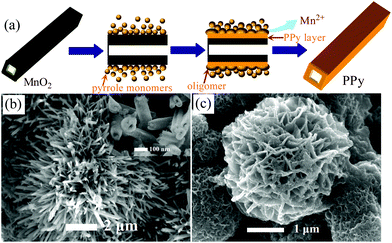 | ||
| Fig. 4 (a) Schematic illustration of the formation mechanism of PPy nanotubes; SEM images of 3D hierarchical PPy architecture consisting of (b) nanotubes and (c) nanosheets. | ||
The as-prepared PPy nanotubes are examined as electrode materials for supercapacitors to explore their potential applications. Fig. 5(a) shows the resulting cyclic voltammetry curves (CVs) of PPy nanotubes at various scan rates. The rectangular and symmetric profiles of these CVs are indications of an ideal pseudocapacitive nature of PPy in KCl electrolyte. It is noted the PPy nanotubes have higher leveled current density than those of PPy granules (Fig. S3, ESI†) at each same scan rate, indicating a much larger specific capacitance of PPy nanotubes. The galvanostatic charging–discharging plots of PPy nanotubes and PPy granules at different applied current densities are present in Fig. 5(b) and (c), respectively. The triangular symmetry and linear slopes again confirm the good pseudocapacitive behavior. The specific capacitance (C) is obtained from discharging curves by using the following eqn (1):
| C = IΔt/mΔU | (1) |
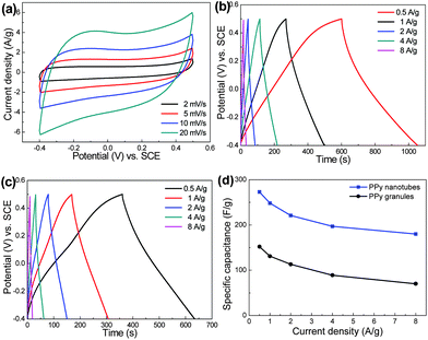 | ||
| Fig. 5 (a) CV curves of PPy nanotubes; galvanostatic charging–discharging plots of (b) PPy nanotubes and (c) PPy granules; (d) specific capacitance as a function of current density. | ||
Here, I is current density (A g−1), Δt is the discharging time (s), m is the mass of active materials (g) and ΔU is the potential window (V). The specific capacitance of PPy nanotubes at 0.5 A g−1 is calculated to be 273 F g−1, which is about twice higher than that of bulk PPy granules (152 F g−1). Although the specific capacitance still falls behand the theoretical value (620 F g−1),21 it is superior or at least comparable to most previous reports, such as 172–197 F g−1 for PPy nanotubes synthesized using methyl orange (MO)/FeCl3,22,23 305 F g−1 for PPy nanowires prepared using cetyltrimethylammonium bromide (CATB)24 and 142 F g−1 for PPy particles.17Fig. 5(d) illustrates a decreasing specific capacitance at an increasing current density. The charge storage mechanism is based on the fast and reversible doping/undoping of PPy and can be written as:24,25
| [PPy+]Cl− + e− ↔ [PPy0] + Cl− | (2) |
Hence, the reduced capacitance at higher current density is ascribed to the limited diffusion time of electrolyte ions into the interior surfaces of PPy. Still, the specific capacitance of PPy nanotubes delivers 180 F g−1 at a high current density of 8 A g−1, whereas that of PPy particles drops quickly to 70 F g−1. The enhanced electrochemical properties of PPy nanotubes can be attributed to (i) the unique 1D nanostructure, which provide short solid-state pathways for ion diffusion, (ii) the rich nanotubular channels for the effective transport of electrolyte during rapid charging–discharging process and (iii) the pronounced electrical conductivity for fast charge transfer from the reversible Faradiac reaction (2).
Conclusions
In summary, we have demonstrated an eco-friendly and one-step approach for chemical synthesis of hierarchical conducting PPy nanostructures via a reactive template of MnO2 in acidic solution. This method allows the shape-controlled synthesis of complex PPy nanostructures, including nanotubes, urchin-shape or flower-like microspheres and also other envisioned architectures inherited from the morphologies of MnO2 templates. The unique 1D nanotubular structure endows the PPy nanotubes with good electrical conductivity and favorable electrochemical properties. We would expect these nanostructured conducting polymers could open new opportunities in a myriad of other applications, such as gas sensors, field effect transistors and electrochromics, etc.Acknowledgements
The authors would like to acknowledge the financial support from research programme for new teacher (13GH0322) and the National Natural Science Foundation of China (No. 51232005).Notes and references
- H. D. Tran, D. Li and R. B. Kaner, Adv. Mater., 2009, 21, 14187 Search PubMed.
- L. Zhang and M. Wan, Adv. Funct. Mater., 2003, 13, 815 CrossRef CAS.
- H. Shirakawa, Angew. Chem., Int. Ed., 2001, 40, 2575 CrossRef CAS.
- S. I. Cho and S. B. Lee, Acc. Chem. Res., 2008, 41, 699 CrossRef CAS PubMed.
- A. N. Aleshin, Adv. Mater., 2006, 18, 17 CrossRef CAS.
- F. Yan, G. Xue and F. J. Wan, Mater. Chem., 2002, 12, 2606 RSC.
- X. Zhang and S. K. Manohar, J. Am. Chem. Soc., 2005, 127, 14156 CrossRef CAS PubMed.
- Y. K. Koo, B. H. Kim, D. H. Park and J. Joo, Mol. Cryst. Liq. Cryst., 2004, 425, 55 CrossRef CAS.
- F. L. Cheng, M. L. Zhang and H. Wang, Sensors, 2005, 5, 245 CrossRef CAS.
- J. Jang and H. Yoon, Langmuir, 2005, 21, 11484 CrossRef CAS PubMed.
- J. Jang and H. Yoon, Chem. Commun., 2003, 720 RSC.
- X. Yang, T. Dai, Z. Zhu and Y. Lu, Macromol. Rapid Commun., 2005, 1736 CrossRef CAS.
- X. Yang, Z. Zhu, T. Dai and Y. Lu, Polymer, 2007, 48, 4021 CrossRef CAS PubMed.
- T. Dai, X. Yang and Y. Lu, Nanotechnology, 2006, 17, 3028 CrossRef CAS.
- L. Pan, L. Pu, Y. Shi, S. Song, Z. Xu, R. Zhang and Y. Zheng, Adv. Mater., 2007, 19, 461 CrossRef CAS.
- H. S. Kim, D. H. Park, Y. B. Lee, D. C. Kim, H. J. Kim and J. Joo, Synth. Met., 2007, 157, 910 CrossRef CAS PubMed.
- J. Li, L. Cui and X. Zhang, Appl. Surf. Sci., 2010, 256, 4339 CrossRef CAS PubMed.
- Y. Yang, J. Liu and M. Wan, Nanotechnology, 2002, 13, 771 CrossRef CAS.
- K. A. Noh, D. W. Kim, C. S. Jin, K. H. Shin, J. H. Kim and J. M. Jo, J. Power Sources, 2003, 124, 593 CrossRef CAS.
- X. Wang and Y. Li, J. Am. Chem. Soc., 2002, 124, 2880 CrossRef CAS PubMed.
- G. A. Snook, P. Kao and A. S. Best, J. Power Sources, 2011, 196, 1 CrossRef CAS PubMed.
- J. H. Liu, J. W. An, Y. X. Ma, M. L. Li, R. B. Ma, M. Yu and S. M. Li, Eur. Phys. J.: Appl. Phys., 2012, 57, 30702 CrossRef.
- H. Mi, X. Zhang, X. Ye and S. Yang, J. Power Sources, 2008, 176, 403 CrossRef CAS PubMed.
- Q. F. Wu, K. X. He, H. Y. Mi and X. G. Zhang, Mater. Chem. Phys., 2007, 101, 367 CrossRef CAS PubMed.
- J. H. Park, J. M. Ko, O. O. Park and D. W. Kim, J. Power Sources, 2002, 105, 20 CrossRef CAS.
Footnote |
| † Electronic supplementary information (ESI) available: Experimental details for the synthesis of MnO2 nanostructures. SEM images of MnO2 nanostructure and granular PPy. CV and charging–discharging curves of PPy granules. See DOI: 10.1039/c3ra45824e |
| This journal is © The Royal Society of Chemistry 2014 |

