An environmentally friendly and economic membrane based on cellulose as a gel polymer electrolyte for lithium ion batteries
Shiying
Xiao
,
Faxing
Wang
,
Yaqiong
Yang
,
Zheng
Chang
and
Yuping
Wu
*
New Energy and Materials Laboratory (NEML), Department of Chemistry & Shanghai Key Laboratory of Molecular Catalysis and Innovative Materials, Fudan University, Shanghai 200433, China. E-mail: wuyp@fudan.edu.cn; Fax: +86-21-55664223
First published on 7th November 2013
Abstract
A green and environmentally friendly polymer, methyl cellulose (MC), is used as a host matrix of a gel polymer electrolyte for lithium ion batteries. It shows good mechanical performance and thermal stability. The ionic conductivity of the gel polymer electrolyte is 0.20 mS cm−1 and it has a higher lithium ion transference number (t+ = 0.29) than the commercial separator (0.27). When evaluated using LiFePO4 as cathode and Li metal as the counter and reference electrode, the LiFePO4 cathode exhibits relatively higher reversible capacity for the gel polymer electrolyte than that for the commercial separator. In addition, the rate capability and cycling performance are also comparable with those for the commercial separator. This provides another direction for gel polymer electrolytes and environmental protection.
1. Introduction
Nowadays, lithium ion batteries (LIBs), which have become one of the most important energy storage technologies, play a crucial role in the modern world and have become an indispensible part of our daily life. They were invented in the early 1990s, and now are widely used as power sources for electronic devices such as laptops, cell-phones and electric power tools.1–5 Although lithium ion batteries are considered to be the most successful electrochemical devices with high energy density, they are still associated with the risk of safety accidents because of the flammability of the organic electrolytes which are widely used in the conventional lithium ion batteries.6–9 It is acknowledged that this problem can be solved by using the polymer electrolyte (PE) as the separator and electrolyte for lithium ion batteries.10–14 The use of PEs makes lithium ion batteries safer, lighter, and more flexible in shape. Early research in PEs emphasized on solid polymer electrolytes based on polyethers, beginning with Wright's research about complexes of PEO and sodium salts.15,16 Despite extensive researches on lithium polyether-based conductors, the ionic conductivity of the solid polymer electrolytes is insufficient for practical applications.17,18 Then, the gel-type polymer electrolytes (GPEs), which are made by absorbing liquid electrolyte into the polymer matrix and have the characteristics of both solid and liquid electrolytes, have got increasing attention for their good ionic conductivity, wide electrochemical window, good compatibility with the electrodes and good thermal stability.19–24 However, the environmental effects should be considerated since the separators used for lithium ion batteries could not be recycled. So far, the well-studied polymer hosts are based on poly(vinylidene difluoride) (PVDF) and its copolymers, and modified polyethylene and polypropylene, which are not friendly to the environment.16,20 So far there is no consideration on the biocompatibility and biodegradation of polymer electrolytes and separators.Since 1960s, when the first commercial membrane was invented via phase inversion method, significant milestones in the development of membrane technologies have been achieved.25 Cellulose, the most abundant renewable resource on earth, will become the main chemical resource in the future since it is biocompatible and biodegradable.26 Moreover, numerous new functional materials from cellulose are being developed over a broad range of applications, because of the increasing demand for environmentally friendly and biocompatible products.27,28 Methyl cellulose (MC) is a water-soluble polysaccharide derivative that is widely used as a binder or thickener in pharmaceuticals, foods and ceramics.29
In this paper, we found that a membrane based on biocompatible MC, for the first time, can be used for lithium ion batteries as a host for gel polymer electrolytes. In addition, its electrochemical performance when evaluated by using LiFePO4 as the cathode is mostly superior to that for the commercial separator. It is anticipated that this gel polymer electrolyte will open a chance for a sharp decrease of cost for lithium ion batteries and provide a new direction for research and industry.
2. Experimental
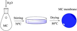
The preparation of the polymer matrix membrane is simple, which is schematically shown in Scheme 1. In detail, methyl cellulose (MC) (Aladdin, CAS 9004-67-5, –OCH3: 25–30%, 100 mg) was dissolved in distilled water (40 mL) at room temperature with constant stirring, and then the MC solution was casted on a glass plate. After the solvent water was vaporized at 80 °C, a thin MC membrane with the thickness of 20 μm was obtained. The membrane was punched into circular pieces (d = 19 mm). After drying under vacuum at 80 °C for 24 h, the pieces were soaked in the organic electrolyte 1 mol L−1 LiPF6 solution in EC/DMC/EMC (ethylene carbonate/dimethyl carbonate/ethyl methyl carbonate, 1/1/1, w/w/w, Zhangjiagang Guotai-Huarong New Chemical Materials Co., Ltd) over 12 h in a glove box to obtain the gel membranes or GPEs for further measurement.The surface morphology of the prepared membranes was examined by means of scanning electron microscope (SEM, Philip XL30). The specimens for the SEM micrographs of the cross-section of the membranes were prepared by fracturing them in liquid nitrogen. FT-IR measurement was carried out on a BRUKER VECTOR-22 spectrometer. Thermogravimetric analysis (TGA) and differential scanning calorimetry (DSC) of the membranes were carried out by utilizing a Perkin-Elmer TGA7/DSC7. The thickness of the membranes was measured with a micrometer (SM & CTW, Shanghai). Stress–strain tests were conducted by using a Sansi YG832 tensile testing machine with a crosshead speed of 1 mm min−1. The calculation of the amount of liquid electrolyte uptake (η) is based to the eqn (1):
| η = (Wt − Wo)/Wo × 100% | (1) |
The ionic conductivities were measured in the temperature range 298–348 K by using an electrochemical working station CHI660C (Chenhua) in the frequency range of 10 Hz to 100 kHz. The membranes were sandwiched between two stainless steel electrodes of 2.54 cm2 in area for ionic conductivity measurement. In order to calculate the lithium ion transference number of the membranes, the model cell was assembled by using Li metal as both electrodes. The electrochemical window of the gel polymer electrolytes was determined from the linear sweep voltammogram which was carried out by the electrochemical working station using a two-electrode cell. Stainless steel was used as the working electrode and lithium foil as the counter and reference electrode. The measurement was done between 0 V and 6 V (vs. Li+/Li) at the scan rate of 1 mV s−1.
Electrochemical performance of the membranes was evaluated by coin-type cells, where lithium foil was used as the counter and reference electrode, and the mixture of LiFePO4 (E60, China), acetylene black and PVDF in the weight ratio of 8![[thin space (1/6-em)]](https://www.rsc.org/images/entities/char_2009.gif) :
:![[thin space (1/6-em)]](https://www.rsc.org/images/entities/char_2009.gif) 1
1![[thin space (1/6-em)]](https://www.rsc.org/images/entities/char_2009.gif) :
:![[thin space (1/6-em)]](https://www.rsc.org/images/entities/char_2009.gif) 1 as the working electrode. The membranes were immersed in the organic electrolyte for 12 h, then used as the separators and electrolytes. The cyclic voltammograms (CVs) of the cells were measured at the scan rate of 0.1 mV s−1. The rate behavior of the LiFePO4 cathodes using different electrolytes were tested at the rate of 0.1 C, 0.2 C, 0.5 C, 1 C and then 0.2 C with five cycles for each rate, and the cycling performance of the LiFePO4 cathodes was carried out by a land battery tester at the current density of 0.2 C between 2.5 and 4.2 V.
1 as the working electrode. The membranes were immersed in the organic electrolyte for 12 h, then used as the separators and electrolytes. The cyclic voltammograms (CVs) of the cells were measured at the scan rate of 0.1 mV s−1. The rate behavior of the LiFePO4 cathodes using different electrolytes were tested at the rate of 0.1 C, 0.2 C, 0.5 C, 1 C and then 0.2 C with five cycles for each rate, and the cycling performance of the LiFePO4 cathodes was carried out by a land battery tester at the current density of 0.2 C between 2.5 and 4.2 V.
3. Results and discussion
The SEM micrographs of the surface and cross section of the prepared MC membrane were shown in Fig. 1a and b. The prepared membrane presents smooth surface and a solid cross section. No obvious porous structure can be seen from the surface or the cross section of the MC membrane. The thickness of the membrane is about 20 μm as we targeted. The IR spectra of the MC membrane was shown in Fig. 1c. The characteristic absorption peak of MC are observed at 3000–2800 cm−1 (C–H stretching in CH2 and CH3), 1646 cm−1 (C–C ring stretching), 1458 cm−1 (C–H bending in, CH2), 1300–1000 cm−1 (C–O stretching).30 Since the methylation is not 100%, there are still some remained –OH groups, which are at 3446 cm−1 as a large absorption peak. According to the strain–stress curves in Fig. 1d, the tensile strength of the Celgard 2730 was nearly 40 MPa, while that of MC membrane was only 20 MPa. Although it is lower than the commercial membrane Celgard 2730, it is high enough to be used for lithium ion batteries.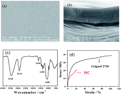 | ||
| Fig. 1 SEM micrographs of (a) the surface and (b) cross section of MC membrane, (c) IR spectra of MC, and (d) stress–strain curves of MC membrane and Celgard 2730. | ||
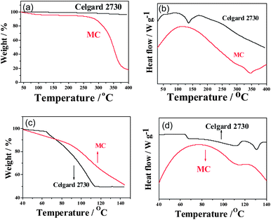
Fig. 2a shows the thermogravimetric (TG) curves of the Celgard 2730 and MC membranes. Both of them can be stable up to 250 °C. In the case of MC, it begins to decompose at 250 °C. Since there are some remaining –OH groups, they are easy to absorb water. As a result, there is a little weight loss before 100 °C. In the case of the Celgard 2730, it is from polyethylene and not easy to decompose below 400 °C, which is one reason why it provides a lot of white pollutions to the environment. From the differential scanning calorimetry (DSC) curves shown in Fig. 2b, it is clear that the MC is very stable and does not present any phase transition until its drastic decomposition at 340 °C, indicating by a large endothermic peak in the DSC curve. The main reason is that the cellulose derivative, MC, is similar mostly to cellulose and does not have a melting point. Before its decomposition, it exists in the state of solid. This suggests that the MC could avoid the direct contact of two electrodes prior to its decomposition. In the case of the Celgard 2730, there is a large endothermal peak at the around of 130 °C, indicating the melt-down of the polymer host, polyethylene. After this peak, it just absorbs heat due to the existence of liquid melt, suggesting that above 130 °C the short circuit of lithium ion batteries could not be stopped by this separator.
The retention ability of electrolytes is very important to the safety of lithium ion batteries. The TG-DSC curves of the gel MC membrane and Celgard 2730 separator soaked with the same amount of the electrolyte (0.6 mL g−1) are shown in Fig. 2c and d. The organic electrolyte in the commercial separator Celgard 2730 starts to evaporate at 65 °C which is indicated by the sharp endothermic peak in the DSC curve, which is similar to the former reports.20,31 This limits the work temperature of lithium ion batteries below 65 °C since after this temperature the pressure in a lithium ion battery will increase and lead to destruction and possible explosion of lithium ion battery. When the temperature arrives at 112 °C, all the liquid electrolyte is evaporated, indicated by no weight loss in the TG curve and the end of endothermal peak in the DSC curve. In terms of the gel MC membrane, it does not appear clear sharp weight loss until 80 °C where an endothermal peak begins in the DSC curve. This suggests that the liquid electrolyte is absorbed by the MC host. Due to a large mount of –OH groups, the absorption interaction is not weak. In addition, the evaporation rate of the liquid electrolyte in the MC is much slower than that for the commercial separator with the same amount of electrolyte. Only when the temperature arrives above 140 °C, is the organic liquid electrolyte evaporated completely. The marked evaporation of the liquid electrolyte is at about 110 °C, indicating by the endothermal peak in the DSC curve.
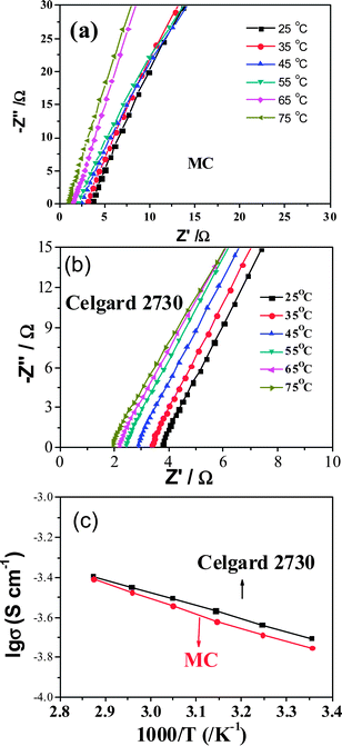
The uptake amount of the membrane is one of the main factors for ionic conductivity. The uptake amount of the MC membrane can be up to 73.4 wt% which is a little lower than that of Celgard 2730 (90.9 wt%). The main reason is that the former is not porous and the latter is porous. The ionic conductivity for the membranes saturated with the liquid electrolyte was calculated from the impedance plots shown in Fig. 3a and b, and the dependence of their ionic conductivity on temperature is shown in Fig. 3c. The ionic conductivity increases with temperature and the plots of log![[thin space (1/6-em)]](https://www.rsc.org/images/entities/char_2009.gif) σ versus T−1 are linear, which is the typical Arrhenius behavior for most polymer electrolytes.32 The activation energies for the movement of ions are 13.48 and 11.93 kJ mol−1, respectively, for the MC and commercial Celgard separator. In the MC, there are quite some polaric groups and the MC membrane is solid, the movement of ions needs more activation energy. In the Celgard separator, there is no evident interaction of the electrolyte with the polymer host and the activation energy for the movement of ions is similar to that of liquid electrolyte. Though the detailed mechanism for the MC membrane is not clear now, it indicates that the polymer host really affects the movement of ions, suggesting a good direction to further improve the ionic conductivity in the gel polymer electrolytes. The total ionic conductivity of the gel MC membrane was 0.20 mS cm−1 at 25 °C, a little lower than that of the commercial separator Celgard 2730 (0.21 mS cm−1). One reason is that the absorbed amount of the liquid electrolyte is less. Another reason is similar to the calculated activation energy.
σ versus T−1 are linear, which is the typical Arrhenius behavior for most polymer electrolytes.32 The activation energies for the movement of ions are 13.48 and 11.93 kJ mol−1, respectively, for the MC and commercial Celgard separator. In the MC, there are quite some polaric groups and the MC membrane is solid, the movement of ions needs more activation energy. In the Celgard separator, there is no evident interaction of the electrolyte with the polymer host and the activation energy for the movement of ions is similar to that of liquid electrolyte. Though the detailed mechanism for the MC membrane is not clear now, it indicates that the polymer host really affects the movement of ions, suggesting a good direction to further improve the ionic conductivity in the gel polymer electrolytes. The total ionic conductivity of the gel MC membrane was 0.20 mS cm−1 at 25 °C, a little lower than that of the commercial separator Celgard 2730 (0.21 mS cm−1). One reason is that the absorbed amount of the liquid electrolyte is less. Another reason is similar to the calculated activation energy.
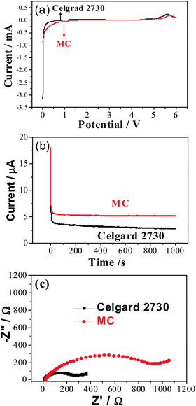
A linear sweep voltammetry experiment performed in the potential range of 0–6.0 V (vs. Li+/Li) at the scan rate of 1 mV s−1 is shown in Fig. 4a. The current flow is very small when the voltage is below 4.8 V (vs. Li+/Li), which makes them very suitable for the application in lithium ion batteries. The lithium ion transference number, t+, is an important parameter for lithium ion batteries.33 In Fig. 4b, it is clear that the lithium ion transfer number in the MC membrane saturated with the liquid electrolyte is 0.29, which is a little higher than that of the commercial separator Celgard 2730 (t+ = 0.27). The main difference is that there is an interaction between the –OH groups in the MC host and the organic electrolyte and lithium salt. As a result, the ionic conductivity for lithium ions are 0.058 and 0.0567 mS cm−1, respectively, in the gel MC membrane and the commercial separator saturated with liquid electrolyte.
The impedance spectra in Fig. 4c shows that electrode delivers a semicircle at high frequency and a linear region at low frequency. The semicircles correspond to a parallel combination of charge-transfer resistance (Rct) and double-layer capacitance. The Rct values can be estimated from the diameter of the semicircle on the real axis, which imply, that the MC exhibits higher interfacial resistance compared to the commercial membrane. This is mainly due to the low degree of methylation and some active hydroxyl groups will take part in reactions with lithium, which result in big interfacial resistance during the whole charge and discharge process.
The electrochemical performance of the gel MC membranes and Celgard 2730 was evaluated by using LiFePO4 as the cathode and Li metal as the counter and reference electrode. From the cyclic voltammograms (CVs) (Fig. 5a), it can be seen that for the LiFePO4 cathode using Celgard 2730 as the separator, the oxidation and reduction peaks appear at around 3.6 and 3.1 V (vs. Li+/Li), respectively. The potential interval between two peaks is 0.5 V. However, in the case of the LiFePO4 cathode using the gel MC membrane, the oxidation and reduction peaks appear at around 3.8 and 3.0 V (vs. Li+/Li), respectively. The potential difference of redox peaks is 0.8 V, larger than that of Celgard 2730, which is consistent with the larger impedance of the cell with MC as the separator. The main reason is just as mentioned above that the methylation percent is not high, about 25–30%. The left hydroxyl groups in the MC is not favorable to the contact with lithium metal, which leads to larger interphase resistance. As to its contact with the cathode, it does not present much side effects at relatively lower discharge rate since the cathode materials present excellent electrochemical performance even in aqueous electrolytes.34–37 The corresponding charge–discharge curves for the LiFePO4 cathodes tested at the rate of 0.2 C (Fig. 5b) show that the difference between charge and discharge curves for the Celgard separator is small, about 0.2 V, similar to the former reports.38,39 In the case of the gel MC membrane, the voltage profiles of LiFePO4 are also flat. However, the difference between charge and discharge voltages is a little larger. This higher voltage difference is not due to the different ionic conductivity.40,41 Instead, it can be ascribed to the difference in the interphase resistance. This is consistent with the larger peak separation from CV and the larger interphase resistance suggested from Fig. 4c. The reversible capacity of the LiFePO4 for the gel MC membrane is about 130 mA h g−1 at 0.2 C, which is a little higher than that for the commercial separator, about 126 mA h g−1 (Fig. 5c). This is mainly due to the little higher lithium ion transference number and the higher Li+ ionic conductivity in the MC gel polymer electrolyte than those in the Celgard 2730. At different current densities such as 0.1 C, 0.2 C, 0.5 C and 1 C, it still keeps higher discharge capacities than those for the commercial separator saturated with the liquid electrolyte. When tested at the charge and discharge rate of 1 C, the LiFePO4 still presents a discharge capacity of 60 mA h g−1. The cycling performance of LiFePO4 between 2.5 and 4.2 V (vs. Li+/Li) using the GPE at 0.2 C (34 mA g−1) is very good, similar to that of the commercial separator (Fig. 5d). After 40 cycles at 0.2 C there is still no evident capacity fading.
Our above results show that the ionic conductivity of lithium ions in the gel MC membrane is a little larger than that in the commercial separator saturated with the liquid electrolyte. As a result, a higher reversible capacity for the LiFePO4 and a little better rate capability are achieved. In the case of the overpotential during charge and discharge process, it is mainly dependent on the interphase resistance in our case though it is well known that the transportation of lithium ion is important. However, this interphase does not prevent the movement of lithium ions. Instead, it mainly prevents the further direct interaction between the Li metal and the MC polymer host. As a result, it does not affect the rate capability.
This demonstrates that the MC membrane can be used in lithium ion batteries and leads to a higher discharge capacity for the cathode material compared with the commercial separator though with a little higher overpotential. Its low cost, simple manufacture process, biocompatibility and biodegradation make MC be of great attractions to the lithium ion batteries.
4. Conclusions
An environmentally friendly polymer material, methyl cellulose (MC), was successfully found to be useful in lithium ion batteries as a host for a gel polymer electrolyte. It shows good mechanical performance and excellent thermal stability which makes lithium ion batteries much safer. Besides, the ionic conductivity of lithium ions in the gel MC membrane is a little higher than that of the commercial separator Celgard 2730 saturated with liquid electrolyte. When evaluated using LiFePO4 as the cathode and Li metal as the counter and reference electrode, the gel MC membrane leads to a higher discharge capacity at room temperature in comparison with the commercial separator. The rate capacity and cycling performance are also very good. This shows that this MC membrane has great attraction to lithium ion batteries due to its benignment to environment, independent of non-renewable oil industry and low cost.Acknowledgements
Financial supports from International Science & Technology Cooperation Program of China (2010DFA61770), NSFC (21374021) and STCSM (12JC1401200) are gratefully appreciated.Notes and references
- P. Simon and Y. Gogotsi, Nat. Mater., 2008, 7, 845 CrossRef CAS PubMed.
- Y. P. Wu, X. B. Dai, J. Q. Ma and Y. J. Cheng, Lithium Ion Batteries: Practice and Applications, Chemical Industry Press, Beijing, 2004 Search PubMed.
- X. Zuo, X. M. Liu, F. Cai, H. Yang, X. D. Shen and G. Liu, J. Mater. Chem., 2012, 22, 22265 RSC.
- J. M. Tarascon and M. Armand, Nature, 2001, 414, 359 CrossRef CAS PubMed.
- F. X. Wang, S. Y. Xiao, Y. Shi, L. L. Liu, Y. S. Zhu, Y. P. Wu and R. Holze, Electrochim. Acta, 2013, 93, 301 CrossRef CAS.
- H. Y. Zou, E. Gratz, D. Apelian and Y. Wang, Green Chem., 2013, 15, 1183 RSC.
- H. P. Zhao, C. Y. Jiang, X. M. He, J. G. Ren and C. R. Wan, J. Membr. Sci., 2008, 310, 1 CrossRef CAS.
- Y. S. Zhu, X. W. Gao, X. J. Wang, Y. Y. Hou, L. L. Liu and Y. P. Wu, Electrochem. Commun., 2012, 22, 29 CrossRef CAS.
- L. G. Lu, X. B. Han, J. Q. Li and J. F. Hua, J. Power Sources, 2013, 226, 212 CrossRef.
- A. S. Aricò, P. Bruce, B. Scrosati, J.-M. Tarascon and W. V. Schalkwijk, Nat. Mater., 2005, 4, 366 CrossRef PubMed.
- J. Y. Song, C. L. Cheng, Y. Y. Wang and C. C. Wan, J. Electrochem. Soc., 2002, 149, A1230 CrossRef CAS.
- Q. Z. Xiao, X. Z. Wang, W. Li, Z. H. Li, T. J. Zhang and H. L. Zhang, J. Membr. Sci., 2009, 334, 117 CrossRef CAS.
- H. P. Zhang, P. Zhang, Z. H. Li, M. Sun, Y. P. Wu and H. Q. Wu, Electrochem. Commun., 2007, 9, 1700 CrossRef CAS.
- (a) Z. X. Yu, D. Qin, Y. D. Zhang, H. C. Sun, Y. H. Luo and Q. B. Meng, Energy Environ. Sci., 2011, 4, 1298 RSC; (b) Y. S. Zhu, F. X. Wang, L. L. Liu, S. Y. Xiao, Y. Q. Yang and Y. P. Wu, Sci. Rep., 2013, 3, 3187 Search PubMed.
- Y. G. Andrew and P. G. Bruce, Electrochim. Acta, 2000, 45, 1417 CrossRef.
- Y. G. Sun, Nano Energy, 2013, 2, 811 Search PubMed.
- C. G. Wu, M. I. Lu and H. J. Chuang, Polymer, 2005, 46, 5929 CrossRef CAS.
- A. Asghar, Y. A. Samad and B. S. Lalia, J. Membr. Sci., 2012, 421, 85 CrossRef.
- A. M. Christie, S. J. Lilley, E. Staunton, Y. G. Andreev and P. Bruce, Nat. Mater., 2005, 4, 366 CrossRef PubMed.
- P. Zhang, L. L. Li, D. N. He, Y. P. Wu and T. Shimizu, Acta Polym. Sin., 2011, 2, 107 Search PubMed.
- P. Raghavan, X. Zhao, J. Manuel, G. S. Chauhan, J. H. Ahn, H. S. Ryu, H. J. Ahn and K. W. Kim, Electrochim. Acta, 2010, 55, 1347 CrossRef CAS.
- S. T. Chen, X. Li, K. Yao, F. E. H. Tay, A. Kumar and K. Y. Zeng, Polymer, 2012, 53, 1404 CrossRef CAS.
- J. W. Fergus, J. Power Sources, 2010, 195, 4554 CrossRef CAS.
- P. Carol, P. Ramakrishnan, B. John and G. Cheruvally, J. Power Sources, 2011, 196, 10156 CrossRef CAS.
- F. Liu, N. A. Hashim and Y. Liu, J. Membr. Sci., 2011, 375, 1 CrossRef CAS.
- S. J. Eichhorn, R. J. Young and G. R. Davies, Biomacromolecules, 2005, 6, 507 CrossRef CAS PubMed.
- D. Klemm, B. Heublein, H. Fink and A. Bohn, Angew. Chem., Int. Ed., 2005, 44, 3358 CrossRef CAS PubMed.
- N. Shi, Q. Y. Liu, Q. Zhang, T. J. Wang and L. L. Ma, Green Chem., 2013, 15, 1967 RSC.
- Y. F. Tang, X. Y. Wang, Y. Li and M. Lei, Carbohydr. Polym., 2010, 82, 833 CrossRef CAS.
- T. Funami and Y. Kataoka, Food Hydrocolloids, 2007, 21, 46 CrossRef CAS.
- Y. S. Zhu, S. Y. Xiao, Y. Shi, Y. Q. Yang and Y. P. Wu, J. Mater. Chem. A, 2013, 1, 7790 CAS.
- Z. H. Li, C. Cheng, X. Y. Zhan, Y. P. Wu and X. D. Zhou, Electrochim. Acta, 2009, 54, 4403 CrossRef CAS.
- D. Saikia, H. Y. Wu, Y. C. Pan, C. P. Lin and K. P. Huang, J. Power Sources, 2011, 196, 2826 CrossRef CAS.
- R. Ruffo, C. Wessells, R. A. Huggins and Y. Cui, Electrochem. Commun., 2009, 11, 247 CrossRef CAS.
- W. Tang, L. L. Liu, Y. S. Zhu, H. Sun, Y. P. Wu and K. Zhu, Energy Environ. Sci., 2013, 5, 6909 Search PubMed.
- W. Tang, Y. S. Zhu, Y. Y. Hou, L. L. Liu, Y. P. Wu, K. P. Loh, H. P. Zhang and K. Zhu, Energy Environ. Sci., 2013, 6, 2093 CAS.
- W. Tang, Y. Y. Hou, F. X. Wang, L. L. Liu, Y. P. Wu and K. Zhu, Nano Lett., 2013, 13, 2036 CrossRef CAS PubMed.
- F. Y. Cheng, J. Liang, Z. L. Tao and J. Chen, Adv. Mater., 2011, 23, 1695 CrossRef CAS PubMed.
- F. Brochu, A. Guerfi, J. Trottier and K. Zaghib, J. Power Sources, 2012, 214, 1 CrossRef CAS.
- Y. S. Zhu, F. X. Wang, L. L. Liu, S. Y. Xiao and Y. P. Wu, Energy Environ. Sci., 2013, 6, 618 CAS.
- J. Liu, T. E. Conry, X. Y. Song, M. M. Doeff and T. J. Richardson, Energy Environ. Sci., 2011, 4, 885 CAS.
| This journal is © The Royal Society of Chemistry 2014 |

