Facile fabrication of yolk–shell structured porous Si–C microspheres as effective anode materials for Li-ion batteries†
Yachao
Ru
,
David G.
Evans
,
Hong
Zhu
and
Wensheng
Yang
*
State Key Laboratory of Chemical Resource Engineering, Beijing University of Chemical Technology, Beijing 100029, P. R. China. E-mail: yangws@mail.buct.edu.cn; Fax: +86 10 64425385; Tel: +86 10 64435271
First published on 8th November 2013
Abstract
Yolk–shell structured porous Si–C microspheres have been fabricated by magnesiothermic reduction of silica spheres inside carbon shells and exhibit excellent electrochemical performance due to the porous yolk–shell structure.
Silicon (Si) is considered as a promising anode material for rechargeable Li-ion batteries (LIB), owing to its high theoretical specific capacity (about 4200 mA h g−1), high abundance in the earth's crust and its environmentally friendly nature.1 However, the large volume changes (>300%) during the Li+ insertion/extraction process and the low intrinsic electric conductivity of Si lead to severe pulverization and polarization of Si electrodes, causing poor cycling and rate performances, which severely limits their applications.2 Considerable efforts have been made to improve the cyclability and conductivity of Si-based anode materials, such as preparing nanoscale silicon structures,3 porous structures,4 and Si/C composites.5 Recently, a novel class of Si/C composites known as yolk–shell or hollow core–shell microspheres has been shown to have potential applications in LIB. Many researchers have synthesized such yolk–shell structures by coating silicon nanoparticles (SiNPs) as the “yolk” with amorphous carbon as the “shell”.6 The void space cushions the huge volume expansion during Li+ insertion thus preserving the integrity of the electrode framework, and the carbon shells provide the essential transport channels for both electrons and Li+ from/to the inner silicon.6b As a result, these materials show good electrochemical performance.
However the preparation of the required silicon nanoparticles is complicated and involves laser irradiation, chemical vapor deposition (CVD) methods and/or high temperature leading to relatively high costs.7 Furthermore the silicon nanoparticles have a strong tendency to aggregation and oxidation. In contrast, magnesiothermic reduction can be used to produce silicon from readily available silica at relatively low temperature, and has the additional advantages of being a low cost and environmentally benign process.8 In addition, the products obtained by magnesiothermic reduction tend to retain the morphology of the precursor, and are resistant to aggregation of the particles. An increasing number of Si-based materials, including hollow silicon spheres,9 silicon nanotubes10 and porous silicon materials,11 have recently been prepared using this method.
Herein we report a facile way to create a yolk–shell structure which we call mpSi@Void@mpC (where mp denotes mesoporous) by using abundant and cheap silica as the raw material. A carbon shell was first coated on the silica, followed by selective etching of silica to create the space required for expansion of silicon during eventual application in LIB. The carbon shells were designed to be porous thus facilitating diffusion of magnesium through the pore channels and allowing magnesiothermic reduction of the inner silica “yolk”. In comparison with the yolk–shell structures reported previously,6b mpSi@Void@mpC has the advantage that both its core and shell are porous, which should make it much easier for the infiltration of electrolyte—thus shortening the diffusion lengths of Li+—if it is used as an anode material for LIB.
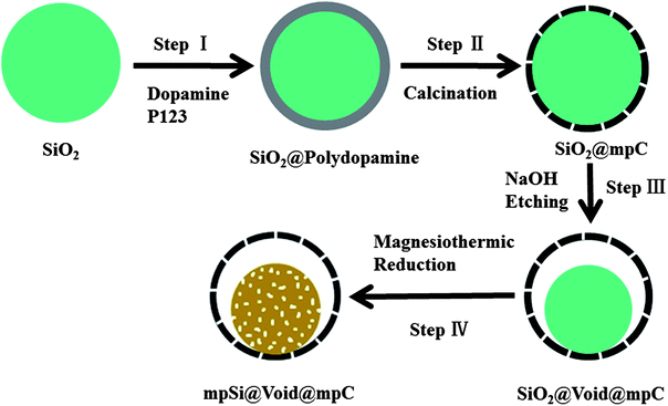
As shown in Fig. 1, the fabrication of mpSi@Void@mpC microspheres is relatively simple. Step I involves the preparation of SiO2@polydopamine using silica spheres (with diameter about 1200 nm, Fig. S1a in the ESI†) as precursor, dopamine as carbon source and triblock copolymer PEO–PPO–PEO (P123) as a pore forming surfactant,12 immediately followed by calcination to form the SiO2@mpC microspheres (Fig. S1b†) in Step II. In Step III, NaOH was used to etch part of the silica to afford SiO2@Void@mpC (Fig. S2†); the size of SiO2 cores and the space between shells and cores can readily be controlled by varying the concentration of NaOH or the etching time. Finally, in Step IV, uniform and monodisperse mpSi@Void@mpC microspheres can be obtained in high yield by in situ magnesiothermic reduction of SiO2 cores inside the hollow carbon spheres, followed by acid etching to remove magnesium oxide and the residual magnesium and SiO2. No hazardous silane gas or complex CVD process is used, and the whole process is easily scalable.
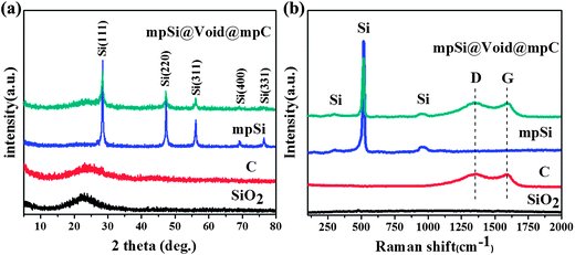
Fig. 2 shows the X-ray diffraction (XRD) patterns and Raman spectra of the SiO2 spheres and the mpSi@Void@mpC particles. For the purposes of comparison, the corresponding data for both hollow carbon spheres (prepared by extending the NaOH etching time (Step III) to completely dissolve the silica core of SiO2@mpC; scanning electron microscopy (SEM) and transmission electron microscopy (TEM) images of this material are shown in Fig. S3†), and mpSi spheres (prepared by direct magnesiothermic reduction of the SiO2 spheres; SEM and TEM images of this material are shown in Fig. S4†) are also illustrated in Fig. 2. The XRD patterns of SiO2 and hollow carbon spheres (Fig. 2a) show a single broad peak respectively centered at about 23° and 24°, which are characteristic of amorphous SiO2 and amorphous carbon. After magnesiothermic reduction, five diffraction peaks appear in the XRD patterns of mpSi spheres and mpSi@Void@mpC particles, which can be indexed to the cubic diamond phase of Si (JCPDS card no. 27–1402). There is also a broad peak at 24° in the pattern of mpSi@Void@mpC, which can be attributed to the presence of the carbon shells. The Raman spectrum of mpSi@Void@mpC (Fig. 1b) shows peaks characteristic of Si at about 300, 518, and 950 cm−1, and peaks at 1350 and 1590 cm−1 which can be respectively assigned to the D and G bands of carbon. The ratios of the D and G bands are comparable to one another for both mpSi@Void@mpC and hollow carbon spheres, suggesting that a disordered carbon structure is present in both cases.
 | ||
| Fig. 2 XRD patterns (a) and Raman spectra (b) of SiO2 spheres, hollow carbon spheres, mpSi spheres and mpSi@Void@mpC spheres. | ||
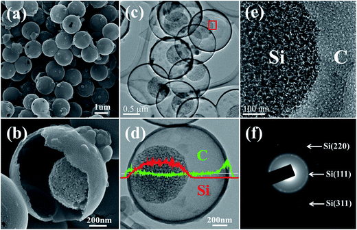
The structure of mpSi@Void@mpC was further investigated by SEM and TEM. The SEM image in Fig. 3a shows that the mpSi@Void@mpC particles are spherical and monodisperse, with an average diameter of approximately 1300 nm. The yolk–shell structure is clearly revealed by a close-up view of a broken particle (Fig. 3b). Further insight into the yolk–shell structure is obtained by TEM images at different magnifications (Fig. 3c–e), which demonstrate that the yolk-like cores are approximately 800 nm in diameter, and completely encapsulated by the hollow carbon spheres. Additionally, Si and C intensity line scans (Fig. 3d) confirm the existence of a hollow interior space between core and shell, which is in accord with a yolk–shell structure. The crystalline nature of the silicon is verified by the selected area electron diffraction (SAED) pattern (Fig. 3f). The TEM image in Fig. 3e shows that both the silicon core and carbon shell are mesoporous materials; the silicon cores are composed of primary silicon crystallites, which are homogeneously distributed. The porous structure of the carbon shell is further confirmed by the nitrogen adsorption/desorption isotherms of the hollow carbon spheres (Fig. S5†), which show a distinct hysteresis loop at high relative pressures and a pore size distribution characteristic of mesoporous materials.
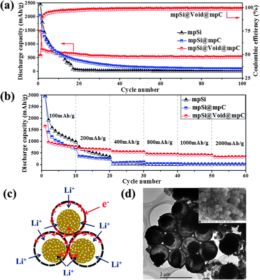
The mpSi@Void@mpC microspheres were tested in LIB to investigate the effects of the yolk–shell structure on the electrochemical performance. The specific capacity values are calculated on the basis of the total weight of mpSi@Void@mpC, in which carbon constitutes ∼56% of the mass (as determined by thermogravimetric analysis (TG) (Fig. S6†)). Fig. 4a shows a comparison of the charge–discharge cycling profiles for electrodes fabricated using mpSi@Void@mpC particles, mpSi@mpC particles (prepared by first magnesiothermic reduction of SiO2 to mpSi spheres and then followed by carbon coating on mpSi spheres, consist of Si and C; SEM and TEM images of this material are shown in Fig. S7†) and mpSi spheres. In the case of the mpSi@mpC electrode, the initial specific capacity reached 2043 mA h g−1 at a current density of 200 mA g−1. However, a rapid decay was observed upon further cycling. This can be attributed to the pulverization and disruption of the microstructure of the electrode, caused by silicon expansion/contraction repeatedly without appropriate buffer space during Li+ insertion/extraction process. After 30 cycles the reversible specific capacity decreased to 389 mA h g−1, and further decreased to only 145 mA h g−1 after 50 cycles. The mpSi electrode showed even worse cycling performance without carbon coating. While for the mpSi@Void@mpC electrode, the reversible specific capacity reached 790 mA h g−1 for the second cycle at a current density of 200 mA g−1, and then stabilized at ∼530 mA h g−1 with a constant coulombic efficiency as high as ∼98%. The capacity retention after 100 cycles was ∼67% (based on the capacity of the second cycle). This great improvement of the cycling stability can be attributed to the well-designed porous yolk–shell structure, which both ensures the silicon particles remain dispersed rather than agglomerating and allows the individual silicon nanoparticles to expand and contract inside the carbon shell without deforming the outer shape of the structure.
The mpSi@Void@mpC microspheres also have much better rate performance than the mpSi@mpC and mpSi spheres, as shown in Fig. 4b. With the current density ranging from 200 mA g−1 to 2000 mA g−1, the specific capacity retention was still as high as 54% (based on the specific capacity under 200 mA g−1). As shown schematically in Fig. 4c, the yolk–shell structure offers several advantages during the Li+ insertion process. The particles adopt a close packed structure in which electrons can be rapidly transferred through the interconnected carbon shells. In addition, the mesoporous cores and shells allow the burst transmission of Li+ by facilitating the infiltration of electrolyte, thus shortening the diffusion lengths of Li+. Moreover, most individual silicon yolk cores contact the outer shell in at least one location in the final product, which allows for electron transport from the carbon shell into the silicon nanoparticles during lithiation.
Fig. 4d shows TEM and SEM images of delithiated mpSi@Void@mpC taken after 100 charge–discharge cycles. The silicon cores are still well confined within the carbon shells rather than agglomerating, and no sign of carbon shell destruction is observed, indicating that the free buffer volume confers good stability on the yolk–shell structured porous Si–C microspheres. Obviously, the good stability of the structure will lead to a long stable cycling performance.
The cyclic voltammetry profile of mpSi@Void@mpC from 3 V to 0.01 V vs. Li+/Li was also examined (Fig. S8†). In the case of the first cathodic half-cycle (Li+ uptake), a broad cathodic peak was observed at around 0.66 V which disappeared in the subsequent cycles; this can be attributed to the formation of a solid-electrolyte interface (SEI). One additional cathodic peak appeared at 0.22 V, resulting from the formation of a series of Li–Si alloys.13 In the case of the first anodic scan (Li+ release), two distinct anodic peaks occurred at 0.37 and 0.55 V which have been attributed to the reaction between amorphous LixSi and amorphous silicon.9a The peak current density and integrated area intensity were nearly unchanged in the subsequent cycles, indicating that very small capacity losses occurred during cycling.
Except for the mpSi@Void@mpC (Fig. S9b†), another two samples were also prepared to systematic study the influence of the void volume on the electrochemical performance. By varying the etching time of NaOH, samples with larger void (denoted mpSi@L_Void@mpC, Fig. S9a†) and without void (denoted mpSi/SiC@mpC, Fig. S9c†) were obtained. It has been reported that SiC could be synthesized at SiO2/C interface via magnesiothermic reduction,14 so it is in our case. The sample mpSi/SiC@mpC (without void) contains not only Si and C, but also SiC (determined by XRD patterns as shown in Fig. S9d†). As a by-product, SiC has no lithium storage capacity and hardly can be removed. This further verified the importance of the well-designed void between SiO2 and C. Except for accommodating to the expansion of silicon, it separated SiO2 from C to suppress the generation of SiC.
Since the volume change of Si before and after full lithiation is 400%. We assume that a spherical Si nanoparticle becomes a larger sphere after volume expansion (Fig. S9e in the ESI†). Then the volume change before (V1) and after (V2) expansion can be calculated by eqn (1) below:
| V2/V1 = (4/3πr23)/(4/3πr13) | (1) |
In summary, we have fabricated mpSi@Void@mpC microspheres by using cheap and abundant silica as a raw material. The entire fabrication process is scalable and does not involve hazardous silane gas or expensive apparatus. The void space between the silicon core and carbon shell allows for the huge expansion of silicon, and the porosity of both core and shell makes it easier for infiltration of the electrolyte. Hence the resulting materials deliver an enhanced electrochemical performance. Furthermore, our facile fabrication method and the resulting yolk–shell structure material should have tremendous potential for applications not only in LIB, but also in areas such as catalysis, nanoreactors, sensing, and biomedicine.
Acknowledgements
This work was funded by the National Basic Research Program of China (Grant no. 2011CBA00508), the National Natural Science Foundation of China (51272020, 21236003), the Research Fund for the Doctoral Program of Higher Education of China (20120010110013) and the Excellent PhD. Thesis Fund of Beijing (YB20101001001).Notes and references
- H. Wu and Y. Cui, Nano Today, 2012, 7, 414–429 CrossRef CAS.
- J. R. Szczech and S. Jin, Energy Environ. Sci., 2011, 4, 56–72 CAS.
- (a) C. K. Chan, H. Peng, G. Liu, K. Mcilwrath, X. F. Zhang, R. A. Huggins and Y. Cui, Nat. Nanotechnol., 2008, 3, 31–35 CrossRef CAS PubMed; (b) H. Wu, G. H. Yu, L. J. Pan, N. Liu, M. T. McDowell, Z. N. Bao and Y. Cui, Nat. Commun., 2013 DOI:10.1038/ncomms2941.
- H. Kim, B. Han, J. Choo and J. Cho, Angew. Chem., Int. Ed., 2008, 47, 10151–10154 CrossRef CAS PubMed.
- (a) H. Kim and J. Cho, Nano Lett., 2008, 8, 3688–3691 CrossRef CAS PubMed; (b) A. Magasinki, P. Dixon, B. Hertzberg, A. Kvit, J. Ayala and G. Yushin, Nat. Mater., 2010, 9, 353–358 CrossRef PubMed; (c) H. Wu, G. Chan, J. W. Choi, I. Ryu, Y. Yao, M. T. McDowell, S. W. Lee, A. Jackson, Y. Yang, L. B. Hu and Y. Cui, Nat. Nanotechnol., 2012, 7, 310–315 CrossRef CAS PubMed; (d) B. Wang, X. L. Li, X. F. Zhang, B. Luo, M. Jin, M. H. Liang, S. A. Dayeh, S. T. Picraux and L. J. Zhi, ACS Nano, 2013, 7, 1437–1445 CrossRef CAS PubMed.
- (a) X. l. Li, P. Meduri, W. Qi, M. H. Engelhard, W. Xu, F. Ding, J. Xiao, W. Wang, C. M. Wang, J. G. Zhang and J. Liu, J. Mater. Chem., 2012, 22, 11014–11017 RSC; (b) N. Liu, H. Wu, M. T. McDowell, Y. Yao, C. M. Wang and Y. Cui, Nano Lett., 2012, 12, 3315–3321 CrossRef CAS PubMed; (c) S. Chen, M. L. Gordin, R. Yi, G. Howlett, H. Sohn and D. H. Wang, Phys. Chem. Chem. Phys., 2012, 14, 12741–12745 RSC.
- (a) D. P. Wong, H. T. Lien, Y. T. Chen, K. H. Chen and L. C. Chen, Green Chem., 2012, 14, 896–900 RSC; (b) M. Taheri, F. Hajiesmaeilbaigi and A. Motamedi, Thin Solid Films, 2011, 519, 7785–7788 CrossRef CAS.
- Z. H. Bao, M. R. Weatherspoon, S. Shian, Y. Cai, P. D. Graham, S. M. Allan, G. Ahmad, M. B. Dickerson, B. C. Church, Z. T. Kang, H. W. Abernathy, III, C. J. Summers, M. L. Liu and K. H. Sandhage, Nature, 2007, 446, 172–175 CrossRef CAS PubMed.
- (a) D. Y. Chen, X. Mei, G. Ji, M. H. Lu, J. P. Xie, J. M. Lu and J. Y. Lee, Angew. Chem., Int. Ed., 2012, 51, 2409–2413 CrossRef CAS PubMed; (b) M. P. Liu, C. H. Li, H. B. Du and X. Z. You, Chem. Commun., 2012, 48, 4950–4952 RSC.
- J. K. Yoo, J. Kim, Y. S. Jung and K. Kang, Adv. Mater., 2012, 24, 5452–5456 CrossRef CAS PubMed.
- (a) B. Y. Yu, L. Gu, C. B. Zhu, S. Tsukimoto, P. A. Aken and J. Maier, Adv. Mater., 2010, 22, 2247–2250 CrossRef PubMed; (b) H. P. Jia, P. F. Gao, J. Yang, J. L. Wang, Y. Nuli and Z. Yang, Adv. Energy Mater., 2011, 1, 1036–1039 CrossRef CAS.
- H. Jiang, L. P. Yang, C. Z. Li, C. Y. Yan, P. S. Lee and J. Ma, Energy Environ. Sci., 2011, 4, 1813–1819 CAS.
- Y. X. Yin, S. Xin, L. J. Wan, C. J. Li and Y. G. Guo, J. Phys. Chem. C, 2011, 115, 14148–14154 CAS.
- Y. F. Shi, F. Zhang, Y. S. Hu, X. H. Sun, Y. C. Zhang, H. Lee, L. Q. Chen and G. D. Stucky, J. Am. Chem. Soc., 2010, 132, 5552–5553 CrossRef CAS PubMed.
Footnote |
| † Electronic supplementary information (ESI) available: Preparation, characterization, SEM and TEM images of precursors and contrast samples, Brunauer–Emmett–Teller analysis of hollow carbon spheres, thermogravimetric analysis of mpSi@Void@mpC, cyclic voltammetry of mpSi@Void@mpC. XRD patterns and cycling stabilities of mpSi@L_Void@mpC, mpSi@Void@mpC and mpSi/SiC@mpC. See DOI: 10.1039/c3ra44752a |
| This journal is © The Royal Society of Chemistry 2014 |


