La0.6Sr0.4Co0.2Fe0.8O3−δ hollow fibre membrane performance improvement by coating of Ba0.5Sr0.5Co0.9Nb0.1O3−δ porous layer
Dezhi Hanabc,
Jinhu Wua,
Zifeng Yan*b,
Kun Zhangc,
Jian Liuc and
Shaomin Liu*c
aKey Laboratory of Biofuels, Qingdao Institute of Bioenergy and Bioprocess Technology, Chinese Academy of Sciences, Qingdao 266101, China
bState Key Laboratory of Heavy Oil Processing, CNPC Key Laboratory of Catalysis, China University of Petroleum, Qingdao 266555, China. E-mail: zfyancat@upc.edu.cn; Fax: +86 532 86981295; Tel: +86 532 86981296
cDepartment of Chemical Engineering, Curtin University, Perth, WA 6845, Australia. E-mail: shaomin.liu@curtin.edu.au; Tel: +61 8 92669056
First published on 17th April 2014
Abstract
The oxygen permeation performance of perovskite La0.6Sr0.4Co0.2Fe0.8O3−δ (LSCF) hollow fibre membranes was enhanced by surface modification via coating of a Ba0.5Sr0.5Co0.9Nb0.1O3−δ (BSCN) porous layer. The hollow fibres were characterized by XRD, SEM and EDS elemental mapping and tested for air separation. Experimental results revealed that the BSCN porous layer had significantly improved the oxygen permeation flux of the coated LSCF hollow fibre membranes. Operated at 950 °C and under the oxygen pressure gradient of the air/sweep gas, the maximum oxygen permeation flux of 1.92 mL cm−2 min−1 was achieved after the hollow fibre membrane was coated by a BSCN porous layer on both outer and inner surfaces. In addition, the modified membrane showed high oxygen permeation stability under the investigated operational conditions.
1 Introduction
Oxygen is among the top five most produced commodity chemicals in the world1 and its market will rapidly expand in the near future as almost all major clean energy technologies need oxygen as the feed gas like the carbon capture and storage projects via integrated gasification combined cycle and oxyfuel combustion.2–5 Currently, the air separation units (ASU) in these projects to provide pure oxygen are performed by a very mature process-cryogenic distillation, a 100-years-old technique which is expensive and energy intensive.6 Thus, new cost-effective method for oxygen production is paramount to improve the economics of these clean energy technologies. Swing adsorption (SA) provides an option to produce oxygen in intermediate scale (20–100 tons per day).6 Alternatively, dense mixed ionic-electronic conducting (MIEC) ceramic membranes have gained significant interest because of the cost-efficiency, high purity (100% in selectivity) of generated oxygen and environmental friendly process.7–15 Small pilot scale facilities have been commissioned using perovskites among which the largest has been built up by Air Products and Chemicals in the USA with a production capacity of five tons per day based on flat wafer-like membrane module.16 Wide application of this ceramic membrane technology has been restricted by either lower oxygen permeation flux or poor material stability under operating conditions.17 Much effort is devoted to explore more advanced membrane materials with inherent high oxygen permeation flux and stability; however, it is still difficult to find one single compositional membrane with ideal performance in both areas. Among the tested membrane materials, La0.6Sr0.4Co0.2Fe0.8O3−δ (LSCF) perovskite presents the state of the art due to its excellent material stability.18,19 Previous studies revealed that LSCF membrane could maintain very stable oxygen permeation flux in long-term operational test for thousand hours.18 Compared to other membranes, the oxygen permeation flux value of LSCF is intermediate but the low flux problem can be overcome by using better membrane fabrication methods, which is the major motivation of this work.In general, the oxygen transport through MIEC membrane is jointly controlled by the bulk diffusion and two surface inter-transferring reactions between molecular oxygen and oxygen ions;20,21 thereby, the performance improvement can be achieved via a thinner membrane or surface modifications.22–27 For example, membranes in hollow fibre geometry can provide a much thinner ionic diffusion layer than thick disk-shaped or tubular membranes.28–30 In addition, hollow fibre membrane module can also offer a higher area/volume ratio, which would finally translate to the reduced ASU size when integrated to the cleaner power plant saving capital and operational cost.31–34
In this work, LSCF hollow fibre membrane was selected as the base material to explore novel surface modification method to further improve the oxygen permeation flux value. Recently, in the field of solid oxide fuel cells (SOFC), Nb doped SrCoO3-based perovskite like Ba0.5Sr0.5Co0.9Nb0.1O3−δ (BSCN) was found to be good cathode catalyst in promoting the air reduction process because of its higher surface exchange constant and stability than other perovskites.35,36 Due to the similarities of air reduction via surface reactions between the SOFC cathode and the MIEC membrane, the BSCN was used as the porous coating layer to enhance the air separation efficiency of LSCF hollow fibre membranes by improving the surface kinetics.
2 Experimental
BSCN oxide was synthesized by a mechano-chemical activation-promoted solid-state reaction with BaCO3, SrCO3, Nb2O5 and Co2O3 (all in analytical grades) applied as the raw materials for the metal sources.36 These chemicals, according to the cation stoichiometry of the aimed composition of BSCN were well mixed using a FRITSCH Pulverisette 6 high energy ball miller in acetone liquid media at the rotation speed of 400 rpm for 3 h. After drying, the precursor powder mixture was calcined at 950 °C for 10 h in air, and then further sintered at 1100 °C for 5 h in air. After sintering, the powder was ground by ball milling and sieved.The LSCF hollow fibre membranes were fabricated by the phase inversion and sintering technique as detailed elsewhere.37 In this study, the spinning solution consisted of 62.98 wt% LSCF powders, 6.30 wt% polyethersulfone (PESf) (RAdel A-300, Ameco Performance, USA), 25.18 wt% 1-methyl-2-pyrrolidinone (NMP) (AR Grade, >99.8%, Kermel Chem Inc., Tianjin, China) as solvent, 3.71 wt% polyvinyl pyrrolidone (PVP, K30) (AR Grade, Mw = 10![[thin space (1/6-em)]](https://www.rsc.org/images/entities/char_2009.gif) 000, Fuchen Chem Inc., Tianjin, China) and 1.85 wt% deionized water as non-solvent additives. The viscosity of the spinning solution was measured at room temperature to be 55
000, Fuchen Chem Inc., Tianjin, China) and 1.85 wt% deionized water as non-solvent additives. The viscosity of the spinning solution was measured at room temperature to be 55![[thin space (1/6-em)]](https://www.rsc.org/images/entities/char_2009.gif) 800 mPa s at the shear rate of 3 rpm. The bore liquid for spinning was deionized water while tap water was used as the external coagulant. The hollow fibre precursor was dried and then sintered at 1300 °C for 4 h with a ramping and cooling rate of 2 °C min−1 in non-flowing air atmosphere to obtain the gas-tight membrane.
800 mPa s at the shear rate of 3 rpm. The bore liquid for spinning was deionized water while tap water was used as the external coagulant. The hollow fibre precursor was dried and then sintered at 1300 °C for 4 h with a ramping and cooling rate of 2 °C min−1 in non-flowing air atmosphere to obtain the gas-tight membrane.
To enhance the surface reaction rate, the coated BSCN porous layer on LSCF hollow fibre membrane was prepared by single dip coating procedure through immersing the hollow fibre membrane (with effective length of 5 cm) inside a suspension containing BSCN powders (35 wt%), acetone (26 wt%) and ink-vehicle (39 wt%). The coated hollow fibers were heated to 1000 °C for 2 hours at a ramping rate of 5 °C min−1. Hollow fibre membrane coated by BSCN porous layer on outer surface, inner surface or both outer and inner surfaces will be referred hereafter as BSCN-O, BSCN-I, and BSCN-B, respectively.
For oxygen permeation test, the gas tight LSCF hollow fibre membrane was connected on both sides with quartz tubes and placed inside a tubular furnace exposing the shell side of fibre to the ambient air with helium as sweep gas from the lumen side. Prior to the membrane assembly, the gas-tightness of the hollow fibre was verified by observation of gas bubble formation from the outer hollow fibre surface during immersion in water when pressurized using 2 bar compressed air. Permeation tests were conducted by varying the helium gas flow rate between 50–200 mL min−1 and temperature between 750–950 °C. The composition of the permeate stream was analyzed using a Shimadzu GC-2014 with a 5A molecular sieve column and TCD detector. The permeate flow rate was measured by a bubble flow meter. The connecting area between the hollow fibre and the quartz tube was sealed by silver paste at room temperature followed by heating to 900 °C. The sealing procedure was repeated at least twice until nitrogen could no longer be detected. The air leak rate was <0.5% below the minimum detection limit of the Shimadzu GC-2014.
The hollow fibre membrane was observed using scanning electron microscopy (SEM) (Zeiss EVO 40XVP). Gold sputter coating was performed on the samples under vacuum before the SEM characterization. Elemental mapping at the microstructural level was conducted by SEM (HITACHI S-4800) with energy dispersive X-ray spectrometry (EDS). The XRD patterns of the BSCN powder and the LSCF hollow fibre membrane were recorded on an X-ray diffractometer (PANalytical X'Pert PRO MPD) using a Cu-Kα monochromatized radiation source and a Ni filter in the 2θ range of 10–80°.
3 Results and discussion
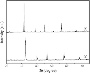
X-ray diffraction (XRD) pattern of the LSCF hollow fibre membrane is shown in Fig. 1a. The characteristic peaks of the rhombohedral perovskite phase were detected as reported elsewhere.38,39 In addition, the BSCN powder sintered at 1100 °C exhibited strong diffraction peaks with respective 2θ angles (Fig. 1b) agreeing with the single perovskite-type phase with cubic lattice symmetry.36Fig. 2 displays the morphology of BSCN perovskite powders calcined at 1100 °C for 5 h. It is observed that the BSCN particles agglomerated after the calcination process. Such agglomeration may prevent the uniform dispersion of BSCN particles in the coating solution and cause defects in surface of the modified hollow fibre membranes. Therefore, the post-treatment including ball-milling and sieving of the calcined BSCN powders is a critical step to break down the large agglomerates.
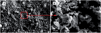 | ||
| Fig. 2 SEM images of BSCN powders calcined at 1100 °C for 5 h. (A) Low magnification; (B) high magnification. | ||
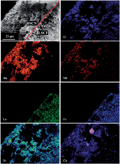
SEM images of unmodified and BSCN-coated LSCF hollow fibre membranes are comparatively displayed in Fig. 3. The typical outer and inner diameter of the fresh membrane is around 2.11 and 1.58 mm, respectively, as measured from Fig. 3A. The original membrane possesses a typical sandwich structure prepared by using water as the internal and external coagulants to prepare the hollow fibre precursors. Short finger-like pores are present near the outer and inner walls of the fibre, while a thick and fully densified layer exists in the centre of the fibre. Fig. 3B and C show the fully densified microstructure of the inner and outer surfaces with average grain size about 1 μm. The complete gas-tightness of the membranes was verified by the gas leaking test under the pressure difference of 2 bar at room temperature. SEM images of LSCF hollow fibre membrane coated by BSCN layer are shown in Fig. 3D–F. It is found that porous BSCN layer with thickness of about 50 μm (marked by the red arrow in Fig. 3D and red shapes in Fig. 3F) was successfully formed and firmly adhered on one or both surfaces of the membrane, suggesting that the single dip coating method is effective to deposit porous layer on the surface of LSCF membranes. Technically, the thickness of the porous layer can be tuned by varying the concentration of the coating slurry as well as the coating times. It can also be seen that the agglomerate size of BSCN particles is larger than the grain size from the LSCF hollow fibre membrane. Hence, the porous BSCN layer provides not only more pathway for the diffusion of oxygen to or from surface of membrane, but also more surface area to facilitate the surface exchange reaction. Fig. 4 shows the EDS element mapping of the SEM image in the area of interface (marked as the red line in the SEM image) between BSCN and LSCF layer. As can be seen, some elements of Sr, Co and O are homogeneously distributed over the entire BSCN-O sample. However, La/Fe or Ba can only be detected in the LSCF or BSCN coating layer, respectively. However, a minor amount of Nb penetrated into the LSCF layer after high temperature treatment. This may cause the variation of the oxygen permeation performance of the coated LSCF membranes.
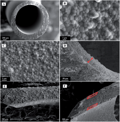 | ||
| Fig. 3 SEM images of unmodified (A–C) and BSCN-coated (D–F) LSCF hollow fibre membranes. (A) Cross sectional view; (B) inner surface; (C) outer surface; (D) BSCN-I, (E) BSCN-O and (F) BSCN-B. | ||
Fig. 5 presents the oxygen permeation fluxes against temperature for BSCN-coated LSCF hollow fibre membranes together with the unmodified LSCF hollow fibre for comparison purpose. The oxygen permeation is a temperature-activation process and at room temperature the perovskite membrane displayed no permeation. These fluxes increased steadily with the temperature due to the enhancement of oxygen ionic bulk-diffusion and the surface-exchange rate. It also can be seen that all the BSCN-coated membranes exhibit noticeably higher oxygen permeation fluxes than the unmodified membrane. We also observed that at similar operating conditions, the flux improvement of BSCN-O was larger than that of BSCN-I. This reflects the surface (facing air side) reaction resistance of oxygen reduction is larger than the reverse reaction of oxygen ion oxidation in the permeate side. Major improvements in oxygen permeation flux are noticeable at low temperature regime. For instance, at 800 °C and the sweep gas rate of 100 mL min−1, the oxygen permeation flux through the unmodified LSCF membrane was 0.059 mL min−1 cm−2; after surface modification, the value was improved to 0.126, 0.185 and 0.383 mL min−1 cm−2 with the enhancement factor of 2.1, 3.1 and 6.5 with respect to BSCN-I, BSCN-O and BSCN-B, respectively. Noteworthy is that at this stage it is difficult to explain why at lower temperatures like 800 °C, the improvement factor of surface modification on both sides is closer to the value of the multiplication of the two improvement factors from single modification of BSCN-I and BSCN-O.
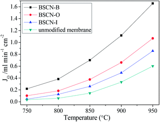 | ||
| Fig. 5 Oxygen permeation through BSCN-coated and unmodified LSCF hollow fibre membranes (sweep gas rate of 100 mL min−1 in the fibre lumen). | ||
At temperatures higher than 900 °C, the surface modification (BSCN-B or BSCN-O) improved the oxygen permeation flux larger than 1 mL min−1 cm−2, a target specified for commercial consideration by Steele in 1992.40 However, this target could not be reached by using the unmodified membrane even the temperature was increased to 950 °C. High oxygen permeation at lower temperature will make the coated LSCF membrane closer for large scale applications. The fact that the oxygen permeation flux can be improved by coating a porous BSCN layer indicates that the coated membranes have two significant advantages over the unmodified one: (1) the BSCN layer can remarkably enhance the surface exchange reaction rate; (2) the porous layer provides more surface area and facilitates the diffusion of oxygen molecules.
The percentage improvements of oxygen permeation for the BSCN-modified hollow fibre membranes are plotted against operating temperature in Fig. 6. It can be seen that all modified membranes had a bigger improvement at lower temperature regime, indicating the relative limiting step of the oxygen permeation process changed with the operating conditions. At lower temperature, the surface exchange reaction was the main rate-determining step for the oxygen permeation process. However, as the temperature further increased, the relative limiting effect of the bulk diffusion gradually became more noticeable. As a result, the enhancement of oxygen permeation by surface modification was relatively reduced. Nevertheless, the modified membranes still gave much higher oxygen permeation fluxes than that of the unmodified membrane even the temperature up to 950 °C. Similar effect of coated LSCF layer on LSCF hollow fibre membrane was also reported by Tan et al.26
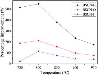 | ||
| Fig. 6 Percentage improvements of oxygen permeation for modified hollow fibre membranes as a function of temperature. | ||
Fig. 7 shows the oxygen permeation fluxes against sweep gas flow rates at different operating temperatures. The oxygen permeation flux increment with the increasing sweep gas rate is mainly due to the enlarged oxygen gradient by lowering the permeate side oxygen partial pressure. For example, at 950 °C, increasing the sweep gas rate from 50 to 200 mL min−1 slightly raised the oxygen permeation flux though the unmodified and BSCN-B membranes from 0.56 to 0.66 and 1.44 to 1.92 mL min−1 cm−2, respectively. Furthermore, the operating temperature plays a more important role in oxygen permeation than the concentration driving force for oxygen permeation in these membranes. For instance, the oxygen permeation flux though the unmodified and BSCN-B membranes increased dramatically from 0.04 to 0.66 and 0.21 to 1.92 mL min−1 cm−2, respectively, as the operating temperature increased from 750 to 950 °C at constant sweep gas rate of 200 mL min−1.
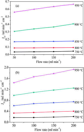 | ||
| Fig. 7 Effects of helium sweep rate on the oxygen permeation fluxes through unmodified (a) and BSCN-B (b) hollow fibre membranes. | ||
In comparison with the literature data as showing Table 1, the unmodified LSCF membrane possessed the same oxygen flux as that from the previous study.26 The oxygen flux of the coated LSCF membrane was largely improved but still less than Ba0.5Sr0.5Co0.8Fe0.2O3−δ (BSCF) hollow fibre membrane. It should be noted that BSCF and LSCF are still the state of the art of the perovskite materials which present two typical membranes with highest flux/lower material stability and intermediate flux/higher material stability, respectively.
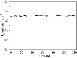
A long-term operation test was conducted on the BSCN-B membrane under the operating conditions of 900 °C and 100 mL min−1 sweep gas rate. The oxygen permeation flux potted against the operation time is shown in Fig. 8. As can be seen, the membrane system reached steady state and gave a stable oxygen permeation flux value at 1.11 mL min−1 cm−2 for the entire operation period of 120 h at 900 °C. This implies that the BSCN-B membrane shows high stability at least under the investigated operational conditions. Membrane surface modification can also be completed via surface acid reaction to make the original dense and smooth surface more porous by etching away part of the surface layer.25 However, such etching strategy may damage the mechanical strength of the hollow fibre membrane.
4 Conclusions
The surface modification of gas-tight La0.6Sr0.4Co0.2Fe0.8O3−δ (LSCF) hollow fibre membranes was conducted by Ba0.5Sr0.5Co0.9Nb0.1O3−δ (BSCN) perovskite porous layer. It was found that porous BSCN layer can be successfully formed and firmly attached to the membrane surface. All the BSCN-coated membranes, especially the inner and outer surface modified one, exhibited noticeably higher oxygen permeation fluxes than the unmodified hollow fibre membrane. The results also indicate that the relative limiting step of the oxygen permeation process changes from the surface exchange reaction to bulk diffusion with temperature increase. Furthermore, the modified membrane also exhibited high oxygen permeation stability for the entire investigated 120 hour-operation at 900 °C without flux decay.Acknowledgements
The authors gratefully acknowledge the support from the Australia Research Council Future Fellowship (FT120100178) program and Taishan Scholar Construction Project of Shandong Province (200824085). The authors would like to thank Dr Fei Li for the assistance on the EDS elemental mapping.References
- S. M. Hashim, A. R. Mohamed and S. Bhatia, Adv. Colloid Interface Sci., 2010, 160, 88–100 CrossRef CAS PubMed.
- A. Y. Ku, P. Kulkarni, R. Shisler and W. Wei, J. Membr. Sci., 2011, 367, 233–239 CrossRef CAS PubMed.
- A. Leo, S. Liu and J. C. Diniz da Costa, Int. J. Greenhouse Gas Control, 2009, 3, 357–367 CrossRef CAS PubMed.
- X. Dong and W. Jin, Curr. Opin. Chem. Eng., 2012, 1, 163–170 CrossRef CAS PubMed.
- X. Zhu, H. Liu, Y. Cong and W. Yang, Chem. Commun., 2012, 48, 251–253 RSC.
- S. S. Hashim, A. R. Mohamed and S. Bhatia, Renewable Sustainable Energy Rev., 2011, 15, 1284–1293 CrossRef CAS PubMed.
- Y. Wei, W. Yang, J. Caro and H. Wang, Chem. Eng. J., 2013, 220, 185–203 CrossRef CAS PubMed.
- W. Li, T. F. Tian, F. Y. Shi, Y. S. Wang and C. S. Chen, Ind. Eng. Chem. Res., 2009, 48, 5789–5793 CrossRef CAS.
- X. Zhu, M. Li, H. Liu, T. Zhang, Y. Cong and W. Yang, J. Membr. Sci., 2012, 394, 120–130 CrossRef PubMed.
- C. S. Chen, H. Kruidhof, H. J. M. Bouwmeester, H. Verweij and A. J. Burggraaf, Solid State Ionics, 1996, 86, 569–572 CrossRef.
- M. Sun, X. Chen and L. Hong, RSC Adv., 2014, 4, 5618–5625 RSC.
- S. P. S. Badwal and F. T. Ciacchi, Adv. Mater., 2001, 13, 993–996 CrossRef CAS.
- H. Wang, C. Tablet, A. Feldhoff and J. Caro, Adv. Mater., 2005, 17, 1785–1788 CrossRef CAS.
- Y. Liu, X. Zhu, M. Li, H. Liu, Y. Cong and W. Yang, Angew. Chem., Int. Ed., 2013, 52, 3232–3236 CrossRef CAS PubMed.
- X. Zhu, H. Wang and W. Yang, Chem. Commun., 2004, 1130–1131 RSC.
- R. Bredesen, I. Kumakiri and T. Peters, in Membrane Operations: Innovative Separations and Transformations, ed. E. Drioli and L. Giorno, Wiley-VCH, Weinheim, 2009, ch. 9, pp. 195–216 Search PubMed.
- Y. Wei, H. Liu, J. Xue, Z. Li and H. Wang, AIChE J., 2011, 57, 975–984 CrossRef CAS.
- D. Schlehuber, E. Wessel, L. Singheiser and T. Markus, J. Membr. Sci., 2010, 351, 16–20 CrossRef CAS PubMed.
- X. Tan, N. Liu, B. Meng, J. Sunarso, K. Zhang and S. Liu, J. Membr. Sci., 2012, 389, 216–222 CrossRef CAS PubMed.
- Y. Y. Liu, X. Tan and K. Li, Catal. Rev.: Sci. Eng., 2006, 48, 145–198 CAS.
- J. Sunarso, S. Baumann, J. M. Serra, W. A. Meulenberg, S. Liu, Y. S. Lin and J. C. Diniz da Costa, J. Membr. Sci., 2008, 320, 13–41 CrossRef CAS PubMed.
- A. Leo, S. Smart, S. Liu and J. C. Diniz da Costa, J. Membr. Sci., 2011, 368, 64–68 CrossRef CAS PubMed.
- A. Leo, S. Liu and J. C. Diniz da Costa, J. Membr. Sci., 2009, 340, 148–153 CrossRef CAS PubMed.
- T. Kida, S. Ninomiya, K. Watanabe, N. Yamazoe and K. Shimanoe, ACS Appl. Mater. Interfaces., 2010, 2, 2849–2853 CAS.
- Z. Wang, H. Liu, X. Tan, Y. Jin and S. Liu, J. Membr. Sci., 2009, 345, 65–73 CrossRef CAS PubMed.
- X. Tan, Z. Wang, H. Liu and S. Liu, J. Membr. Sci., 2008, 324, 128–135 CrossRef CAS PubMed.
- J. P. Kim, J. H. Park, E. Magnone and Y. Lee, Mater. Lett., 2011, 65, 2168–2170 CrossRef CAS PubMed.
- K. Zhang, J. Sunarso, Z. Shao, W. Zhou, C. Sun, S. Wang and S. Liu, RSC Adv., 2011, 1, 1661–1676 RSC.
- X. Tan, Z. Wang and K. Li, Ind. Eng. Chem. Res., 2010, 49, 2895–2901 CrossRef CAS.
- A. Leo, S. Smart, S. Liu and J. C. Diniz da Costa, J. Membr. Sci., 2011, 368, 64–68 CrossRef CAS PubMed.
- K. Efimov, T. Halfer, A. Kuhn, P. Heitjans, J. Caro and A. Feldhoff, Chem. Mater., 2010, 22, 1540–1544 CrossRef CAS.
- J. Sunarso, S. Liu and Y. S. Lin, Energy Environ. Sci., 2011, 4, 2516–2519 CAS.
- H. Wang, S. Werth, T. Schiestel and J. Caro, Angew. Chem., Int. Ed., 2005, 44, 6906–6909 CrossRef CAS PubMed.
- T. Schiestel, M. Kilgus, S. Peter, K. J. Caspary, H. Wang and J. Caro, J. Membr. Sci., 2005, 258, 1–4 CrossRef CAS PubMed.
- C. Huang, D. Chen, Y. Lin, R. Ran and Z. Shao, J. Power Source, 2010, 195, 5176–5184 CrossRef CAS PubMed.
- J. Zhao, K. Zhang, D. Gao, Z. Shao and S. Liu, Sep. Purif. Technol., 2010, 71, 152–159 CrossRef CAS PubMed.
- X. Tan, Y. Liu and K. Li, Ind. Eng. Chem. Res., 2005, 44, 61–66 CrossRef CAS.
- D. Waller, J. A. Lane, J. A. Kilner and B. C. H. Steele, Mater. Lett., 1996, 27, 225–228 CrossRef CAS.
- G. C. Kostogloudis and C. Ftikos, Solid State Ionics, 1999, 126, 143–151 CrossRef CAS.
- B. C. H. Steele, Mater. Sci. Eng., B, 1992, 13, 79–87 CrossRef.
- S. Liu and G. R. Gavalas, J. Membr. Sci., 2005, 246, 103–108 CrossRef CAS PubMed.
| This journal is © The Royal Society of Chemistry 2014 |

