Synthesis and electrochemical properties of conducting polyaniline/graphene hybrids by click chemistry†
Madeshwaran Sekkarapatti Ramasamy,
Sibdas Singha Mahapatra,
Dong Hun Yi,
Hye Jin Yoo and
Jae Whan Cho*
Department of Organic and Nano System Engineering, Konkuk University, Seoul 143-701, Republic of Korea. E-mail: jwcho@konkuk.ac.kr
First published on 21st May 2014
Abstract
Conducting polyaniline nanofiber-grafted graphene oxide (PANINF-GO) hybrids were prepared by click coupling of azide-functionalized GO (GO-N3) with aniline monomer-functionalized GO (GO-f-aniline) and then in situ rapid mixing polymerization in the presence of aniline. The successful synthesis of the PANINF-GO hybrids was confirmed by Fourier transform infrared spectroscopy, X-ray photoelectron spectroscopy, and thermogravimetric analysis. The chemical and electronic structures of polyaniline and GO could be largely preserved during covalent grafting via click chemistry, which was attributed to the enhanced electrical properties of the hybrids. High resolution transmission electron microscopy and scanning electron microscopy observations showed that the polyaniline was embedded on the GO surface in the form of a fibrous morphology with covalent bonding. The click coupled hybrids of PANINFs and GO in this study demonstrated excellent electrochemical properties and high stability over repeated cycles.
1. Introduction
Polyaniline (PANI) is distinct among conducting polymers because of its unique physical and chemical properties, high capacitance, good environmental stability, and ease of preparation.1,2 Polyaniline nanofibers (PANINFs), prepared using a rapid mixing process, have superior properties because of their high surface areas, and have received a great deal of attraction in applications such as sensors, supercapacitors, actuators, and memory devices.3–9 However, PANI displays poor stability during the charge–discharge process, which often restricts its use in these applications. To overcome the weak performance of PANI, PANI composites have been prepared via the incorporation of a variety of carbon-based materials, including carbon nanotubes, mesoporous carbon, and activated carbon, into PANI.Graphene, an intriguing two-dimensional nanocarbon material, may be an ideal candidate for PANI composites because it has good electrical and mechanical properties, superior stability, high surface area, broad electrochemical window, and low manufacturing cost compared to carbon nanotubes.10–12 PANI and graphene composites have been prepared by employing in situ polymerization of aniline in the presence of a graphene oxide (GO) dispersion in acidic solution, followed by reduction to restore the electronic structure of graphene.13,14 However, during the reduction step, the electronic structure of PANI in the composites may change from a conducting emeraldine base state to a neutral lucoemeraldine base state, and thus additional reoxidation is necessary to recover the conducting emeraldine state of the PANI. Ultimately, the reduction and reoxidation steps result in some unavoidable electronic change, and influence the final electrical properties of the PANI composites. Therefore, a more effective method for preparing PANI-GO composites without sacrificing the intrinsic properties of the two components is required. Mao et al. reported the preparation of homogeneous PANI-graphene composites without disturbing the electronic structure of PANI. In their study, GO was first reduced in the presence of surfactants, and aniline was then polymerized in situ on the surface of the surfactant-stabilized graphene; the resultant composites showed high specific capacitance of 526 F g−1 and good cycling stability.15 Kumar et al. reported the facile covalent functionalization of PANI-reduced graphene oxide composites, where GO was reduced in situ to a certain extent during functionalization with PANI, which resulted in enhanced properties.16
Herein, we report a simple and effective method of preparing PANI-GO hybrids with superior electrochemical properties. Our method involves the covalent functionalization of GO with PANI via a click coupling reaction, which can render GO partially reduced during the covalent functionalization without the need for post reduction and reoxidation steps. The click chemistry reaction is facile and versatile because of its mild reaction conditions, high yield, lack of by-product formation, and amenability to a variety of solvents.17–19 By using click chemistry to prepare PANI-GO composites, the intrinsic properties of PANI and GO can be relatively preserved during the GO functionalization process, and thus the superior electrochemical properties of the PANI-GO hybrids can be obtained.
2. Experimental
2.1. Materials
GO was received from Nanoinnova Technologies (Madrid, Spain), while sodium azide, acetonitrile, aniline, ammonium peroxydisulfate, copper (I) iodide (CuI), and N,N'-dimethylformamide (DMF) were purchased from Sigma Aldrich, Korea. N,N-Diisopropylethylamine (DIPEA) and hydrochloric acid were obtained from Tokyo Chemical Industry Co. Ltd., Japan, and Shinyo Pure Chemicals Co. Ltd., Japan, respectively.2.2. Synthesis of azide-functionalized GO
Azide-functionalized GO (GO-N3) was synthesized as previously reported.20 GO (300 mg) was dispersed in an acetonitrile and water mixture (15 mL, 1![[thin space (1/6-em)]](https://www.rsc.org/images/entities/char_2009.gif) :
:![[thin space (1/6-em)]](https://www.rsc.org/images/entities/char_2009.gif) 1 v/v) by bath-type sonication for 30 min. Sodium azide (370 mg) was then added, and the reaction mixture was heated at reflux at 70 °C under a nitrogen atmosphere for one week. After cooling to room temperature, dichloromethane (60 mL) was added, and the resulting coagulation was filtered, washed with distilled water and acetonitrile several times, and dried at 50 °C under vacuum to afford GO-N3 as a solid product.
1 v/v) by bath-type sonication for 30 min. Sodium azide (370 mg) was then added, and the reaction mixture was heated at reflux at 70 °C under a nitrogen atmosphere for one week. After cooling to room temperature, dichloromethane (60 mL) was added, and the resulting coagulation was filtered, washed with distilled water and acetonitrile several times, and dried at 50 °C under vacuum to afford GO-N3 as a solid product.
2.3. Synthesis of GO functionalized with aniline via a click reaction
GO functionalized with aniline (GO-f-aniline) was synthesized by employing a click reaction involving azide-functionalized GO and the ethynyl groups at the end of 4-ethynyl aniline. A two-necked round bottom flask was charged with CuI (30 mg), DIPEA (0.9 mL), and DMF, and stirred under a nitrogen atmosphere. After the reaction mixture turned yellow, a solution of 4-ethynylaniline (900 mg) dissolved in DMF (10 mL) was added, and the reaction was stirred for an additional 30 min. GO-N3 (100 mg) dispersion in DMF (20 mL) was transferred into the reaction flask, and a click reaction was carried out by stirring the reaction at 50 °C for 2 days. The solid was separated from the reaction mixture by filtration, and washed several times with methanol and distilled water, followed by drying under vacuum at 50 °C to yield GO-f-aniline.2.4. Synthesis of PANINF-GO hybrids
Covalently bonded PANINF-GO hybrids were prepared via the in situ polymerization of aniline in a suspension of GO-f-aniline under acidic conditions. The weight feed ratio of aniline to GO-f-aniline was varied from 95![[thin space (1/6-em)]](https://www.rsc.org/images/entities/char_2009.gif) :
:![[thin space (1/6-em)]](https://www.rsc.org/images/entities/char_2009.gif) 5, 90
5, 90![[thin space (1/6-em)]](https://www.rsc.org/images/entities/char_2009.gif) :
:![[thin space (1/6-em)]](https://www.rsc.org/images/entities/char_2009.gif) 10, and 80
10, and 80![[thin space (1/6-em)]](https://www.rsc.org/images/entities/char_2009.gif) :
:![[thin space (1/6-em)]](https://www.rsc.org/images/entities/char_2009.gif) 20, and the resulting hybrids were named PANIGO5, PANIGO10, and PANIGO20, respectively. In a typical reaction, aniline (250 mg, 0.68 mmol) was dissolved in 1 M HCl (8.95 mL). GO-f-aniline was added to the solution, and the resulting mixture was bath-sonicated for 1 h. The reaction mixture was vigorously stirred to ensure sufficient mixing of aniline and GO-f-aniline before the polymerization began. Ammonium peroxydisulfate (in a 1
20, and the resulting hybrids were named PANIGO5, PANIGO10, and PANIGO20, respectively. In a typical reaction, aniline (250 mg, 0.68 mmol) was dissolved in 1 M HCl (8.95 mL). GO-f-aniline was added to the solution, and the resulting mixture was bath-sonicated for 1 h. The reaction mixture was vigorously stirred to ensure sufficient mixing of aniline and GO-f-aniline before the polymerization began. Ammonium peroxydisulfate (in a 1![[thin space (1/6-em)]](https://www.rsc.org/images/entities/char_2009.gif) :
:![[thin space (1/6-em)]](https://www.rsc.org/images/entities/char_2009.gif) 4 molar ratio with aniline) in 1 M HCl was rapidly poured into the reaction mixture while maintaining vigorous stirring. Polymerization was observed within ∼5 min, as indicated by the appearance a PANI emeraldine salt with a characteristic green color. The polymerization was allowed to proceed overnight at room temperature, and the reaction mixture was diluted with distilled water. The PANI-GO hybrids were obtained by the filtration of the reaction mixtures, followed by rigorous washing of the resulting solids with water, ethanol, and hexane.
4 molar ratio with aniline) in 1 M HCl was rapidly poured into the reaction mixture while maintaining vigorous stirring. Polymerization was observed within ∼5 min, as indicated by the appearance a PANI emeraldine salt with a characteristic green color. The polymerization was allowed to proceed overnight at room temperature, and the reaction mixture was diluted with distilled water. The PANI-GO hybrids were obtained by the filtration of the reaction mixtures, followed by rigorous washing of the resulting solids with water, ethanol, and hexane.
2.5. Synthesis of PANINFs via a rapid mixing reaction
For comparative purposes, pure PANINFs were prepared using a rapid mixing reaction, as reported in the literature.21 Aniline (300 mg, 3.2 mmol) was dissolved in 1 M HCl (10 mL). While maintaining vigorous stirring, ammonium peroxydisulfate (180 mg, 0.8 mmol) dissolved in 1 M HCl (10 mL) was rapidly poured into the aniline solution, and the reaction mixture was stirred overnight at room temperature. The reaction mixture was diluted with distilled water, and the precipitated PANINFs were collected via filtration, and isolated as a green color powder. The PANINFs were purified by repetitive washings with water, ethanol, and hexane, and then dried under vacuum at 50 °C.2.6. Characterization
X-ray photoelectron spectroscopy (XPS) measurements were conducted on an XPS (ESCSA 2000) spectrophotometer. Raman spectra were recorded on a LabRam HR Ar-ion laser 514 nm, Jobin-Yvon spectrometer. Fourier transform infrared spectroscopy (FT-IR) measurements were performed on a Jasco FT-IR 300E apparatus (Tokyo, Japan). UV-vis absorption spectra of the samples dispersed in ethanol were obtained on a Hitachi UV spectrophotometer (U2001, Tokyo, Japan). The morphology of the samples was characterized by scanning electron microscopy (FE-SEM, S-4300SE, and Hitachi), and high resolution transmission electron microscopy (HR-TEM, JEM 2100, JEOL). In the HR-TEM measurements, the samples were dispersed in ethanol, and dropped on 400-mesh copper grids with supporting carbon films. Thermogravimetric analysis (TGA) of the samples was carried out under a nitrogen atmosphere using a TA Q500 thermal analyzer at a heating rate of 5 °C min−1. Cyclic voltammetry experiments were carried out using an electrochemical workstation (CHI 660B, CH Instruments, USA), with the output recorded using a desktop computer. A cell with a volume of 75 mL, standard calomel used as the reference electrode, PANI-GO hybrids used as working electrodes, and a platinum electrode used as the auxiliary electrode, was used throughout the electrochemical measurements. The working electrode was prepared by dropping a solution of the samples onto a glassy carbon electrode, followed by drying. Sulfuric acid (2 M) was used as the electrolyte throughout this study. All of the electrochemical measurements were carried in the potential range of −0.2 V to 1 V, with a scan rate of 50 mV s−1.3. Results and discussion
PANINFs were covalently functionalized with GO using a click chemistry approach, as shown in Scheme 1. Firstly, azide-functionalized GO was prepared by the treatment of GO with sodium azide in a 1![[thin space (1/6-em)]](https://www.rsc.org/images/entities/char_2009.gif) :
:![[thin space (1/6-em)]](https://www.rsc.org/images/entities/char_2009.gif) 1 v/v mixture of acetonitrile and water. The aniline monomer (4-ethynylaniline) was then grafted with GO by a click reaction between GO-N3 and 4-ethynylaniline. Finally, the PANINF-GO hybrids were obtained by the rapid mixing of ammonium peroxydisulfate (in 1 M HCl) with a homogeneous mixture of GO-f-aniline in 1 M HCl, containing various molar ratios of the monomer aniline.
1 v/v mixture of acetonitrile and water. The aniline monomer (4-ethynylaniline) was then grafted with GO by a click reaction between GO-N3 and 4-ethynylaniline. Finally, the PANINF-GO hybrids were obtained by the rapid mixing of ammonium peroxydisulfate (in 1 M HCl) with a homogeneous mixture of GO-f-aniline in 1 M HCl, containing various molar ratios of the monomer aniline.
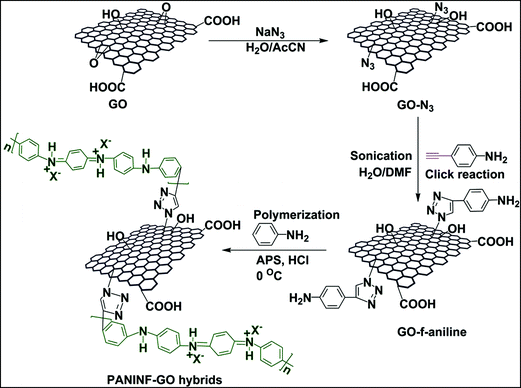 | ||
| Scheme 1 Schematic illustration of the covalent grafting of 4-ethynylaniline monomer with GO using a click reaction, followed by in situ rapid mixing polymerization to prepare PANINF-GO hybrids. | ||
Fig. 1(a)–(c) displays the wide scan XPS results for GO, GO-N3, and GO-f-aniline, respectively. The XPS spectrum of GO shows only carbon and oxygen peaks, whereas the XPS spectra of GO-N3 and GO-f-aniline exhibit carbon, oxygen, and nitrogen peaks. It can also be seen that the nitrogen content of GO-f-aniline is higher than that of GO-N3, which is due to the successful azidation of GO by grafting with 4-ethynylaniline (Table 1). Fig. 1(d)–(f) shows the carbon 1s core-level spectra for GO, GO-N3, and GO-f-aniline, respectively. The spectrum of GO has peaks at 284.6, 286.41, and 288.33 eV, corresponding to the C–C, C–O, and C![[double bond, length as m-dash]](https://www.rsc.org/images/entities/char_e001.gif) O groups, respectively because of the presence of oxygen-containing species such as epoxy, hydroxyl, and carbonyl groups.22 Meanwhile, it can also be seen that the peak intensity corresponding to C–O-containing species was considerably decreased in GO-N3 and GO-f-aniline, confirming that the electronic structure of GO was restored to a certain extent. Or in other words, the sp2 network of GO was partially restored, leading to improved π–π interaction between the PANINFs and GO. These results explain that the GO was simultaneously reduced and covalently grafted with monomer, 4-ethynylaniline by click chemistry reaction, and followed by the oxidative polymerization to yield partially reduced GO-PANI composites. The covalent functionalization of GO via click chemistry in this study may be the simple and effective route requiring no separate reduction process for GO.23
O groups, respectively because of the presence of oxygen-containing species such as epoxy, hydroxyl, and carbonyl groups.22 Meanwhile, it can also be seen that the peak intensity corresponding to C–O-containing species was considerably decreased in GO-N3 and GO-f-aniline, confirming that the electronic structure of GO was restored to a certain extent. Or in other words, the sp2 network of GO was partially restored, leading to improved π–π interaction between the PANINFs and GO. These results explain that the GO was simultaneously reduced and covalently grafted with monomer, 4-ethynylaniline by click chemistry reaction, and followed by the oxidative polymerization to yield partially reduced GO-PANI composites. The covalent functionalization of GO via click chemistry in this study may be the simple and effective route requiring no separate reduction process for GO.23
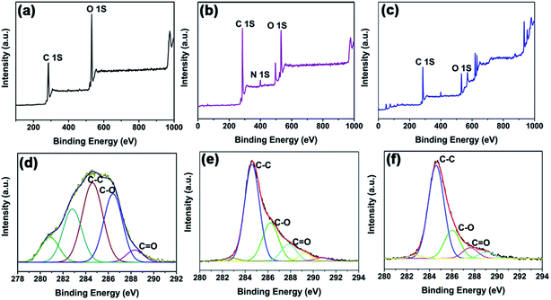 | ||
| Fig. 1 Wide-scan X-ray photoelectron spectra of (a) GO, (b) GO-N3, and (c) GO-f-aniline, and high-resolution C 1s spectra of (d) GO, (e) GO-N3, and (f) GO-f-aniline. | ||
| Sample | Carbon (%) | Oxygen (%) | Nitrogen (%) |
|---|---|---|---|
| GO | 70.2 | 29.8 | 0.0 |
| GO-N3 | 76.5 | 19.6 | 3.9 |
| GO-f-aniline | 78.3 | 16.7 | 5 |
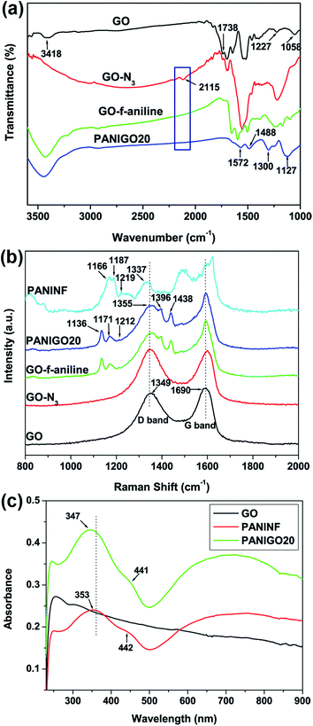
FT-IR measurements were carried out to analyze the covalent grafting of PANINFs onto the GO surface. As shown in Fig. 2(a), the FT-IR spectrum of GO exhibited characteristic peaks corresponding to O–H (hydroxyl) and C![[double bond, length as m-dash]](https://www.rsc.org/images/entities/char_e001.gif) O (carboxylic acid) groups at 3418 cm−1 and 1738 cm−1, respectively.24 However, after the treatment of GO with sodium azide, a new peak corresponding to GO-N3 was observed around 2115 cm−1, which was attributed to the presence of N3 groups on the GO surface. The reaction of GO-N3 with 4-ethynylaniline in the presence of a copper catalyst led to the conversion of the N3 groups into triazole rings, as evidenced by the disappearance of the N3 peak at 2115 cm−1 in the spectrum of GO-f-aniline. After the covalent grafting of PANINFs with GO, the FT-IR spectrum of PANIGO20 exhibited peaks around 1572 and 1488 cm−1, which were assigned to the C
O (carboxylic acid) groups at 3418 cm−1 and 1738 cm−1, respectively.24 However, after the treatment of GO with sodium azide, a new peak corresponding to GO-N3 was observed around 2115 cm−1, which was attributed to the presence of N3 groups on the GO surface. The reaction of GO-N3 with 4-ethynylaniline in the presence of a copper catalyst led to the conversion of the N3 groups into triazole rings, as evidenced by the disappearance of the N3 peak at 2115 cm−1 in the spectrum of GO-f-aniline. After the covalent grafting of PANINFs with GO, the FT-IR spectrum of PANIGO20 exhibited peaks around 1572 and 1488 cm−1, which were assigned to the C![[double bond, length as m-dash]](https://www.rsc.org/images/entities/char_e001.gif) C stretching deformations of the quinoid and benzenoid structures of PANI, respectively, with the intensity of the quinoid band less than that of the benzenoid band. In addition, the presence of a strong band around 1127 cm−1 was attributed to the N–Q–N–Q stretch of the quinoid ring, which clearly indicates the presence of the protonated emeraldine state of PANI on the GO surface, which has a higher degree of electron delocalization.25
C stretching deformations of the quinoid and benzenoid structures of PANI, respectively, with the intensity of the quinoid band less than that of the benzenoid band. In addition, the presence of a strong band around 1127 cm−1 was attributed to the N–Q–N–Q stretch of the quinoid ring, which clearly indicates the presence of the protonated emeraldine state of PANI on the GO surface, which has a higher degree of electron delocalization.25
Raman spectroscopy measurements were also carried out to study the interaction between GO and the PANINFs (Fig. 2(b)). The broad G band at 1590 cm−1 corresponds to the doubly degenerate zone-center E2g mode, whereas the D band at 1349 cm−1 is due to the sp3 carbons generated during the oxidation of GO.26 In the spectrum of the PANIGO20 hybrid, the existence of peaks at 1171 cm−1, 1355 cm−1, and 1440 cm−1 were ascribed to C–H bending of the quinoid ring, C–N+ stretching, and C![[double bond, length as m-dash]](https://www.rsc.org/images/entities/char_e001.gif) N stretching vibrations of PANI, respectively, indicating the formation of PANI on the GO surface.27 In contrast, the PANIGO20 hybrid showed a shift of the C–N+ stretching band toward a higher wavelength relative to the pure PANINFs, indicating a strong interaction between GO and the PANINFs. N 1s core-level XPS spectra of GO-N3 and GO-click-aniline was displayed in Fig. S1.† GO-N3 shows peaks at 398.5, 399.9 and 401.6 eV respectively (Fig. S1(a)†). Fig. S1(b)† shows the N 1s XPS spectra of GO-click-aniline obtained after the click reaction with 4-ethynylaniline using CuI (30 mg), DIPEA as catalyst. The absence of peak at 401.6 eV was attributed to the success of click reaction.
N stretching vibrations of PANI, respectively, indicating the formation of PANI on the GO surface.27 In contrast, the PANIGO20 hybrid showed a shift of the C–N+ stretching band toward a higher wavelength relative to the pure PANINFs, indicating a strong interaction between GO and the PANINFs. N 1s core-level XPS spectra of GO-N3 and GO-click-aniline was displayed in Fig. S1.† GO-N3 shows peaks at 398.5, 399.9 and 401.6 eV respectively (Fig. S1(a)†). Fig. S1(b)† shows the N 1s XPS spectra of GO-click-aniline obtained after the click reaction with 4-ethynylaniline using CuI (30 mg), DIPEA as catalyst. The absence of peak at 401.6 eV was attributed to the success of click reaction.
The dispersibility of GO in the PANINFs matrix was investigated by UV-vis spectroscopy (Fig. 2(c)). Pure PANINFs showed absorption bands at 442 and 755 nm (free carrier tail) for polaron bands, with a peak at 353 nm due to the π–π* electron transition in the benzenoid rings. In contrast, the PANIGO20 nanohybrid exhibited polaron absorption maxima at 441 and 724 nm, which reflects the fact that the PANINFs were present in the emeraldine salt form on the GO surface. In addition, the UV peak for PANIGO20 corresponding to the π–π* electron transition of the benzenoid rings was blue shifted 6 nm compared to that of the pure PANINFs, indicating π–π interactions between the PANINFs and GO. Fig. 2(c) shows that there exists significant interfacial interaction between the PANINFs and the GO sheets because of covalent grafting.28,29 The X-ray diffraction patterns of GO, PANINF, GO-f-aniline, and PANIGO composites are also obtained (Fig. S2†). The GO sample exhibits the sharp (001) peak at 2θ = 11.6°, which is due to the interlayer spacing of layered GO sheets. However, the (001) peak almost disappeared after click coupling with appearance of the broad peak at 2θ = 25.4° due to partial reduction of GO during the covalent grafting process.16 The broad X-ray peak at 2θ = 25.3° in the pure PANINF corresponds to some crystalline characteristic of bulk PANINFs. For the PANIGO hybrids, the (001) peak of GO almost disappeared and the broad peak at 2θ = 25.3° appeared due to presence of PANINFs, indicating exfoliation of GO by covalent grafting with PANINF.
TGA measurements were carried out to analyze both the thermal stability and the degree of functionalization of covalently grafted PANINFs with GO. All of the samples exhibited minor weight loss in the region of 120 °C due to the loss of surface-bound water molecules (Fig. S3†). A weight loss of 24.8 wt% was observed from 170 to 230 °C in GO because of either the pyrolysis or decomposition of labile oxygen functional groups, while at the same temperature range, GO-f-aniline exhibited weight losses of only 2.2 wt%, indicating a decrease in oxygen content during the covalent grafting process. After in situ polymerization, a sharp weight loss from 400 to 700 °C was observed for the PANIGO20 hybrids, likely because of the degradation of the PANI backbone. At the same time, the thermal stability of the hybrids was significantly increased; the pure PANINFs showed a weight loss of ∼40 wt% around 500.8 °C, whereas PANIGO20 showed an identical weight loss around 609.5 °C, indicating an increase in thermal stability of ∼108.7 °C. The enhanced thermal stability exhibited by the nanohybrids can be attributed to the restricted chain mobility of the PANINFs due to the incorporation of GO.30,31
The morphology of GO, the PANINF-GO hybrids, and the pure PANINFs were observed using HR-TEM. As shown in Fig. 3, pure PANINFs (prepared via a rapid mixing process) showed uniform nanofiber morphology (hundreds of nanometers in length and ∼30–50 nm in width). In contrast, the GO sheets showed wrinkled, layer-like structures, which was attributed to the conversion of sp2 carbon sheets to sp3 sheets by harsh oxidation. The HR-TEM images of all of the hybrid samples clearly indicated that the PANINFs were embedded within the matrix of the GO sheets, which reflected the fact that the PANINFs were covalently grafted onto the surface of the GO. The width of the nanofibers coated onto the GO surface was found to be 20–30 nm.
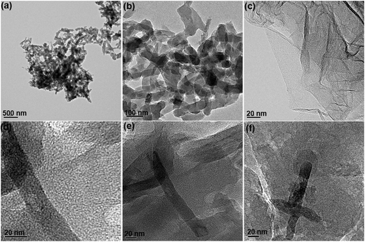 | ||
| Fig. 3 Transmission electron microscopy images of (a and b) PANINF, (c) GO, and hybrids of (d) PANIGO20, (e) PANIGO10, and (f) PANIGO5. | ||
FE-SEM measurements were carried out to further investigate the morphology of the hybrids. A well-defined, uniform nanofiber morphology was observed for the pure PANINFs, whereas the PANINFs in the hybrids were found to be either coated on the surface, or sandwiched in between the GO layers (Fig. 4) because of significant interaction between GO and the PANINFs. The formation of fibrous PANI on the GO surface can be explained as follows: because aniline is an electron donor, and GO is an electron acceptor, aniline monomer can be readily adsorbed onto the GO surface during the sonication of aniline and GO in the presence of HCl because of electrostatic interactions. Thus, PANINFs can be finely coated onto the GO surface by in situ polymerization. Consequently, the GO provided large nucleation sites for the growth of PANINFs on its surface.
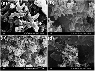 | ||
| Fig. 4 Scanning electron microscopy images of (a) PANINF, (b) PANIGO5, (c) PANIGO10, and (d) PANIGO20 hybrids. | ||
Electrochemical measurements were conducted to evaluate the cyclic voltammetry (CV) performances of the PANIGO hybrids relative to the pure PANINFs. All electrochemical measurements were recorded in a 2 M H2SO4 electrolyte solution with a potential range of −0.2 to 1 V at a scan rate of 50 mV s−1 using standard calomel as the reference electrode. As seen in Fig. 5, the CV curves are rectangular in shape, indicating good capacitance properties of the samples. For GO, some increase in the current with increasing the number of cycles to 50 cycles was observed, and one pair of redox peaks appeared according to transition between quinone–hydroquinone states (Fig. S4†).13 The pure PANINFs showed two pairs of redox peaks, attributed to the redox transition of PANI between a lucoemeraldine form (semiconducting) and a polaronic emeraldine form (conducting), and Faradaic transformation from an emeraldine state to a pernigraniline state.32 However, the hybrids exhibited high current density response and large CV loop areas compared to the pure PANINFs because of the partial reduction of GO by 4-ethynylaniline and high interfacial interaction between PANI and GO due to covalent bond formation between them. The electrochemical performance of the hybrids was also found to increase with increasing GO content because of the partial reduction of GO during covalent functionalization. The PANIGO20 hybrid exhibited the best electrochemical properties due to high GO content in the hybrids. Fig. 5(b) presents the CV curves obtained after 50 cycles at a scan rate of 50 mV s−1. It can be seen that there were no significant decreases in the current density response in any of the hybrids after the repeated cycles, which clearly indicates that the PANINF-GO hybrids in this study possess high cycling stability during electrochemical performance. The electrical conductivity of PANINF and PANINF-GO hybrids was also measured for the compressed pellets of the powder samples by the four probe method. The average electrical conductivities of PANINF, PANIGO5, PANIGO10, and PANIGO20 were found to be 0.5, 0.14, 1.4 and 1.1 S cm−1, respectively. Even though there was some deviation in the conductivity trend with the hybrid content, the increased conductivity of hybrids is attributed to the synergistic effect resulting from the covalent grafting of GO with PANINF.
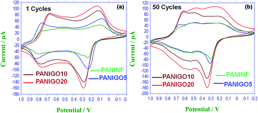 | ||
| Fig. 5 Cyclic voltammograms of PANINF and PANIGO hybrids recorded at a scan rate of 50 mV s−1 in (a) the 1st cycle and (b) the 50th cycle. | ||
4. Conclusions
The PANINFs were covalently grafted onto a GO surface using a simple and effective click reaction and an in situ rapid mixing polymerization method. The intrinsic properties of both the PANINFs and the GO were largely preserved during the grafting reaction. Because of the synergetic behavior of PANI and GO, the PANINF-GO hybrids showed a significant enhancement in their current density response in CV measurements compared to pure PANINFs, which indicates that this simple click reaction is a very effective technique for the preparation of nanocarbon-based hybrid materials with superior electrochemical properties.Acknowledgements
This work was supported by the Defense Acquisition Program Administration (DAPA), the Agency for Defense Development (ADD), and the National Research Foundation of Korea (NRF) grant funded by the Korean government (no. 2012R1A2A2A01015155).References
- A. Pud, N. Ogurtsov, A. Korzhenko and G. Shapoval, Prog. Polym. Sci., 2003, 28, 1701–1753 CrossRef CAS PubMed.
- M. G. Han, Y. J. Lee, S. W. Byun and S. S. Im, Synth. Met., 2001, 124, 337–343 CrossRef CAS.
- J. Huang and R. B. Kaner, J. Am. Chem. Soc., 2004, 126, 851–855 CrossRef CAS PubMed.
- J. Qiang, Z. Yu, H. Wu and D. Yun, Synth. Met., 2008, 158, 544–547 CrossRef CAS PubMed.
- N. R. Chiou and A. J. Epstein, Adv. Mater., 2005, 17, 1679–1683 CrossRef CAS.
- S. V. Jesse, D. Fowler, C. O. Baker, J. Huang, R. B. Kaner and B. H. Weiller, Small, 2005, 1, 624–627 CrossRef PubMed.
- J. Huang, S. Virji, B. H. Weiller and R. B. Kaner, J. Am. Chem. Soc., 2003, 125, 314–315 CrossRef CAS PubMed.
- D. Li, J. Huang and R. B. Kaner, Acc. Chem. Res., 2009, 42, 135–145 CrossRef CAS PubMed.
- X. Zhang, W. J. Goux and S. K. Manohar, J. Am. Chem. Soc., 2004, 126, 4502–4503 CrossRef CAS PubMed.
- K. P. Loh, Q. Bao, P. K. Ang and J. Yang, J. Mater. Chem., 2010, 20, 2277–2289 RSC.
- Q. Wu, Y. Xu, Z. Yao, A. Liu and G. Shi, ACS Nano, 2010, 4, 1963–1970 CrossRef CAS PubMed.
- S. H. Domingues, R. V. Salvatierra, M. M. Oliveira and A. J. G. Zarbin, Chem. Commun., 2011, 47, 2592–2594 RSC.
- K. Zhang, L. L. Zhang, X. S. Zhao and J. Wu, Chem. Mater., 2010, 22, 1392–1401 CrossRef CAS.
- S. Zhou, H. Zhang, Q. Zhao, X. Wang, J. Li and F. Wang, Carbon, 2013, 52, 440–450 CrossRef CAS PubMed.
- L. Mao, K. Zhang, H. S. O. Chan and J. Wu, J. Mater. Chem., 2012, 22, 80–85 RSC.
- N. A. Kumar, H. J. Choi, Y. R. Shin, D. W. Chang, L. Dai and J. B. Baek, ACS Nano, 2012, 6, 1715–1723 CrossRef CAS PubMed.
- S. K. Yadav, S. S. Mahapatra, J. W. Cho and J. Y. Lee, J. Phys. Chem. C, 2010, 114, 11395–11400 CAS.
- S. Rana and J. W. Cho, Nanoscale, 2010, 2, 2550–2556 RSC.
- Y. Pan, H. Bao, N. G. Sahoo, T. Wu and L. Li, Adv. Funct. Mater., 2011, 21, 2754–2763 CrossRef CAS.
- R. Salvio, S. Krabbenborg, W. J. M. Naber, A. H. Velders, D. N. Reinhoudt and W. G. V. Wiel, Chem.–Eur. J., 2009, 15, 8235–8240 CrossRef CAS PubMed.
- J. Huang and R. B. Kaner, Angew. Chem., Int. Ed., 2004, 43, 5817–5821 CrossRef CAS PubMed.
- D. Yang, A. Velamakanni, G. Bozoklu, S. Park, M. Stoller, R. D. Piner, S. Stankovich, I. Jung, D. A. Field, C. A. Ventrice Jr and R. S. Rouff, Carbon, 2009, 47, 145–152 CrossRef CAS PubMed.
- L. Q. Xu, Y. L. Liu, K. G. Neoh, E. T. Kang and G. D. Fu, Reduction of graphene oxide by aniline with its concomitant oxidative polymerization, Macromol. Rapid Commun., 2011, 32, 684–688 CrossRef CAS PubMed.
- D. Yu, Y. Yang, M. Durstock, J. B. Baek and L. Dai, ACS Nano, 2010, 4, 5633–5640 CrossRef CAS PubMed.
- J. An, J. Liu, Y. Zhou, H. Zho, Y. Ma, M. Li, M. Yu and S. Li, J. Phys. Chem. C, 2012, 116, 19699–19708 CAS.
- A. C. Ferrari, J. C. Meyer, V. Scardaci, C. Casiraghi, M. Lazzeri, F. Mauri, S. Piscanec, D. Jiang, K. S. Novoselov, S. Roth and A. K. Geim, Phys. Rev. Lett., 2006, 97, 187401–187404 CrossRef CAS.
- J. Yan, T. Wei, B. Shao, Z. Fan, W. Qian, M. Zhang and F. Wei, Carbon, 2010, 48, 487–493 CrossRef CAS PubMed.
- J. Xu, K. Wang, S. Z. Zu, B. H. Han and Z. Wei, ACS Nano, 2010, 4, 5019–5026 CrossRef CAS PubMed.
- X. Zhou, T. Wu, B. Hu, G. Yang and B. Han, Chem. Commun., 2010, 46, 3663–3665 RSC.
- S. Stankovich, D. A. Dikin, R. D. Piner, K. A. Kohlhaas, A. Kleinhammes, Y. Jia, Y. Wu, S. T. Nguyen and R. S. Ruoff, Carbon, 2007, 45, 1558–1565 CrossRef CAS PubMed.
- L. Ding, X. Wang and R. V. Gregory, Synth. Met., 1999, 104, 73–78 CrossRef CAS.
- H. Wang, Q. Hao, X. Yang, L. Lu and X. Wang, ACS Appl. Mater. Interfaces, 2010, 2, 821–828 CAS.
Footnote |
| † Electronic supplementary information (ESI) available: Fig. S1–S4. See DOI: 10.1039/c4ra03275f |
| This journal is © The Royal Society of Chemistry 2014 |

