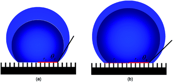
Pinning mechanism of advancing sessile droplet on superhydrophobic surfaces†
Jun Wu*,
Jun Xia*,
Wei Lei and
Bao-ping Wang
School of Electronic Science and Engineering, Southeast University, Nanjing 210096, China. E-mail: lancejunwu@gmail.com; xiajun@seu.edu.cn; Fax: +86-25-83792662; Tel: +86-25-83792650
First published on 5th August 2014
Abstract
This study explores the working mechanism and the influence factor of the pinning effect of advancing sessile droplets on micropillared superhydrophobic surfaces. Our experimental result reflects that the pinning effect of the advancing droplet is determined by a new parameter, which is named the local triple-phase contact line (LTCL). The pinning force is proved proportionate to the maximal value of the LTCL attainable along the actual droplet boundary. Meanwhile, a theoretical model is built to explain the pinning phenomena on various liquid/solid interfaces.
Superhydrophobic surfaces, exhibiting high water contact angles (>150°), have attracted a lot of interest for their extreme non-wetting properties.1–5 A droplet on a superhydrophobic surface can be either slippery or sticky, which is differentiated by the pinning phenomena of the moving droplet on the surface. On a slippery surface, a water droplet rolls off the surface once it is tilted.1 Such water repellent properties have found applications in self-cleaning,6 drag reduction,7 anti-icing,8 anti-biofouling9 and anti-corrosion.10 In contrast to the slippery surface, the water droplet sitting on the sticky ones does not roll off even if the surface is turned upside down.2 Such sticky superhydrophobic surfaces have potential applications in liquid transportation,11 ink-jet printing,12 and microfluidic devices.13 Therefore, these superhydrophobic surfaces are entirely different in nature and have received growing interests in distinct application fields. However, the existing researches on these pinning phenomena are not consistent and the mechanism of the pinning effect has not been clearly understood.14–20 Some researchers claimed that the solid fraction is the dominant factor15,16 while some others believed that the triple-phase contact line (TCL) is the dominant factor instead.18–20 Settling this disagreement and determining the controlling mechanism of the phenomena will contribute greatly to the scientific world. In this study by comparing and analyzing the difference between the advancing contact angles and the predicted Cassie angles,21 we were able to gain a deeper understanding of pinning mechanism which could be used to predict the pinning phenomena on superhydrophobic surfaces.
Fig. 1 shows the patterns fabricated by us. The micropillar patterns had the same pitch size (40 μm), but different side lengths of 4 μm, 8 μm, 16 μm and 24 μm. The solid fraction of these samples varied from 0.01, 0.04, and 0.16 to 0.36, denoted as S0.01, S0.04, S0.16 and S0.36, respectively. A flat silicon substrate was tested as a control experiment, and denoted as S1.00.
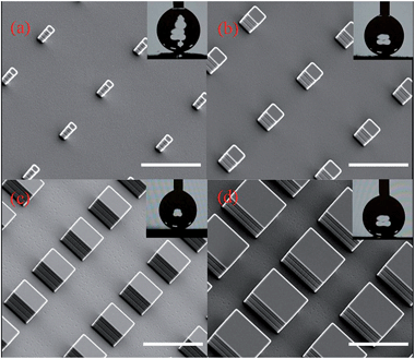 | ||
| Fig. 1 Scanning electron microscopy images of the micropillared superhydrophobic surfaces. The solid fraction varies from (a) 0.01, (b) 0.04, (c) 0.16 to (d) 0.36. All scale bars are 40 μm. | ||
From the observation of apparent contact angles measurements by the sessile drop method (Method section for details), the droplet boundary was fixed on the substrate in the initial stage and the contact radius of the droplet remained constant with increase of drop volume. This pinning mode was succeeded by a depinning mode once an increase of contact radius was observed. This pinning–depinning process was repeatedly observed on every sample, as sketched in Fig. 2. As expected, the existence of the droplet pinning phenomenon indicated that there existed a pinning force on the liquid/solid interface. This explained why many metastable droplet profiles were observed with different apparent contact angles on the same superhydrophobic sample. During this whole process, as the apparent contact angle increased, the driving force by surface tension opposing the pinning force per unit length of the apparent droplet boundary also got increased.22 Once the apparent contact angle reaches to the largest value (the advancing contact angle θa), the driving force overcame the pinning force and lead to the depinning motion of the droplet boundary observed. The driving force therefore can be expressed as
Fd = γ(cos![[thin space (1/6-em)]](https://www.rsc.org/images/entities/char_2009.gif) θc − cos θc − cos![[thin space (1/6-em)]](https://www.rsc.org/images/entities/char_2009.gif) θx) θx)
| (1) |
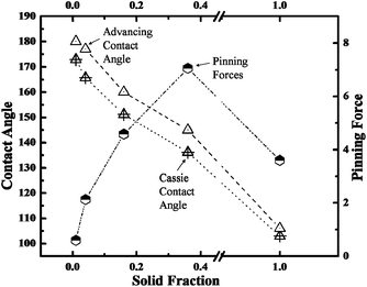
Fig. 3 shows the predicted Cassie contact angles and the measured advancing contact angles of water droplet, and also the calculated pinning forces by submitting θa to eqn (1), with respect to the liquid/solid contact area fraction. The results presented in Fig. 3 clearly indicated that the pinning force decreased with the liquid/solid contact area fraction on superhydrophobic surfaces. But S0.36 and S0.16 exhibited even greater pinning force than the one on hydrophobic smooth silicon surface. This result indicated that the patterned hydrophobic surfaces (i.e. low solid fraction) could cause a stronger pinning effect than a flat hydrophobic surface (i.e. unit solid fraction), and therefore, we believe that it is inappropriate to predict the pinning effect by simply using the parameter of liquid/solid contact area fraction. Coincidently, McCarthy supported that the role of TCL was much more important than liquid/solid contact area fraction in the pinning–depinning phenomena.18–20 However, McCarthy studied the static and apparent TCL instead of the dynamic and actual TCL. Therefore, they still could not explain exactly how TCL affects the pinning phenomena.
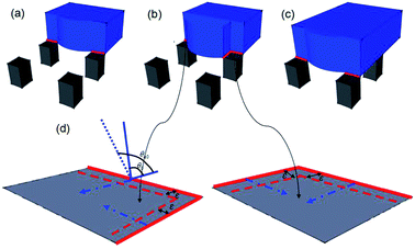
It is well-known that there are two interfaces, i.e. the liquid/solid interface and the liquid/air interface at the base of Cassie droplets.22 Fluid is able to slip smoothly on the liquid/air interface.23 Therefore, it can be concluded that the pinning force is caused by the liquid/solid interface. With this reasoning, let us describe the pinning–depinning process in Fig. 4. In our theory, once the droplet volume is increased to a certain value, the advancing boundary of the water droplet will depin from one row of pillars and quickly slip over the “air gap” between the pillars to the next row of pillars. During the initial contacting period, the LTCL occupies only one edge of the pillar due to the hydrophobic nature of the surface as indicated in red in Fig. 4(a). As the droplet volume increase, the discontinuous LTCL segments could not advance over the pillar surfaces immediately because of the local pinning force caused by the pillar edge, which is mainly induced by the inherent hysteresis of hydrophobic surface. Meanwhile, the boundary over the liquid/air interface advances freely to the spacing between pillars and gains new liquid/air interface underneath. During this stage, LTCL length is increased by elongation along the periphery of the pillars, which further increases the local pinning force on each pillar surface. This local pinning force increases until the spacing between the two adjacent pillars is totally replaced by the liquid/air interface, as indicated in Fig. 4(b). This local pinning effect makes both the local contact angle θL at the LTCL and therefore the local driving force by surface tension increase with the droplet volume. Once the LTCL length reaches the maximal value and θL increases to the local inherent advancing contact angle value θa0, the maximal local driving force will appeal the depinning motion on each of the pillar surface. This makes the droplet boundary advance outwards and then slip over the “air gap” once again to contact the next pillars row, as indicated in Fig. 4(c) and (d). Briefly, the inherent hysteresis on hydrophobic surface resists the aggression of LTCL segments during the initial fluid volume increasing stage. However, after the local contact angle has reached the local inherent advancing contact angle value on the hydrophobic surface and the LTCL length is increased to a certain value, the local driving force on each pillar would overcome the local pinning force and realize the depinning motion.
The theory deduced above provides us an explanation of pinning phenomena on superhydrophobic surfaces from micro-perspective. Actually, this theory can also be utilized to predict the advancing contact angle. Let's assume an infinitesimally small displacement ε of the LTCL along the vector direction (Fig. 4(d)), the associated free energy change on each pillar can be calculated as
dE = (γSV − γSL)Xε − γ![[thin space (1/6-em)]](https://www.rsc.org/images/entities/char_2009.gif) cos cos![[thin space (1/6-em)]](https://www.rsc.org/images/entities/char_2009.gif) θa0Xε θa0Xε
| (2) |
Fdm = dE/ε = (cos![[thin space (1/6-em)]](https://www.rsc.org/images/entities/char_2009.gif) θ0 − cos θ0 − cos![[thin space (1/6-em)]](https://www.rsc.org/images/entities/char_2009.gif) θa0)γX θa0)γX
| (3) |
 | (4) |
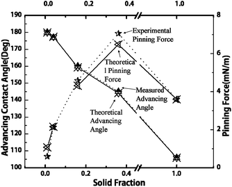 | ||
| Fig. 5 Comparisons between the theoretical and experimental values of the advancing contact angles and the pinning forces. Experimental pinning forces are the values calculated from the measured advancing contact angles, while the theoretical pinning forces are the values predicted from eqn (4). | ||
We have further extended this theory to explain the stickiness of different surfaces. Let us define a new parameter δ and name it as the normalized LTCL length.
 | (5) |
The pinning/driving force is then related to this parameter as
Fd = δγ(cos![[thin space (1/6-em)]](https://www.rsc.org/images/entities/char_2009.gif) θ0 − cos θ0 − cos![[thin space (1/6-em)]](https://www.rsc.org/images/entities/char_2009.gif) θa0) θa0)
| (6) |
eqn (6) indicates that the pinning/driving force applied on unit length could be directly predicted by the normalized TCL length δ. It is obviously that the value of δ equal to unit on a flat surface since there is no LTCL elongation. On the contrary, the value of δ could be larger than unit on some superhydrophobic surfaces, such as S0.36 and S0.16. Therefore, the pinning/driving force is reasonable stronger than that on a flat hydrophobic surface. Meanwhile, a lower pinning/driving force is expected on S0.04 and S0.01.
This new built theory not only well explained the results in Fig. 3, but also could be used to explain the stickiness on other superhydrophobic surfaces.15,16 We further extended the theory on the lotus leaf and rose petal, which represent the most famous examples of slippery and sticky superhydrophobic surfaces in nature, respectively. As only few nanoscale bumps over microstructure on lotus leaf is in contact with liquid, the LTCL elongation behavior is therefore well restricted. This results in a slippery surface according to our theory. In another case, the hierarchical micro- and nanostructures on the surface of rose petal make the liquid film impregnate into the gaps between microstructure, while holds a non-wetting state on nanostructure. The liquid film between microstructure makes the δ value on rose petal much greater than unit; the sticky performance also gets well explanation by using our model, and again proves the applicability of our new theory. Actually, our finding is not only of interest in theory, but also of great interest in some real application fields, especially in the field of microfluidics. Droplet pinning mechanism could be well used to deposit biofluids, and then get biomaterials arranged in order. Therefore, results of this work can be applied for making novel microfluidic chips which can be used for studying biochemical and biophysical problems.
By investigating the advancing contact angles and analyzing the LTCL elongation behavior on different square pillar arrays, we found that the pinning force at the droplet boundary was directly proportional to the maximal LTCL attainable, which depends on the surface morphology. This new insight was used to explain the sticky or slippery behavior on various surfaces. This pinning mechanism is also important for making novel microfluidics operating platform, which features drag reduction or adhesive functions.
Acknowledgements
This research was supported by the National Basic Research Program of China (2013CB328803; 2010CB327705); the National High Technology Research and Development Program of China (2012AA03A302; 2013AA011004); National Natural Science Foundation of China (61306140, 51202028); China Postdoctoral Science Foundation (2013M530222); Natural Science Foundation of Jiangsu Province (BK20130618); and Jiangsu Planned Projects for Postdoctoral Research Funds (1301097C).Notes and references
- W. Barthlott and C. Neinhuis, Planta, 1997, 202, 1–8 CrossRef CAS.
- L. Feng, Y. A. Zhang, J. M. Xi, Y. Zhu, N. Wang, F. Xia and L. Jiang, Langmuir, 2008, 24, 4114–4119 CrossRef CAS PubMed.
- N. Yi, B. Huang, L. N. Dong, X. J. Quan, F. J. Hong, P. Tao, C. Y. Song, W. Shang and T. Deng, Sci. Rep., 2014, 4, 4303 Search PubMed.
- X. Y. Jiang, Y. C. Wu, B. Su, R. G. Xie, W. S. Yang and L. Jiang, Small, 2014, 10, 258–264 CrossRef CAS PubMed.
- W. Da, S. J. Kim, W. K. Weong, S. H. Kim, K. R. Lee, H. Y. Kim and M. W. Moon, Sci. Rep., 2013, 3, 2524 Search PubMed.
- R. Furstner, W. Barthlott, C. Neinhuis and P. Walzel, Langmuir, 2005, 21, 956–961 CrossRef PubMed.
- J. P. Rothstein, Annu. Rev. Fluid Mech., 2010, 42, 89–109 CrossRef.
- K. K. Varanasi, T. Deng, J. D. Smith, M. Hsu and N. Bhate, Appl. Phys. Lett., 2010, 97, 234102 CrossRef PubMed.
- J. Genzer and K. Efimenko, Biofouling, 2006, 22, 339–360 CrossRef CAS PubMed.
- P. M. Barkhudarov, P. B. Shah, E. B. Watkins, D. A. Doshi, C. J. Brinker and J. Majewski, Corros. Sci., 2008, 50, 897–902 CrossRef CAS PubMed.
- X. Hong, X. Gao and L. Jiang, J. Am. Chem. Soc., 2007, 129, 1478–1479 CrossRef CAS PubMed.
- P. Calvert, Chem. Mater., 2001, 13, 3299–3305 CrossRef CAS.
- D. Ishii, H. Yabu and M. Shimomura, Biomedical Engineering Systems and Technologies, 2010, vol. 52, pp. 136–142 Search PubMed.
- C. W. Extrand, Langmuir, 2002, 18, 7991–7999 CrossRef CAS.
- G. McHale, N. J. Shirtcliffe and M. I. Newton, Langmuir, 2004, 20, 10146–10149 CrossRef CAS PubMed.
- N. J. Shirtcliffe, S. Aqil, C. Evans, G. McHale, M. Newton, C. C. Perry and P. Roach, J. Micromech. Microeng., 2004, 14, 1384–1389 CrossRef.
- M. Nosonovsky, Langmuir, 2007, 23, 9919–9920 CrossRef PubMed.
- L. Gao and T. J. McCarthy, Langmuir, 2006, 22, 6234–6237 CrossRef CAS PubMed.
- K. A. Wier and T. J. McCarthy, Langmuir, 2006, 22, 2433–2436 CrossRef CAS PubMed.
- D. Oner and T. J. McCarthy, Langmuir, 2000, 16, 7777–7782 CrossRef.
- A. B. D. Cassie and S. Baxter, Trans. Faraday Soc., 1944, 40, 546–551 RSC.
- K. Sefiane, J. Colloid Interface Sci., 2004, 272, 41 CrossRef PubMed.
- S. L. Ceccio, Annu. Rev. Fluid Mech., 2010, 42, 183–203 CrossRef.
- T. Young, Philos. Trans. R. Soc. London, 1805, 95, 65–87 CrossRef.
Footnote |
| † Electronic supplementary information (ESI) available: Experimental procedure. See DOI: 10.1039/c4ra06428c |
| This journal is © The Royal Society of Chemistry 2014 |

