In situ synthesis of a reduced graphene oxide/cuprous oxide nanocomposite: a reusable catalyst
Indranil Roya,
Amartya Bhattacharyyaa,
Gunjan Sarkara,
Nayan Ranjan Sahaa,
Dipak Ranab,
Partha Pratim Ghoshc,
Mainak Palitd,
Asish Ranjan Dasc and
Dipankar Chattopadhyay*a
aDepartment of Polymer Science and Technology, University of Calcutta, 92 A.P.C. Road, Kolkata 700009, India. E-mail: dipankar.chattopadhyay@gmail.com
bDepartment of Chemical and Biological Engineering, Industrial Membrane Research Institute, University of Ottawa, 161 Louis Pasteur St., ON K1N 6N5, Ottawa, Canada
cDepartment of Chemistry, University of Calcutta, 92 A.P.C. Road, Kolkata 700009, India
dCenter for Research in Nanoscience and Nanotechnology, University of Calcutta, Sector-III, Salt Lake City, Kolkata 700098, India
First published on 3rd October 2014
Abstract
A reduced graphene oxide/cuprous oxide (RGO/Cu2O) nanocomposite has been successfully synthesized applying a simple in situ reduction method using an aqueous solution of lactulose which is used simultaneously as a reducing and stabilizing agent. Lactulose, a disaccharide, has the ability to reduce both GO and CuSO4 in situ under alkaline conditions. The GO and RGO/Cu2O nanocomposites are characterized using transmission electron microscopy, energy dispersive X-ray spectroscopy, field emission scanning electron spectroscopy, X-ray diffraction, Fourier-transform infrared spectroscopy and UV-vis absorption spectroscopy. The surface charge as well as stability is established by analyzing the zeta potential value. The results confirm the synthesis of the RGO/Cu2O nanocomposite and the existence of interactions between Cu2O and RGO. It is also observed that Cu2O nanoparticles with an average size of 5 nm are uniformly dispersed throughout the RGO sheets. The catalytic activity of the RGO/Cu2O nanocomposite is excellent for the ‘click’ reaction and remains the same for six cycles.
1. Introduction
Graphene is a single layer of carbon atoms which are compactly packed in a hexagonal lattice forming a honeycomb like structure.1 It is the first 2D material with unique properties like high thermal conductivity (∼5 × 10³ W m−1 K−1),2 high mobility of charge carriers (2 × 106 cm2 V−1 s−1),3 high optical transmittance (∼97.7%),4 high Young's modulus values (∼10 TPa)5 and huge theoretical specific surface area (2.63 × 10³ m2 g−1).6 The combined effect of all these exclusive properties makes graphene a promising material for the fabrication of graphene based nanocomposites that have enormous application potential in various fields like supercapacitors,6 nanoelectronics,7,8 batteries,9 solar cells,10,11 fuel cells,12,13 electrocatalysis,14 sensing15,16 and nanocomposites.17,18Cuprous oxide (Cu2O), being a versatile semiconductor with a narrow band gap of 2.17 eV and having the suitable energy level position,19 can be a promising candidate in many application oriented fields like solar cells,20 lithium ion batteries,21 gas sensors,22 biosensors23 and magnetic storage devices.24 In comparison to conventional photocatalysts like TiO2 and ZnO, the utilization range of sunlight by cuprous oxide stretches to the visible light spectrum, which makes it a more suitable visible photocatalyst. Nevertheless, Cu2O is a lower toxic and lesser cost material, which makes it eco-friendly and suitable for large scale applications. There exist a range of Cu2O nanocrystals with various morphologies including cubes,23,25 nanospheres,26 pyramids,27,28 octahedrons29 and squares.30,31
Nanotechnology offers us the opportunity to make products and processes green from the beginning.32–34 The development of green processes and pollutant free catalysts has integrated great importance. Catalysis lies at the heart of innumerable chemical protocols. Pioneering catalytic processes based on such nano catalysts35,36 will be simpler, more economically efficient and more eco-friendly instituting “green chemistry” that produces only the most desirable products. In the case of graphene based metal or metal oxide nanocomposites, the loading of metal or metal oxide nanoparticles such as Au,37–40 Ag,41–43 Pt,13,42,44,45 Pd,46,47 Sn,42,48 Co,49 TiO2,50 MnO2, SnO2 and ZnO,51,52 into the graphene matrix gives birth to a new hybrid material. This significantly enhances the ability of this new hybrid material to apply it's supreme application potential towards super-capacitor applications,51,52 electrocatalysts,53,54 lithium ion batteries,55 surface-enhanced Raman scattering applications56 and catalysis.46,57 Recently, graphene–copper or graphene–copper oxide nanocomposites have shown new promise in applications including catalysis, gas sensor, lithium ion battery, field effect transistor, biosensor and medical applications. Considering the intrinsic properties of both Cu2O and graphene, graphene–Cu2O composites are expected to exhibit enhanced or even novel properties including improved charge–discharge capacity and enhanced electrochemical activity.58
In this circumstance, we have successfully derived a simple protocol to fabricate reduced graphene oxide/cuprous oxide (RGO/Cu2O) nanocomposite at high temperature and high pressure using lactulose as a reducing cum stabilizing agent. Lactulose,59 being a disaccharide of galactose and fructose, is considered to be an effective candidate for green synthesis as it is non-toxic and environmentally friendly. In this article, we discuss the study of the morphology of RGO/Cu2O nanocomposites. The surface electrical potential energy of the composite is examined by measuring zeta potential. Our main objective is to develop a recyclable catalyst for ecological concerns based on RGO/Cu2O for ‘click’ reaction, as ‘click’ chemistry is clearly on the rise. It offers an almost unlimited array of inert triazole-containing architectures resulting from Huisgen [3 + 2] cycloadditions,60 particularly between high-energy organic azides and terminal alkynes.
2. Experimental
Materials
Graphite powder and lactulose were obtained from Sigma-Aldrich Inc. Concentrated sulfuric acid (98% H2SO4, GR grade), potassium permanganate (KMnO4, purified) and hydrogen peroxide solution (30% H2O2), sodium nitrate (NaNO3, extra pure), copper sulphate (CuSO4, extra pure) and sodium hydroxide (NaOH purified) were received from Merck Specialties Pvt. Ltd.Preparation of GO
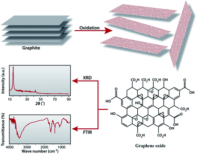
The graphene oxide (GO) was synthesized from natural graphite powder by a modified Hummers method.61 Graphite powder (1 g) and NaNO3 (1 g) were added into 50 ml of 98% concentrated H2SO4 under vigorous stirring conditions in a 250 ml conical flask placed in an ice bath. After a few moments, the whole mass was converted to black slurry. Then, KMnO4 (6 g) was added slowly into the slurry while maintaining the reaction temperature below 20 °C. After 4 h, the whole system was taken out of the ice bath and diluted with 100 ml water and then stirred for 2 h at ambient temperature. To control the pH of the reaction medium and also to terminate the reaction, 200 ml of hot water followed by 20 ml H2O2 were added to the above reaction mixture. The resultant mixture was washed several times with distilled water and the residue was subjected to centrifuge to get the pure graphene oxide powder. The GO sample was collected and dried at 60 °C for 24 h Fig. 1 illustrates the experimental steps of preparation and characterization of GO.Preparation RGO/Cu2O nanocomposite
The stipulated amount (80 mg) of GO was dispersed into a definite amount (30 ml) of distilled water by ultrasonication for 2 h to form a GO dispersion. An aqueous solution of CuSO4 (80 mg CuSO4 in 10 ml distilled water) was added to the dispersion and stirred for 2 h to get a suspension to which the required amount of NaOH solution was added to adjust the pH (>10) of the resultant solution. Finally, an aqueous solution of lactulose (10 wt%) was added into the mixture and sonicated for 10 minutes in a sealed 100 ml conical flask. The total volume of the solution in the conical was 50 ml. The conical was sealed with non-absorbent cotton and placed in a normal pressure cooker for 1 h at 120 °C temperature and at a pressure of 15 psi to bring about the formation of the RGO/Cu2O nanocomposite.Characterization
The morphology of the synthesized sample was characterized using a transmission electron microscope (TEM-JEOL-JEM-2100 with a 200 kV accelerating voltage) and field emission scanning electron microscopy (FESEM-ZEISS Auriga instrument). Samples for TEM analysis were prepared by drying a droplet of material suspension on a carbon coated copper grid. FESEM samples were prepared by drying a droplet of the suspension on a silicon substrate coated with gold in the sputters coater. X-ray diffraction (XRD) patterns were recorded on an X-PERT-PRO Panalytical diffractometer using Cu Kα (λ = 1.5406) as the X-ray source at a scanning rate of 1° min−1 and a generator voltage of 40 kV and a current of 30 mA. The Fourier transform infrared (FTIR) spectroscopic experiments were performed with a Bruker-Optics Alpha-T spectrophotometer over the range of 400 to 4000 cm−1. UV-Vis absorption spectra of the prepared materials were recorded in a Perkin Elmer Lambda 25 by dispersing composite material in distilled water. Zeta-potential measurements were performed using a Zetasizer Nano-ZS90 System (Malvern Inc.). Thermogravimetric analysis was carried out using a Shimadzu TGA-50 thermal analyser.3. Results and discussion
Formation mechanism of RGO/Cu2O nanocomposite
A facile in situ reduction process is introduced to prepare the RGO/Cu2O nanocomposite in which both the formation of Cu2O nanoparticles and the reduction of GO are achieved in one-pot reaction. Fig. 2 illustrates the mechanism of formation and characterization of the RGO/Cu2O nanocomposite. It is reported that the exteriors of the chemically exfoliated GO sheets are wrapped up by a large number of hydroxyl, carboxyl and epoxy groups which are brought in on GO sheets during oxidation.62 These functional groups are actually responsible for the tie up of Cu(OH)2 crystals on to GO sheets which enables the subsequent in situ formation of nanoparticles and the simultaneous reduction to RGO using lactulose in the reaction medium. After the mixing of the GO suspension and CuSO4 solution, Cu+2 ions are adsorbed onto the GO surfaces due to the bonding with the oxygen atoms of the negatively charged oxygen containing functional groups via electrostatic forces.63 The addition of NaOH not only increases the pH of the reaction medium but also helps to generate Cu(OH)2 crystals which act as precursors for Cu2O nanoparticles. These Cu(OH)2 crystals tie up with the functional groups of GO via intermolecular hydrogen bonding or coordination bonds. Finally, lactulose reduces the Cu(OH)2 to produce Cu2O nanoparticles. Meanwhile, RGO sheets are formed through the reduction of GO [eqn (1)]. Thus, the RGO/Cu2O nanocomposite is obtained by the reduction reactions carried out in one step with high pressure and high temperature in a pressure cooker using lactulose.| Cu(OH)2 + GO + lactulose → RGO/Cu2O | (1) |
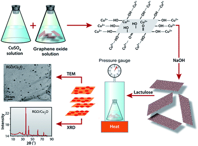 | ||
| Fig. 2 Scheme illustrating the mechanism of formation and characterization of RGO/Cu2O nanocomposite. | ||
Transmission electron microscopy
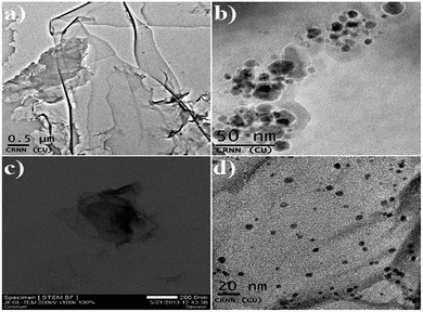
TEM images of RGO, Cu2O nanoparticles and the RGO/Cu2O nanocomposite are recorded and shown in Fig. 3. Fig. 3a shows RGO sheets with a typical rippled and crumpled morphology in which the nanosheet contains many wrinkles throughout the surface. This clearly shows that the interlayer becomes loose and the interlayer distance becomes broader. Cu2O nanoparticles generally reveal a spherical morphology of particle size in the range of 10 nm as shown in Fig. 3b. It is quite predictable that a few smaller nanoparticles agglomerate into comparatively larger secondary particles probably due to the extremely small dimension and high surface energy of the primary particles. From the TEM images of RGO/Cu2O nanocomposite shown in Fig. 3c and d, it is evident that the deposition of Cu2O nanoparticles onto the reduced graphene nanosheet is homogeneous without any apparent aggregation. The average particle size of Cu2O nanoparticles is 5 nm in the RGO/Cu2O nanocomposite which is slightly smaller than the pure Cu2O nanoparticles. The Cu2O nanoparticles are strongly anchored on the surface of the RGO sheets. Such interactions accompanied with good mechanical flexibility of the RGO sheets prevent the agglomeration of nanoparticles to larger particles. The highly dispersed nanoparticles anchored on the large surface area, and possessed excellent properties with advantageous application for catalytic activity.64Energy dispersive X-ray (EDX) analysis
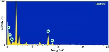
Fig. 4 depicts the EDX of the RGO/Cu2O nanocomposite. It is apparent from the spectrum that the synthesized nanocomposite contains no impurities and it clearly reveals the sufficient crystallinity of Cu2O nanoparticles. EDX also confirms that RGO/Cu2O nanocomposite is successfully prepared and the sample contains ingredients of copper and oxygen and exhibits an oxide state.Field emission scanning electron microscopy
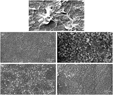
Fig. 5 illustrates FESEM images of RGO, Cu2O and RGO/Cu2O nanocomposite. As observed from Fig. 5a, the RGO sheet presents crumpled surface textures with curling edges. It is quite evident that the surface morphology of the nanocomposite is fairly different from both the RGO and Cu2O nanoparticles. Fig. 5b and c shows the FESEM images of Cu2O nanoparticles. The images reveal a spherical morphology and some of those particles agglomerate into large particles to reduce their surface energy. This is evident from the FESEM image of higher magnification (Fig. 5c). It can be seen from the FESEM images of the composite (Fig. 5d and e) that Cu2O nanoparticles are well dispersed and scattered throughout the RGO matrix with the formation of an interconnected hybrid network.X-ray diffraction (XRD)
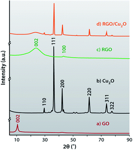
The X-ray diffraction patterns of the GO, RGO, Cu2O and RGO/Cu2O nanocomposite are shown in Fig. 6. In this figure, GO portrays the characteristic reflection peak at 10.7° (002) corresponding to an inter-planar spacing of 0.84 nm. On the contrary, the interlayer distance for the (002) peak of graphite is at 0.337 nm (2θ = 26.3°). It is quite predictable that the incorporation of oxygenated functional groups like epoxy, hydroxyl (–OH), carboxyl (–COOH) and carbonyl (–C![[double bond, length as m-dash]](https://www.rsc.org/images/entities/char_e001.gif) O) groups in the graphite enlarges its interlayer spacing and also acts as anchoring sites for metal oxides. It can be observed that the disappearance of the characteristic peak of GO at 10.7° demonstrates the efficient and complete reduction of GO to RGO by the lactulose solution during the redox reaction when Cu2O nanoparticles are generated. Cu2O shows sharp peaks at a 2θ value of 29.6° (110), 36.3° (111), 42.4° (200), 61.5° (220), 73.6° (311) and 77.5° (322) which confirms the formation of a cubic crystal of Cu2O consistent with the standard XRD data. (JCPDS no. 05-0667)65,66 X-ray diffraction of RGO shows two reflection peaks at 24.1° (002) and 43.1° (100) which are much weaker in the composite and this suggests disordered stacking and less agglomeration of the RGO sheets in composites. The sharp and intense diffraction peaks of Cu2O explains the crystalline nature of the metal oxide nanoparticles and a weak diffraction peak at 22.5° for GO results from the removal of surface oxy-functional groups and the restacking of reduced GO sheets during the drying process of GO.67 Finally, Fig. 6d shows no peak for Cu, CuSO4 and GO which indicates complete conversion of CuSO4 to Cu2O and GO to RGO using lactulose. Therefore, it can be concluded that lactulose is an excellent reducing agent for the synthesis of RGO/Cu2O nanocomposite.
O) groups in the graphite enlarges its interlayer spacing and also acts as anchoring sites for metal oxides. It can be observed that the disappearance of the characteristic peak of GO at 10.7° demonstrates the efficient and complete reduction of GO to RGO by the lactulose solution during the redox reaction when Cu2O nanoparticles are generated. Cu2O shows sharp peaks at a 2θ value of 29.6° (110), 36.3° (111), 42.4° (200), 61.5° (220), 73.6° (311) and 77.5° (322) which confirms the formation of a cubic crystal of Cu2O consistent with the standard XRD data. (JCPDS no. 05-0667)65,66 X-ray diffraction of RGO shows two reflection peaks at 24.1° (002) and 43.1° (100) which are much weaker in the composite and this suggests disordered stacking and less agglomeration of the RGO sheets in composites. The sharp and intense diffraction peaks of Cu2O explains the crystalline nature of the metal oxide nanoparticles and a weak diffraction peak at 22.5° for GO results from the removal of surface oxy-functional groups and the restacking of reduced GO sheets during the drying process of GO.67 Finally, Fig. 6d shows no peak for Cu, CuSO4 and GO which indicates complete conversion of CuSO4 to Cu2O and GO to RGO using lactulose. Therefore, it can be concluded that lactulose is an excellent reducing agent for the synthesis of RGO/Cu2O nanocomposite.
Fourier-transform infrared (FTIR) spectroscopy
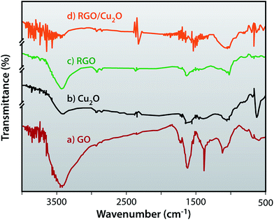
FTIR provides structural information confirming the successful reduction of GO to RGO and the formation of the RGO/Cu2O nanocomposite in the presence of lactulose. The FTIR spectra of GO, Cu2O, RGO and RGO/Cu2O nanocomposites are depicted in Fig. 7. As shown in Fig. 7a, the strong band at around 3427 cm−1 is caused by the stretching vibration of O–H while the peak at 1383 cm−1 corresponds to the deformation of the O–H group. The band at 1720 cm−1 reflects the C![[double bond, length as m-dash]](https://www.rsc.org/images/entities/char_e001.gif) O vibration of the –COOH group present at the edge of the graphene oxide. This peak, that has disappeared in the spectrum of RGO, indicates the efficient reduction of GO by lactulose and the band at 1627 cm−1 is assigned to the contribution from the skeletal vibrations of epoxide groups and graphitic domains. The intensity of the peaks at 2924 cm−1 and 2854 cm−1 become more prominent in the case of RGO as evident from Fig. 7b. Fig. 7c represents the FTIR spectra of Cu2O which shows a sharp peak at 625 cm−1 which is attributed to Cu–O vibration whereas two other peaks at 3430 cm−1 and 1615 cm−1 belong to the stretching and bending vibration of hydroxyl groups, respectively of the absorbed water. For the RGO/Cu2O nanocomposite, the Cu–O vibration peak at 625 cm−1 shifts to 604 cm−1 and the peak for C
O vibration of the –COOH group present at the edge of the graphene oxide. This peak, that has disappeared in the spectrum of RGO, indicates the efficient reduction of GO by lactulose and the band at 1627 cm−1 is assigned to the contribution from the skeletal vibrations of epoxide groups and graphitic domains. The intensity of the peaks at 2924 cm−1 and 2854 cm−1 become more prominent in the case of RGO as evident from Fig. 7b. Fig. 7c represents the FTIR spectra of Cu2O which shows a sharp peak at 625 cm−1 which is attributed to Cu–O vibration whereas two other peaks at 3430 cm−1 and 1615 cm−1 belong to the stretching and bending vibration of hydroxyl groups, respectively of the absorbed water. For the RGO/Cu2O nanocomposite, the Cu–O vibration peak at 625 cm−1 shifts to 604 cm−1 and the peak for C![[double bond, length as m-dash]](https://www.rsc.org/images/entities/char_e001.gif) C vibration at 1589 cm−1 is blue-shifted to 1551 cm−1 suggesting the successful formation of the RGO/Cu2O nanocomposite.
C vibration at 1589 cm−1 is blue-shifted to 1551 cm−1 suggesting the successful formation of the RGO/Cu2O nanocomposite.
UV-vis absorption spectra
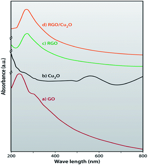
In order to optically analyse the synthesized RGO/Cu2O nanocomposite, UV-VIS absorption spectra of GO, RGO, Cu2O and RGO/Cu2O nanocomposite are recorded and depicted in Fig. 8. Fig. 8a shows a sharp absorption maxima at 242 nm for GO demonstrating π–π* transition of aromatic C![[double bond, length as m-dash]](https://www.rsc.org/images/entities/char_e001.gif) C bonds68 and a broad peak at 304 nm indicates n–π* transition for C
C bonds68 and a broad peak at 304 nm indicates n–π* transition for C![[double bond, length as m-dash]](https://www.rsc.org/images/entities/char_e001.gif) O respectively. As evident from Fig. 8b, the peak at 242 nm of GO shifted to the higher wavelength (269 nm in the case of the RGO) verifying the complete reduction of GO by the lactulose solution.69 A broad absorption band located at 550 nm attributes the formation of cubic crystals of Cu2O to the chemical reaction between the CuSO4 and lactulose solution.70 The formation of the nanocomposite is indicated by the red shift of the RGO peak at 269 nm to 271 nm, verifying the fact that nanoparticles of Cu2O have adhered to the surface of the RGO sheets.
O respectively. As evident from Fig. 8b, the peak at 242 nm of GO shifted to the higher wavelength (269 nm in the case of the RGO) verifying the complete reduction of GO by the lactulose solution.69 A broad absorption band located at 550 nm attributes the formation of cubic crystals of Cu2O to the chemical reaction between the CuSO4 and lactulose solution.70 The formation of the nanocomposite is indicated by the red shift of the RGO peak at 269 nm to 271 nm, verifying the fact that nanoparticles of Cu2O have adhered to the surface of the RGO sheets.
Dynamic light scattering
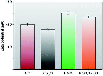
The zeta potential of GO, RGO, Cu2O and RGO/Cu2O nanocomposite in aqueous solution is measured in a dynamic light scattering instrument to observe the amount of stability (Fig. 9). The GO shows an average zeta potential value of −19.9 ± 0.53 mV explaining the existence of a sufficient amount of negative charge density arising from the carboxylic groups present in the GO. The reduction of GO with lactulose produces RGO with a negative charge density comparatively lower than that of GO which extracts a zeta potential value of −25.2 ± 0.47 mV. Meanwhile, Cu2O, obtained by the reduction of copper sulphate by lactulose, gives a little higher zeta potential value of −17.8 mV. Naturally, the synthesized RGO/Cu2O nanocomposite exhibits a zeta potential of −23.4 mV which lies in between the zeta potential value of the RGO and Cu2O nanoparticles. This suggests the interaction between RGO and Cu2O, which is in good agreement with the results of the FTIR and UV-vis spectroscopy results.Thermogravimetric analysis
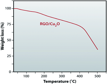
Thermal stability of RGO/Cu2O nanocomposite has been investigated before using the nanocomposite as catalyst for chemical reaction. Fig. 10 shows the thermogravimetric analysis of the RGO/Cu2O nanocomposite. It is clear from Fig. 10, that up to 50 °C there is no weight loss and 0.2–1% weight loss is taking place in between 50 °C to 60 °C due to the removal of H2O. About 10% weight loss is observed between 60 °C to 200 °C. So, our effort was directe2d to explore the catalytic activity of RGO/Cu2O nanocomposite bellow 60 °C and became successful as the composite offered marked stability.Catalytic activity
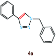
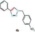
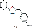
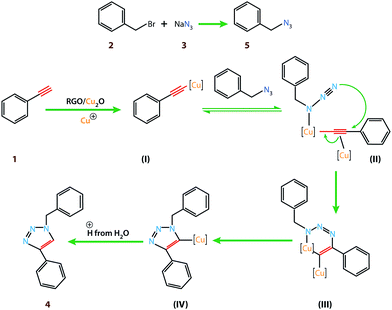
Copper(I) species has started receiving attention as effective and inexpensive catalysts for bringing about the click reaction71,72 which has prompted us to explore such catalytic properties in the case of RGO/Cu2O nanocomposite. The catalytic activity has been examined for the azide–alkyne cycloaddition popularly known as “click reaction”, and turns out to be one of the most important reactions for the preparation of 1,2,3-triazoles. This important reaction has found a wide range of applications in organic synthesis as well as bio- and medicinal chemistry and materials science. Typically, a mixture of phenyl acetylene (1.1 mmol), benzyl bromide (1.0 mmol), sodium azide (2.0 mmol) and 20 mg RGO/Cu2O in 4 ml water was stirred at 55 °C for 2 h, which afforded 1,2,3-triazoles with excellent yields (95%) as presented in Scheme 1. Generally the isolated yields were comparable, ranging from 91% to 95%, in the synthesis of triazole for three different substrates (Table 1).To estimate the scope and generality of the protocol, we have chosen three different benzyl bromide derivatives, one unsubstituted benzyl bromide and two substituted benzyl bromide containing an electron-withdrawing and electron donating groups with phenyl acetylene and sodium azide under optimized reaction conditions to check the viability of the click reaction protocol and eventually achieved the corresponding 1,2,3-triazoles and the results are presented in Table 1. As mentioned in Table 1, the reaction proceeded smoothly with unsubstituted benzyl bromide, electron-withdrawing and also with electron-releasing para-substituted benzyl bromide with equal ease.
With this outstanding result in hand, we are now in a position to propose the mechanistic interpretation of high catalytic activity of RGO/Cu2O specifically in aqueous media (Scheme 2). Initially, benzyl bromide reacted with sodium azide to generate the benzyl azide (5). Additionally, the RGO/Cu2O catalyst containing Cu+ ion which reacted with phenyl acetylene to form a pi complex (I). One copper atom is bonded to the acetylide while the other Cu atom serves to activate the azide (II). The metal center coordinates with the electrons on the nitrogen atom. The azide displaces one ligand to generate a copper–azide–acetylide complex (III). At this point [3 + 2] cyclo-addition reaction occurs followed by protonation; the source of proton being the hydrogen which was pulled off from the water (H2O) and finally formed the desired product (4).
General procedure for the synthesis of 1,4-disubstituted 1,2,3-triazoles
Alkyne (1.1 mmol), alkyl halide (1.0 mmol), sodium azide (2.0 mmol), H2O (4 ml) and RGO/Cu2O (20 mg) were placed in a reactor. The mixture was then stirred at 55 °C until the reaction showed its completion as judged by TLC (after elusion, the silica gel precoated aluminium plates were observed under UV light and charred in an alkaline KMnO4 solution). Then, the reaction mixture was treated with ethyl acetate and the resultant mixture was filtered to recover the RGO/Cu2O catalyst. The catalyst was then washed with water and ethanol and finally dried to obtain the recovered catalyst ready for reuse. The water layer was extracted with ethyl acetate (3 into 10 ml). The combined organic layer was washed with brine, dried over anhydrous Na2SO4 and concentrated in vacuo. The residue was then purified by recrystallization from ethanol so as to get the pure product.Reusability of catalyst
It is important to emphasize that catalyst recyclability is an important feature from a cost point of view. The catalyst could be recycled easily, followed by washing with ethanol several times to remove all the organic substances. It is then dried at room temperature and is recycled six consecutive times, resulting in almost unaltered catalytic activity. The recyclability chart for the catalytic potential of the RGO/Cu2O is shown in Fig. 11a (recovery amount of 90% and a yield of 88% after the 6th run). The TEM, EDX and FESEM images of recovered RGO/Cu2O after the 6th cycle are presented in Fig. 11b–d.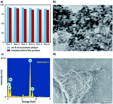 | ||
| Fig. 11 (a) Recyclability chart of RGO/Cu2O, (b) TEM image of reused RGO/Cu2O, (c) EDX image of reused RGO/Cu2O and (d) FESEM image of reused RGO/Cu2O. | ||
4. Conclusion
The RGO/Cu2O nanocomposite was successfully prepared by the in situ reduction process without using any hazardous chemicals. Cu2O nanoparticles, with an average size of 5 nm, were well dispersed and well scattered on the graphene sheet. The graphene sheet provides a large surface area to accommodate Cu2O nanoparticles, which prevent the restacking of RGO sheets. The RGO/Cu2O nanocomposite showed a remarkably enhanced catalytic activity in click reaction. After recycling six consecutive times, the RGO/Cu2O nanocomposite showed almost unaltered catalytic activity. Moreover, it has shown good thermal stability and reproducibility.Acknowledgements
The author I. Roy gratefully acknowledges the Technical Education Quality Improvement Programme, University of Calcutta for providing fellowship. A. Bhattacharyya likes to thank the Technical Education Quality Improvement Programme, University of Calcutta for his fellowship. G. Sarkar likes to thank Rajib Gandhi National fellowship, UGC, Government of India. N. R. Saha likes to thank UGC, Government of India for his fellowship. B. Bhowmick, Md. M. R. Mollick, D. Mondal, D. Maity and N. K. Bera of the University of Calcutta and S. Pattanayak of the West Bengal State University are acknowledged for their help. We acknowledge the CRNN, University of Calcutta for instrumental facilities.Notes and references
- A. K. Geim and K. S. Novoselov, Nat. Mater., 2007, 6, 183–191 CrossRef CAS PubMed.
- A. A. Balandin, S. Ghosh, W. Bao, I. Calizo, D. Teweldebrhan, F. Miao and C. N. Lau, Nano Lett., 2008, 8, 902–907 CrossRef CAS PubMed.
- K. I. Bolotin, K. J. Sikes, Z. Jiang, M. Klima, G. Fudenberg, J. Hone, P. Kim and H. L. Stormer, Solid State Commun., 2008, 146, 351–355 CrossRef CAS PubMed.
- R. R. Nair, P. Blake, A. N. Grigorenko, K. S. Novoselov, T. J. Booth, T. Stauber, N. M. R. Peres and A. K. Geim, Science, 2008, 320, 1308 CrossRef CAS PubMed.
- C. Lee, X. Wei, J. W. Kysar and J. Hone, Science, 2008, 321, 385–388 CrossRef CAS PubMed.
- M. D. Stoller, S. Park, Y. Zhu, J. An and R. S. Ruoff, Nano Lett., 2008, 8, 3498–3502 CrossRef CAS PubMed.
- P. Avouris, Z. Chen and V. Perebeinos, Nat. Nanotechnol., 2007, 2, 605–615 CrossRef CAS PubMed.
- Y. W. Son, M. L. Cohen and S. G. Louie, Nature, 2006, 444, 347–349 CrossRef CAS PubMed.
- P. Guo, H. Song and X. Chen, Electrochem. Commun., 2009, 11, 1320–1324 CrossRef CAS PubMed.
- X. Wang, L. Zhi, N. Tsao, Ž. Tomović, J. Li and K. Müllen, Angew. Chem., Int. Ed., 2008, 47, 2990–2992 CrossRef CAS PubMed.
- J. Wu, H. A. Becerril, Z. Bao, Z. Liu, Y. Chen and P. Peumans, Appl. Phys. Lett., 2008, 92, 263302 CrossRef PubMed.
- E. Yoo, T. Okata, T. Akita, M. Kohyama, J. Nakamura and I. Honma, Nano Lett., 2009, 9, 2255–2259 CrossRef CAS PubMed.
- Y. Si and E. T. Samulski, Chem. Mater., 2008, 20, 6792–6797 CrossRef CAS.
- L. Tang, Y. Wang, Y. Li, H. Feng, J. Lu and J. Li, Adv. Funct. Mater., 2009, 19, 2782–2789 CrossRef CAS.
- C. Shan, H. Yang, J. Song, D. Han, A. Ivaska and L. Niu, Anal. Chem., 2009, 81, 2378–2382 CrossRef CAS PubMed.
- Y. Wang, Y. Li, L. Tang, J. Lu and J. Li, Electrochem. Commun., 2009, 11, 889–892 CrossRef CAS PubMed.
- S. Stankovich, D. A. Dikin, G. H. B. Dommett, K. M. Kohlhaas, E. J. Zimney, E. A. Stach, R. D. Piner, S. T. Nguyen and R. S. Ruoff, Nature, 2006, 442, 282–286 CrossRef CAS PubMed.
- S. Guo, S. Dong and E. Wang, ACS Nano, 2009, 4, 547–555 CrossRef PubMed.
- L. Huang, F. Peng, H. Yu and H. Wang, Solid State Sci., 2009, 11, 129–138 CrossRef CAS PubMed.
- R. N. Brsikman, Sol. Energy Mater. Sol. Cells, 1992, 27, 361–368 CrossRef.
- P. Poizot, S. Laruelle, S. Grugeon, L. Dupont and J.-M. Taracon, Nature, 2000, 407, 496–499 CrossRef CAS PubMed.
- J. Zhang, J. Liu, Q. Peng, X. Wang and Y. Li, Chem. Mater., 2006, 18, 867–871 CrossRef CAS.
- T. Zhu, J. Wang and G. Xu, Cryst. Growth Des., 2009, 9, 633–638 Search PubMed.
- Z. C. Orel, A. Anžlovar, G. Dražić and M. Žigon, Cryst. Growth Des., 2007, 7, 453–458 CAS.
- X. Li, H. Gao, C. J. Murphy and L. Gou, Nano Lett., 2004, 4, 1903–1907 CrossRef CAS.
- D. P. Singh, N. R. Neti, A. S. K. Sinha and O. N. Srivastava, J. Phys. Chem. C, 2007, 111, 1638–1645 CAS.
- S. Ding, J. S. Chen, G. Qi, X. Duan, Z. Wang, E. P. Giannelis, L. A. Archer and X. W. Lou, J. Am. Chem. Soc., 2011, 133, 21–23 CrossRef CAS PubMed.
- R. Liu, F. Oba, E. W. Bohannan, F. Ernst and J. A. Switzer, Chem. Mater., 2003, 15, 4882–4885 CrossRef CAS.
- C. H. B. Ng and W. Y. Fan, J. Phys. Chem. B, 2006, 110, 20801–20807 CrossRef CAS PubMed.
- Q. Zhang, W. Li, C. Moran, J. Zeng, J. Y. Chen, L.-P. Wen and Y. Xia, J. Am. Chem. Soc., 2010, 132, 11372–11378 CrossRef CAS PubMed.
- K. X. Yao, X. M. Yin, T. H. Wang and H. C. Zeng, J. Am. Chem. Soc., 2010, 132, 6131–6144 CrossRef CAS PubMed.
- H. S. Sun, Y. F. Shi, P. Zhang, C. Zheng, X. Y. Zheng, F. Zhang, Y. Zhang, N. Guan, D. Zhao and G. D. Stucky, J. Am. Chem. Soc., 2011, 133, 14542–14545 CrossRef PubMed.
- H. Wang, H. Y. Jeong, M. Imura, L. Wang, L. Radhakrishnan, N. Fujita, T. Castle, O. Terasaki and Y. Yamauchi, J. Am. Chem. Soc., 2011, 133, 14526–14529 CrossRef CAS PubMed.
- A. Takai, Y. Doi, Y. Yamauchi and K. Kuroda, J. Phys. Chem. C, 2010, 114, 7586–7593 CAS.
- P. P. Ghosh and A. R. Das, J. Org. Chem., 2013, 78, 6170–6181 CrossRef CAS PubMed.
- P. P. Ghosh and A. R. Das, Tetrahedron Lett., 2012, 53, 140–143 Search PubMed.
- R. Muszynski, B. Seger and P. V. Kamat, J. Phys. Chem. C, 2008, 112, 5263–5266 CAS.
- G. Goncalves, P. A. A. P. Marques, C. M. Granadeiro, H. I. S. Nogueira, M. K. Singh and J. Grácio, Chem. Mater., 2009, 21, 4796–4802 CrossRef CAS.
- X. Huang, S. Li, Y. Huang, S. Wu, X. Zhou, S. Li, C. L. Gan, F. Boey, C. A. Mirkin and H. Zhang, Nat. Commun., 2011, 2, 292 CrossRef PubMed.
- B.-S. Kong, J. Geng and H.-T. Jung, Chem. Commun., 2009, 2174–2176 RSC.
- R. Pasricha, S. Gupta and A. K. Srivastava, Small, 2009, 5, 2253–2259 CrossRef CAS PubMed.
- S. Bai, X. Shen, G. Zhu, Z. Xu and Y. Liu, Carbon, 2011, 49, 4563–4570 CrossRef CAS PubMed.
- J. Li and C. Liu, Eur. J. Inorg. Chem., 2010, 2010, 1244–1248 CrossRef.
- S. Zhang, Y. Shao, H. Liao, M. H. Engelhard, G. Yin and Y. Lin, ACS Nano, 2011, 5, 1785–1791 CrossRef CAS PubMed.
- B. Seger and P. V. Kamat, J. Phys. Chem. C, 2009, 113, 7990–7995 CAS.
- G. M. Scheuermann, L. Rumi, P. Steurer, W. Bannwarth and R. Mülhaupt, J. Am. Chem. Soc., 2009, 131, 8262–8270 CrossRef CAS PubMed.
- N. Li, Z. Wang, K. Zhao, Z. Shi, S. Xu and Z. Gu, J. Nanosci. Nanotechnol., 2010, 10, 6748–6751 CrossRef CAS PubMed.
- X. Bin, J. Chen, H. Cao, L. Chen and J. Yuan, J. Phys. Chem. Solids, 2009, 70, 1–7 CrossRef CAS PubMed.
- J. H. Warner, M. H. Ruemmeli, A. Bachmatiuk, M. Wilson and B. Büchner, ACS Nano, 2010, 4, 470–476 CrossRef CAS PubMed.
- D. Wang, D. Choi, J. Li, Z. Yang, Z. Nie, R. Kou, D. Hu, C. Wang, L. V. Saraf, J. Zhang, I. A. Aksay and J. Liu, ACS Nano, 2009, 3, 907–914 CrossRef CAS PubMed.
- S. Chen, J. Zhu, X. Wu, Q. Han and X. Wang, ACS Nano, 2009, 4, 2822–2830 CrossRef PubMed.
- S. M. Paek, E. Yoo and I. Honma, Nano Lett., 2009, 9, 72–75 CrossRef CAS PubMed.
- Y. Qian, S. Lu and F. Gao, Mater. Lett., 2011, 65, 56–58 CrossRef CAS PubMed.
- S. Wang, S. P. Jiang and X. Wang, Electrochim. Acta, 2011, 56, 3338–3344 CrossRef CAS PubMed.
- Y. J. Mai, X. L. Wang, J. Y. Xiang, Y. Q. Qiao, D. Zhang, C. D. Gu and J. P. Tu, Electrochim. Acta, 2011, 56, 2306–2311 CrossRef CAS PubMed.
- X. Zhou, X. Huang, X. Qi, S. Wu, C. Xue, F. Y. C. Boey, Q. Yan, P. Chen and H. Zhang, J. Phys. Chem. C, 2009, 113, 10842–10846 CAS.
- A. R. Siamaki, A. E. R. S.Khder, V. Abdelsayed, M. S. El-Shall and B. F. Gupton, J. Catal., 2011, 279, 1–11 CrossRef CAS PubMed.
- C. Xu, X. Wang, L. Yang and Y. Wu, J. Solid State Chem., 2009, 182, 2486–9240 CrossRef CAS PubMed.
- M. M. R. Mollick, B. Bhowmick, D. Maity, D. Mondal, I. Roy, J. Sarkar, D. Rana, K. Acharya, S. Chattopadhyay and D. Chattopadhyay, Microfluid. Nanofluid., 2013, 16, 541–551 CrossRef.
- R. Huisgen, 1,3-Dipolar Cycloaddition Chemistry, ed. A. Padwa, Wiley, New York, NY, 1984, vol. 1, pp. 1–176 Search PubMed.
- W. S. Hummers and R. E. Offeman, J. Am. Chem. Soc., 1958, 80, 1339 CrossRef CAS.
- D. R. Dreyer, S. Park, C. W. Bielawski and R. S. Ruoff, Chem. Soc. Rev., 2010, 39, 228–240 RSC.
- S. Deng, V. Tjoa, H. M. Fan, H. R. Tan, D. C. Sayle, M. Olivo, S. Mhaisalkar, J. Wei and C. H. Sow, J. Am. Chem. Soc., 2012, 134, 4905–4917 CrossRef CAS PubMed.
- Y. C. Xing, J. Phys. Chem. B, 2004, 108, 19255–19259 CrossRef CAS.
- J. Long, J. Dong, X. Wang, Z. Ding, Z. Zhang, L. Wu, Z. Li and X. Fu, J. Colloid Interface Sci., 2009, 333, 791–799 CrossRef CAS PubMed.
- J. Long, J. Dong, X. Wang, Z. Ding, Z. Zhang, L. Wu, Z. Li and X. Fu, J. Colloid Interface Sci., 2009, 333, 791–799 CrossRef CAS PubMed.
- S. Mayavan, J.-B. Sim and S.-M. Choi, J. Mater. Chem., 2012, 22, 6953–6958 RSC.
- K. Krishnamoorthy, R. Mohan and S. J. Kim, Appl. Phys. Lett., 2011, 98, 144101 CrossRef PubMed.
- T. T. Baby and S. Ramaprabhu, J. Mater. Chem., 2011, 21, 9702–9709 RSC.
- W.-C. Huang, L.-M. Lyu, Y.-C. Yang and M. H. Huang, J. Am. Chem. Soc., 2012, 134, 1261–1267 CrossRef CAS PubMed.
- L. Ackermann, H. K. Potukuchi, D. Landsberg and R. Vicente, Org. Lett., 2008, 10, 3081–3084 CrossRef CAS PubMed.
- N. Mukherjee, S. Ahammed, S. Bhadra and B. C. Ranu, Green Chem., 2013, 15, 389–397 RSC.
| This journal is © The Royal Society of Chemistry 2014 |

