Structural re-arrangement in two hexanuclear CuII complexes: from a spin frustrated trigonal prism to a strongly coupled antiferromagnetic soluble ring complex with a porous tubular structure†
Walter
Cañon-Mancisidor
ab,
Carlos J.
Gómez-García
*c,
Guillermo Mínguez
Espallargas
*c,
Andres
Vega
bd,
Evgenia
Spodine
ab,
Diego
Venegas-Yazigi
be and
Eugenio
Coronado
*c
aFacultad de Ciencias Químicas y Farmacéuticas, Universidad de Chile, Santiago, Chile. E-mail: wcanon@ciq.uchile.cl; espodine@uchile.cl; Fax: +56 229782868; Tel: +56 229782862
bCEDENNA, Chile
cInstituto de Ciencia Molecular (ICMol), Universidad de Valencia, C/ Catedrático José Beltrán, 2, 46980 Paterna, Valencia, Spain. E-mail: carlos.gomez@uv.es; eugenio.coronado@uv.es; guillermo.minguez@uv.es; Fax: +34963543273; Tel: +34963544423
dUniversidad Andrés Bello, Departamento de Ciencias Químicas, Santiago, Chile. E-mail: andresvega@unab.cl
eFacultad de Química y Biología, Universidad de Santiago de Chile, USACH, Chile. E-mail: diego.venegas@usach.cl; Fax: +56 226812108; Tel: +56 227181079
First published on 1st October 2013
Abstract
The addition of water to a chloroform solution of the Cu6 trigonal prism complex [Cu6(μ6F)(μ2OH)(μ3OCH3)2(μ2OCH3)2(3,5-Me2pz)6] (1) (3,5-Me2pz− = 3,5-dimethylpyrazolate) results in the formation of the Cu6 planar hexagonal ring complex [Cu6(μ2OH)6(3,5-Me2pz)6]·CH3CN·CHCl3 (2). A simple mechanism for this structural re-arrangement is proposed, in which 2 can be viewed as a hydrolysis product of 1. This process is clearly noticeable in the magnetic properties, which change from spin frustrated with a weak antiferromagnetic coupling in 1, to strongly antiferromagnetic in 2. Interestingly, the hexagonal ring complex 2 self-assembles in the solid state to form a porous hexagonal tubular structure containing guest solvent molecules that can be removed and CO2-exchanged without loss of crystallinity.
Introduction
A recurrent topic in coordination chemistry is that of searching for new polynuclear complexes based on copper(II). In fact, thanks to its coordination plasticity and large affinity towards N-donor ligands, this ion has provided a huge variety of polynuclear structures showing different nuclearities and dimensionalities,1,2 which have been shown to be of interest in diverse areas such as catalysis,3 bio-inorganic chemistry,4–7 materials chemistry8,9 and molecular magnetism, just to name a few. In molecular magnetism, for example, polynuclear CuII complexes have been extensively studied as model systems to gain insight into the exchange interaction phenomenon in both discrete units and extended structures.10An aspect that has been much less investigated is how the structures of these polynuclear CuII complexes change under the influence of a chemical stimulus. Here the coordination plasticity around CuII can also play a key role. For example, in the solid state there are many examples of flexible coordination polymers in which the structural changes caused by the uptake/release of physisorbed or chemisorbed molecules are facilitated by changes induced in the CuII coordination environment.11,12 In solution these chemically-induced structural rearrangements are also present, although it is often difficult to isolate the different chemical species involved in the process.
Here we report the synthesis of two new hexanuclear CuII complexes that form crystals of formula [Cu6(μ6F)(μ2OH)(μ3OCH3)2(μ2OCH3)2(3,5-Me2pz)6] (1) and [Cu6(μ2OH)6(3,5-Me2pz)6]·CH3CN·CHCl3 (2), where 3,5-Me2pz− (3,5-dimethylpyrazolate) is a pyrazole derivative which acts as a bridging ligand. In solution, complex 1 is transformed into 2 upon addition of water. Thus, complex 1 exhibits a trigonal prismatic geometry, which transforms into a hexagonal ring geometry (complex 2) when water is added to a CHCl3 solution of 1. Here we propose a possible hydrolysis mechanism for the transformation of 1 into 2. We show that these structural changes have a strong influence on their magnetic properties and finally, we examine the porosity properties of crystals of 2, which exhibit a hexagonal tubular structure that allows partial removal of the internal solvent molecules and absorption of CO2.
Experimental
Synthesis of the complexes
All chemicals were of reagent grade and used without further purification.![[thin space (1/6-em)]](https://www.rsc.org/images/entities/char_2009.gif) :
:![[thin space (1/6-em)]](https://www.rsc.org/images/entities/char_2009.gif) F = 6.0. Calc. for C34H55N12O5FCu6: Cu
F = 6.0. Calc. for C34H55N12O5FCu6: Cu![[thin space (1/6-em)]](https://www.rsc.org/images/entities/char_2009.gif) :
:![[thin space (1/6-em)]](https://www.rsc.org/images/entities/char_2009.gif) F = 6.0.
F = 6.0.
![[thin space (1/6-em)]](https://www.rsc.org/images/entities/char_2009.gif) :
:![[thin space (1/6-em)]](https://www.rsc.org/images/entities/char_2009.gif) Cl ratio of 2.0, in agreement with the proposed formula.
Cl ratio of 2.0, in agreement with the proposed formula.
Single crystal X-ray diffraction
Single crystals of compounds 1 and 2 were mounted on a glass fibre using a viscous hydrocarbon oil to coat the crystal. X-ray data were collected at room temperature for 1. A single crystal of 2 was structurally characterized at 120 K, then heated to 373 K for 6 h, after which most of the solvent molecules were removed, as shown after the structural determination (2′-373). The crystal was then cooled to 120 K and crystal structure determination was re-undertaken (2′-120). X-ray data were collected on a Supernova diffractometer equipped with a graphite-monochromated Enhance (Mo) X-ray source (λ = 0.71073 Å). The program CrysAlisPro, Oxford Diffraction Ltd., was used for unit cell determinations and data reduction. Empirical absorption correction was performed using spherical harmonics, implemented in the SCALE3 ABSPACK scaling algorithm. Crystal structures were solved and refined against all F2 values using the SHELXTL suite of programs.13 Non-hydrogen atoms were refined anisotropically and hydrogen atoms were placed in calculated positions that were refined using idealized geometries (riding model) and assigned fixed isotropic displacement parameters except for that of the hydroxido ligand, which was located and refined with distance restraints. In 2, the non-coordinated solvent molecules (CHCl3 and CH3CN) are disordered over two sites (related by an inversion centre) and have been modelled with 50![[thin space (1/6-em)]](https://www.rsc.org/images/entities/char_2009.gif) :
:![[thin space (1/6-em)]](https://www.rsc.org/images/entities/char_2009.gif) 50 ratios. The void volumes in 2′-373 and 2′-120 were estimated using PLATON to be 16.7% and 14.7% of the unit cell, respectively. SQUEEZE14 analysis shows that no solvent molecules are present in 2′-373, whereas a small amount of residual electron density (8 electrons) is found in 2′-120. This is attributed to the presence of some interstitial solvent molecules that remain in the channel, which are highly disordered at high temperature and freeze upon lowering the temperature. All efforts to model this residual electron density were unsuccessful. A summary of the data collection and structure refinements is provided in Table S1.†
50 ratios. The void volumes in 2′-373 and 2′-120 were estimated using PLATON to be 16.7% and 14.7% of the unit cell, respectively. SQUEEZE14 analysis shows that no solvent molecules are present in 2′-373, whereas a small amount of residual electron density (8 electrons) is found in 2′-120. This is attributed to the presence of some interstitial solvent molecules that remain in the channel, which are highly disordered at high temperature and freeze upon lowering the temperature. All efforts to model this residual electron density were unsuccessful. A summary of the data collection and structure refinements is provided in Table S1.†
Physical characterisation
Variable temperature susceptibility measurements were carried out in the temperature range 2–300 K with an applied magnetic field of 0.1 T on ground polycrystalline samples of compounds 1 and 2 (with masses of 20.44 and 5.68 mg, respectively), using a Quantum Design MPMS XL-5 SQUID magnetometer. The susceptibility data were corrected for the sample holders previously measured under the same conditions and for the diamagnetic contributions of the sample using tables of Pascal's constants.15ESI-mass spectra were obtained with a Waters Micromass ZQ spectrometer in the positive ion mode. The cone voltage was set to 10 V and the extractor voltage to 5 V, in order to avoid fragmentation. In all cases, well-resolved isotopic patterns consisting of mono-isotopic peaks separated by 1/z Da were obtained.
Elemental analysis (C, N, H) of bulk samples was performed by microanalytical procedures using an EA 1110 CHNS-O elemental analyzer from CE instruments. The Cu![[thin space (1/6-em)]](https://www.rsc.org/images/entities/char_2009.gif) :
:![[thin space (1/6-em)]](https://www.rsc.org/images/entities/char_2009.gif) F and Cu
F and Cu![[thin space (1/6-em)]](https://www.rsc.org/images/entities/char_2009.gif) :
:![[thin space (1/6-em)]](https://www.rsc.org/images/entities/char_2009.gif) Cl ratios of the bulk samples were estimated by electron probe microanalysis (EPMA) performed with a Philips SEM XL30 equipped with an EDAX DX-4 microprobe.
Cl ratios of the bulk samples were estimated by electron probe microanalysis (EPMA) performed with a Philips SEM XL30 equipped with an EDAX DX-4 microprobe.
The phase purity of polycrystalline samples 1 and 2 was established by XRPD. Polycrystalline samples were lightly ground in an agate pestle and mortar and placed into 0.7 mm borosilicate capillaries. Data were collected at room temperature in the 2θ range of 2–30° on a Empyrean PANalytical powder diffractometer, using Cu Kα radiation (λ = 1.54177 Å). In both cases, the powder diffraction pattern of the bulk sample was consistent with the pattern calculated from single-crystal data (see Fig. S1 and S2†).
Thermogravimetric analysis of 2 was carried out with a Mettler Toledo TGA/SDTA 851 apparatus in the 25–1000 °C temperature range under a 5 °C min−1 scan rate and an air flow of 30 mL min−1.
UV-visible spectra were recorded for 1 and 2 on a Perkin-Elmer Lambda 1050 Wideband UV-Vis-NIR spectrophotometer in CHCl3 solutions in the range 300 to 850 nm. To follow the inter-conversion, compound 1 (or 2) was dissolved in 160 μL of CH3OH (CHCl3 for 2) and successive 10 μL aliquots of CHCl3 (CH3OH for 2) were added to the solution.
Results and discussion
Synthesis
As a ligand we used the pyrazole derivative 3,5-dimethylpyrazolate (3,5-Me2pz−). In its anionic form this ligand has shown a marked tendency to form polynuclear CuII complexes containing Cu–N–N–Cu bridges (see Scheme 1), leading to nuclearities ranging from two16–23 to twelve,24,25 including three,26,27 five,18 eight28 and eleven,18 although to date, none with six. | ||
| Scheme 1 The 3,5-dimethylpyrazolate (3,5-Me2pz−) ligand connecting two copper atoms, as found in complexes 1 and 2. | ||
The reaction of this ligand in chloroform/methanol or methanol with Cu(BF4)2·H2O in a basic medium gives a green solution that after slow diffusion of diethyl ether yields bluish-green single crystals of 1. Addition of water to a green chloroform solution of 1 yields a purple organic phase that, upon slow diffusion of acetonitrile, affords single crystals of 2.
X-ray crystal structures
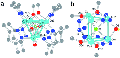
Complex 1 contains six CuII centres distributed in two eclipsed, almost parallel isosceles triangles (Cu1Cu1′Cu2 and Cu3Cu3′Cu4, see Fig. 1), forming an uncommon trigonal prismatic geometry. This trigonal prism has a central F− ligand shared by the six CuII centres, resulting in a sandglass-shaped complex with a μ6-F− bridge (Fig. 1). The Cu–Cu distances inside the triangles (2.833(1)–3.112(1) Å) are slightly shorter than those between the triangles (3.056(2)–3.382(2) Å). Each copper atom presents a distorted square pyramidal geometry with Addison parameters of 0.14, 0.04, 0.13 and 0.12 for Cu1–Cu4, respectively.29 In each case, the basal plane is formed by two nitrogen atoms from two 3,5-Me2pz− ligands and by two oxygen atoms from a μ3-OCH3− and a μ2-OCH3− ligand. The axial ligand is in all cases the fluorine atom (F1) of the central μ6-F− bridge, located between the two copper triangles (Fig. 1).Both isosceles triangles are similar and present a symmetry plane that passes through Cu2 and Cu4 and intersects the Cu1–Cu1′ and Cu3–Cu3′ edges. Besides the common μ6-F− bridge, both triangles are also connected by: (i) a μ2-OH− bridge (O2) connecting Cu2 with Cu4, with a Cu2–O2–Cu4 bond angle of 103.0(3)°; and (ii) two 3,5-Me2pz− ligands connecting Cu1 with Cu3 and Cu1′ with Cu3′ through a Cu–N–N–Cu bridge. Each triangle has a μ3-OCH3− bridge connecting the three Cu atoms. The corresponding μ3-O atoms (O31 and O32) are located 0.97 Å and 0.99 Å out of the Cu2Cu1Cu1′ and Cu4Cu3Cu3′ planes, respectively. Besides these μ3-OCH3− bridges, connectivity inside each triangle is also provided by (i) a μ2-CH3O− bridge connecting the two equivalent copper atoms (Cu1 with Cu1′ and Cu3 with Cu3′); and (ii) two μ2-3,5-Me2pz− bridges connecting the non-equivalent copper atoms (Cu2 with Cu1 and Cu1′ in one triangle and Cu4 with Cu3 and Cu3′ in the other). As observed in the μ3-OCH3− bridges, the oxygen atoms of the μ2-OCH3− bridges (O33 and O34) are not co-planar with the corresponding triangles: O33 is located 0.158 Å above the Cu2Cu1Cu1′ plane and O34 is located 0.276 Å below the Cu4Cu3Cu3′ plane, leading to dihedral angles of 7.0° (Cu2Cu1Cu1′O33) and 11.6° (Cu4Cu3Cu3′O34). In summary, complex 1 has six CuII ions in an uncommon trigonal prismatic geometry connected by a central μ6-F− bridge. The connectivity of the cluster is completed by a μ2-OH− bridge (O2), two μ2-OCH3− bridges (O33 and O34), two μ3-OCH3− bridges (O31 and O32) and six μ2-3,5-Me2pz− bridges, leading to a total anionic charge of −12 that compensates the charge of the six CuII ions.
Although the presence of a central μ6-F− bridge is not straightforward to observe from the X-ray crystal analysis (it could also be a OH− or even a O2− bridge), we have confirmed the presence of fluorine in compound 1 through electron probe microanalysis (EPMA), which indicates the presence of one F atom per Cu6 cluster. Note that, although in the synthetic procedure there is no addition of F−, the partial dissociation of the BF4− counter-anion of the precursor Cu(BF4)2 salt can release F− anions, as has been previously reported.30–37 Once the nature of the central atom is established, the O2 bridge has to be assigned to a OH− group in order to maintain the balance of charge (if this was also a F− atom, it would imply a Cu![[thin space (1/6-em)]](https://www.rsc.org/images/entities/char_2009.gif) :
:![[thin space (1/6-em)]](https://www.rsc.org/images/entities/char_2009.gif) F ratio of 3 instead of 6).
F ratio of 3 instead of 6).
The presence of a μ6-F− bridge is not unprecedented and has been reported in a family of three compounds, in which the F− ion is surrounded by six Ag+ ions in a octahedral environment.38,39 Compound 1 is, however, the first example of a μ6-F− bridge with a trigonal prismatic geometry. Notice also that the presence of any μ6-X bridge surrounded by six CuII ions is very unusual in coordination chemistry. Thus, only four μ6-Cl−,40–42 three μ6-V,43–45 two μ6-S,46,47 one μ6-Br,48 one μ6-I,49 one μ6-O2−,50 and one μ6-H51 have been reported to date. Among these 13 examples, there is only one (the μ6-Cl− complex [Cu6(μ6Cl)(μ3OCH3)2(μ2pyrazolate)9],42) in which the six copper atoms present a trigonal prismatic geometry as in 1. In summary, 1 is the first copper complex with a μ6-F− bridge, and the first example for any metal with trigonal prismatic geometry around a μ6-F atom.
Besides the central μ6-F− bridge, the trigonal prismatic arrangement of the six CuII ions is stabilized by two μ2-3,5-Me2pz− bridges connecting Cu1–Cu3 and Cu1′-Cu3′, a μ2-OH− bridge connecting Cu2 and Cu4 and by two quite strong π–π interactions between the rings of the μ2-Me2pz− bridges, forming two of the three edges of the triangles (the distance between the average planes of the 3,5-Me2pz− ligands is 3.73 Å, Fig. 1a).52 Note that an octahedral arrangement of the six CuII ions would weaken all these interactions except the central μ6-F− one.
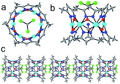
Complex 2 also contains a Cu6 cluster, although with a regular planar hexagonal arrangement of the six equivalent CuII ions (Fig. 2a). This hexagonal wheel-like structure is packed in the solid state forming hexagonal channels along the c axis (Fig. 3) with an internal diameter of 6.355 Å (measured as the Cu–Cu distance along the diagonal), and a free pore diameter of ca. 3.5 Å. The CuII ions present a square planar geometry with two trans N atoms (N1 and N2) from two μ2-3,5-Me2pz− ligands, and two trans oxygen atoms (O1) from two μ2-OH− bridges (Fig. 2b). Note that the channel structure of compound 2 suggests the possible inclusion of guest molecules, as will be discussed below.
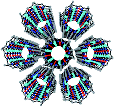 | ||
| Fig. 3 Perspective view along the c direction of the hexagonal channels in the structure of 2. H and solvent atoms are omitted for clarity. Colour code: Cu = cyan, O = red, N = dark blue, C = grey. | ||
Each pair of two consecutive CuII ions are connected by two different bridges, alternating on one or the other side of the ring: (i) a –N–N– bridge from a μ2-3,5-Me2pz− bridge and (ii) a μ2-OH− bridge with a Cu1–O1–Cu1 bond angle of 110.18° (Fig. 2b). The Cu–O and the Cu–N bond lengths are all similar (in the range 1.936–1.960 Å). The Cu–Cu distance along the side of the hexagon is 3.178(2) Å.
The hexagonal ring in 2 resembles the numerous examples of metalla-crown complexes, whose very interesting host–guest interactions and potentialities have been reviewed by Pecoraro et al.,53 although in 2 the connecting unit between two oxygen atoms is a CuII centre instead of a –M–N– bridging group. In addition, an interesting feature of this structure is the presence of a CHCl3 and a CH3CN molecule inside the Cu6 ring (confirmed by thermo-gravimetric analysis, Fig. S3†). Both molecules present a positional disorder over two related positions with occupancy factors of 1/2. The CHCl3 molecules are always located above (or below) the Cu6 plane with the three Cl atoms pointing out of the ring and the H atom pointing towards the centre of the ring (Fig. 2c). The CH3CN molecules are in the centre of the molecule with the N atom located in the Cu6 plane and the two C atoms pointing to one or the other side, depending on the position of the CHCl3 molecule (Fig. 2). Since single crystals of compound 2 are only obtained from a CHCl3 solution after slow diffusion of CH3CN, it seems that both solvent molecules play an important templating role in the crystallization of the Cu6 metalla-cycle.
This kind of Cu6 ring structure with double bridges (O and –N–N–) has already been described in a few cases,54–59 although they are all charged or contain an ion (mainly Cl−, Br−, I− or NO2−). Interestingly, in 2 the Cu6 ring structure is charge-balanced and, therefore, 2 is the first example of a neutral Cu6 ring of this type without any counter-ion inside. This fact explains the eclipsed packing of the rings leading to an unprecedented tubular structure with hexagonal channels that can be evacuated (Fig. 3).
One-dimensional pores are highly interesting, since their tubular topology can afford a high adsorption capacity with size selectivity and one dimensional diffusion properties. The presence of the solvent molecules in the Cu6 channels prevents the crystal from exhibiting a well-defined nano-porous structure, as occurs in other metalla-cycles. Still, as these solvent molecules are neutral, they can be partially removed upon heating in a single-crystal-to-single-crystal process, without loss of crystallinity. This affords a porous material (15–17% of the unit cell volume) with a pore diameter of ca. 3.55 Å, slightly larger than the kinetic CO2 diameter (3.30 Å). Indeed, preliminary gas sorption studies show that CO2 molecules can partially enter into the one-dimensional pores with an uptake of up to ca. 30% v/v of CO2 in the hexagonal channels of a de-solvated sample of compound 2 with a CO2 pressure of ca. 1 atm (Fig. S4†).
Stability in solution of the Cu6 compounds
A green CHCl3 solution of compound 1 presents an ESI-mass spectrum with four main signals centred at m/z = 1069.23, 1049.13, 1021.25 and 1003.18 Da in the positive region (Fig. 4). These four signals can be attributed to hexanuclear CuII complexes with 3,5-Me2pz− (L) bridges presenting different degrees of hydrolysis and different amounts of O2−, OH− and CH3O− bridges: {Cu6(L)6(F)(OH)3(O)(CH3O) − 2e−}+ (m/z = 1069.06), [Cu6(L)6(F)(O)(CH3O)2]+ (m/z = 1049.08), [Cu6(L)6(F)(O)(OH)2]+ (m/z = 1021.07) and [Cu6(L)6(F)(O)2]+ (m/z = 1003.01), with isotopic patterns matching those observed experimentally (Fig. 4), confirming the presence of the μ6-F− hexanuclear CuII complex 1 in solution and its stability.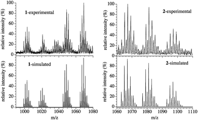 | ||
| Fig. 4 Experimental (top) and simulated (bottom) ESI-mass spectra of compounds 1 (left) and 2 (right). | ||
The ESI-mass spectrum of compound 2 dissolved in a 1![[thin space (1/6-em)]](https://www.rsc.org/images/entities/char_2009.gif) :
:![[thin space (1/6-em)]](https://www.rsc.org/images/entities/char_2009.gif) 1 CHCl3–CH3OH mixture shows three main signals centred at m/z = 1067.17, 1081.18 and 1097.21 Da in the positive region (Fig. 4). These three signals correspond to those expected for an ionized Cu6 wheel with a partial substitution of one, two or three μ-OH− bridges by the corresponding μ-OCH3− bridges, together with the loss (or gain) of H atoms and electrons (Fig. 4). We can conclude that the {[Cu6(3,5-Me2pz)6(OHn)(OH)5−x(CH3O)x] − ze−}+ monocations with x = 1 and 2 (n/z = 0/2), and x = 3 (n/z = 2/0) with average masses of 1067.07, 1081.10 and 1097.14 Da and with isotopic patterns matching those observed experimentally are present in the solution, showing the stability of the Cu6 wheel and the progressive OH−/CH3O− ligand exchange.
1 CHCl3–CH3OH mixture shows three main signals centred at m/z = 1067.17, 1081.18 and 1097.21 Da in the positive region (Fig. 4). These three signals correspond to those expected for an ionized Cu6 wheel with a partial substitution of one, two or three μ-OH− bridges by the corresponding μ-OCH3− bridges, together with the loss (or gain) of H atoms and electrons (Fig. 4). We can conclude that the {[Cu6(3,5-Me2pz)6(OHn)(OH)5−x(CH3O)x] − ze−}+ monocations with x = 1 and 2 (n/z = 0/2), and x = 3 (n/z = 2/0) with average masses of 1067.07, 1081.10 and 1097.14 Da and with isotopic patterns matching those observed experimentally are present in the solution, showing the stability of the Cu6 wheel and the progressive OH−/CH3O− ligand exchange.
Conversion from 1 to 2
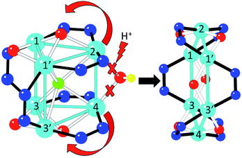
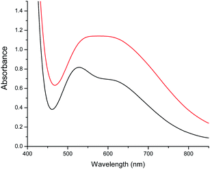
When a CHCl3 solution of 1 is left to stand in open air, a colour change from green to purple is observed on the surface after a few hours. This colour change is caused by the diffusion of water molecules from the air, and can indeed be promoted by addition of water, yielding a purple solution that, upon slow diffusion of acetonitrile, affords single crystals of 2. Thus, conversion of 1 into 2 can be achieved in this way. A possible pathway for this conversion is depicted in Fig. 5. The addition of water molecules may cause the hydrolysis of the easily accessible μ2-OH− (O2) and the two μ3-OCH3− bridges (O32 and O33 in Fig. 1). This kind of process has already been observed in other similar trinuclear pyrazolato-CuII complexes with alkoxido bridges.60 Once hydrolysed, these three bridges are released, allowing the unfolding of the Cu6 trigonal prism into a planar Cu6 hexagon by a simple rotation of 90° of both triangles around the Cu3–Cu3′ and Cu1–Cu1′ edges (Fig. 5). Note that this mechanism does not imply cleavage nor formation of any Cu–N bond during the process, since the number and connectivity of the μ2-3,5-Me2pz− ligands remains the same in both compounds. The transformation of the Cu6 arrangement is clearly followed by the change of colour of the solution (from green to purple). Addition of CH3CN to the purple solution containing the wheels permits the crystallization of 2.In order to check if the conversion of 1 into 2 is reversible, we have followed the changes in colour of a solution containing these species upon changing the solvent mixture. We have found that by adding methanol to the purple solution of 2, the colour changes to a green colour very close to that of the original solution of 1, but not identical, indicating that complex 2 is transformed into a complex very similar to 1 under these conditions. These colour changes have been monitored in a more precise way by recording UV-vis absorption spectra. In the visible region 1 shows a broad double maximum in the range of 550 to 600 nm, while 2 shows a maximum at 528 nm (ε = 512) and a shoulder at ca. 610 nm (Fig. 6).
The spectra of a solution of 2 in 160 μL of CHCl3 with different added aliquots of CH3OH (10 μL to 160 μL) are shown in Fig. 7. These show that the maximum at 528 nm decreases in intensity upon addition of CH3OH, and eventually disappears. At the same time a new maximum starts to appear when 60 μL of CH3OH is added. This new maximum increases in intensity and moves to lower energies to reach a constant value of 630 nm when 160 μL has been added. This maximum is similar, although not identical, to that observed in the spectrum of 1 in a solution of CHCl3 and 160 μL of CH3OH (Fig. S5†), and indicates that compound 2 converts into a compound closely related to 1. Two isosbestic points at approximately 473 and 525 nm are also observed, indicating that an equilibrium between both species is established when small quantities of CH3OH are added to an initial CHCl3 solution (Fig. 7).
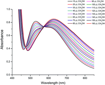 | ||
| Fig. 7 Visible spectra of compound 2 in CHCl3 with different quantities of CH3OH, showing the transformation of 2 into a complex similar to 1. | ||
Finally, it should be mentioned that when 10 μL of H2O was added to a solution of 1 in CHCl3 plus 160 μL of CH3OH, the colour of the solution changed from green to blueish-purple, indicating that 2 is formed. When larger amounts of water were added, the visible spectra of these solutions remained practically identical to that of a solution of 2 in these solvents (Fig. S6†), until the addition of 30 μL of H2O; at that point the organic solution formed a suspension.
All these transformations have also been followed with ESI-mass spectroscopy. The addition of water to a green solution containing 1 leads to the formation of a purple solution whose ESI-mass spectrum is the same as a solution of 2 in CHCl3 (Fig. 4), which clearly demonstrates the transformation of 1 into 2. Finally, the addition of an excess of CH3OH to the purple solution of 2 results in a green solution that contains trimeric CuII units connected by 3,5-Me2pz− (L) ligands with a presumed structure very similar to that present in 1. The ESI-mass spectrum of this resulting green solution presents three main signals centred at m/z = 666.24, 602.42 and 571.23 Da (Fig. S8†), corresponding to CuII trimers with different hydrolysis degrees and different amounts of CH3OH and CH3O− bridges: {[Cu3(L)3(CH3OH)4(CH3O)2]}+ (m/z = 666.24), {[Cu3(L)3(CH3OH)2(CH3O)2]}+ (m/z = 602.16) and {[Cu3(L)3(CH3OH)2(CH3O)]+1e−}+ (m/z = 571.12). These spectra indicate that 1 transforms into 2, whereas 2 transforms into a trimeric CuII cluster very similar to each of the two trimeric species that form compound 1, although containing only CH3O− and CH3OH bridges but no hydroxido or fluoride ones.
A possible explanation of the non-reversibility of the reaction is the lack of F− anions in the medium that could act as μ6-bridges. However, even in the presence of an excess of F− (or BF4−), the Cu6 wheel does not convert back into 1.
Magnetic properties
These two Cu6 complexes exhibit strong differences in their magnetic behaviour, which can be correlated with their molecular structures. Thus, for 1 a smooth decrease of the product of the molar magnetic susceptibility and temperature (χmT) is observed upon cooling, exhibiting a χmT value of ca. 1.9 emu K mol−1 at 300 K, which decreases to reach an intermediate χmT value of 0.7 emu K mol−1 at 10 K, and finally shows a sharp decrease at lower temperatures. In contrast, for 2 this decrease is much sharper, exhibiting a much lower χmT value even at room temperature (0.5 emu K mol−1), which tends to be zero below 50 K (Fig. 8). Qualitatively this difference indicates that in these magnetic clusters the CuII spins are much more strongly antiferromagnetically coupled in 2 than in 1. It also indicates that for 2, the antiferromagnetic spin state S = 0 is the ground state, being well separated in energy from the first excited spin states, while for 1 the spin states S = 0 and S = 1 must be quasi-degenerate to explain the tendency of χmT to reach an intermediate value (ca. 0.7 emu K mol−1) at low temperatures. In other words, in this last cluster the behaviour is dominated by two antiferromagnetic triangles, each having a ground spin state of S = 1/2. In the frame of this model, the sharp decrease in χmT observed in the low temperature limit should indicate the presence of weaker antiferromagnetic coupling between these two triangular units.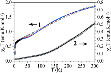 | ||
| Fig. 8 Thermal variation of χmT per Cu6 unit in 1 and 2. Solid lines are the best fit to the models (see text). | ||
In order to give a quantitative explanation, these magnetic data have been fitted to spin models that take into account the structural features of these Cu6 magnetic clusters using the package MAGPACK.61,62 In these models, the Hamiltonian describing the exchange interaction between sites i and j is written as −JSiSj. Structurally, 1 possesses two isosceles triangles connected through three different bridges (two μ2-3,5-Me2pz−, one μ2-OH− and the central μ6-F−, Fig. 1). This low symmetry leads to a complex exchange network formed by two exchange interactions inside the triangles and two different exchange interactions connecting the two triangles (Scheme 2). Taking into account the above remarks, we first extracted the exchange interactions within the triangles (J1 and J2) by fitting the magnetic data in the temperature range 30 K < T < 300 K to an isolated triangle (i.e., J3 and J4 have been fixed to 0). The resulting curve is plotted as a red line in Fig. 8 (extrapolated down to 2 K). In a second step, to fit the low temperature behaviour, we fixed J1 and J2 to these values, while allowing J3 and J4 to vary. As these two parameters have been found to be strongly correlated, we have performed DFT calculations to estimate J3 (ESI†). The obtained value for J3 (−22 cm−1) agrees well with the calculated values for two similar pyrazolato bridges in two closely related Cu6 trigonal prisms.42,63 Note that this J3 exchange pathway involves a pyrazolato Cu–N–N–Cu bridge, and that this bridge gives rise to antiferromagnetic coupling when the pyrazolate bridge connects two basal positions, but the magnitude strongly depends on the angle formed by the two basal planes. Thus, when the two basal planes are coplanar, the antiferromagnetic coupling is strong, but when this angle decreases, the magnetic coupling significantly decreases.64–66 In 1 the two basal planes are far from being coplanar, forming an angle of 58.6° and, therefore it is expected to lead to a weak antiferromagnetic coupling, in agreement with the calculated J3 value (−22 cm−1). Fixing this value in the fitting procedure, the final set of exchange parameters is J1 = −94 cm−1; J2 = −131 cm−1, J3 = −22 cm−1 and J4 = −4 cm−1 (the fit with these values corresponds to the blue line in Fig. 8). As can be seen in Scheme 2, J1 (−94 cm−1) corresponds to a double bridge formed by a pyrazolate (–N–N–) and a methoxido bridge. This kind of bridge is well known to produce moderate to strong antiferromagnetic (AF) couplings (in the range ca. −160 to −550 cm−1),16 with stronger AF coupling as the Cu–O–Cu angle increases. In 1 this angle is very small (102.1(2)°) compared with most of the reported examples (with angles in the range ca. 120–130° and, accordingly, this AF coupling is weaker than those observed in the other examples). The second coupling constant, J2, (−131 cm−1) corresponds to a double methoxido bridge (Scheme 2 and Fig. 1). The coupling through this kind of bridge is mainly determined by the Cu–O–Cu bond angle (α) and the angle formed by the C–O bond with the Cu2O2 central unit (τ) when this central unit is planar.67,68 These correlations establish that when τ = 0, the coupling is AF for α angles above ca. 88.5°, but for τ = 40° the crossing point shifts to ca. 94.5°. In 1 the Cu–O–Cu angles are 90.8(2)° (Cu1–O31–Cu1′) and 96.5(3)° (Cu1–O33–Cu1′) and the corresponding τ angles are ca. 40° and ca. 10°, respectively (the lack of planarity of the central Cu2O2 unit precludes a precise calculation of τ). These values suggest that the Cu1–O31–Cu1′ exchange pathway should be weak and ferromagnetic, whereas the Cu1–O33–Cu1′ pathway should be stronger and AF, resulting in the observed moderate AF coupling for this double methoxido bridge. Note also that the lack of planarity in the basal planes of Cu1 and Cu1′ or Cu3 and Cu3′ (the dihedral angles between their average planes are 135.5° and 133.6°, respectively) is expected to further decrease the resulting magnetic exchange. Finally, J4 (−4 cm−1) corresponds to a hydroxido bridge with a Cu–O–Cu bond angle of 103.0(3)°. Note that previous magneto-structural correlations in this kind of bridge67,68 indicate that, in general, this coupling should be strongly antiferromagnetic. The much weaker coupling observed for this bridge in 1 has to be attributed to the fact that the basal planes of the two CuII ions are almost orthogonal (the dihedral angle is 94.9°), resulting in an almost null orbital overlap.
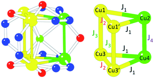 | ||
| Scheme 2 Magnetic exchange scheme and coupling constants used to fit the magnetic properties of the Cu6 cluster in 1. | ||
Compound 2 at room temperature shows a χmT value of ca. 0.5 emu K mol−1 per Cu6 ring, well below that expected for six independent CuII ions. When the temperature is decreased, χmT shows a continuous decrease to reach a value of ca. 0.02 emu K mol−1 at 2 K (Fig. 8). This behaviour indicates that compound 2 shows a strong antiferromagnetic coupling inside the Cu6 cluster with a small contribution from paramagnetic impurities. The isothermal magnetization at 2 K (Fig. S9†) confirms this behaviour. In compound 2 the model used to fit the magnetic properties is much more simple, since the six coupling constants inside the Cu6 ring are identical, and therefore we only need to consider one exchange constant. The fitting was done by the same methodology used for 1.61,62 With this simple model the magnetic properties of compound 2 can be very well reproduced over the whole temperature range, including a paramagnetic monomeric CuII impurity (ρ) with the following parameters: J1 = −454 cm−1 and ρ = 0.23%, with a fixed value of g = 2.1 (solid line in Fig. 8).
The value found for the coupling constant in compound 2 is close to those found in other similar Cu complexes with the same kind of double bridge and similar structural parameters.16
Furthermore, from previous magneto-structural correlations in CuII complexes with hydroxido bridges,67,68 in compound 2 we can estimate a J value of ca. −450 cm−1, in very good agreement with the experimental value.
Conclusions
In this work we present the structural and magnetic characterization of two new hexanuclear CuII complexes: [Cu6(μ6F)(μ2OH)(μ3OCH3)2(μ2OCH3)2(3,5-Me2pz)6] (1) and [Cu6(μ2OH)6(3,5-Me2pz)6]·CH3CN·CHCl3 (2), and a possible mechanism of the transformation of 1 into 2. Complex 1 exhibits a sandglass-like structure, and represents the first copper complex with a μ6-F− bridge and the first metallic complex with trigonal prismatic geometry around a μ6-F atom. Compound 2 is formed from a neutral and soluble wheel-like Cu6 complex, which packs in the solid state to give a tubular structure that contains CH3CN and CHCl3 molecules in the hexagonal channels formed by the eclipsed packing of the Cu6 rings. These solvent molecules can be removed and partially exchanged with CO2 since the removal of the solvent molecules does not alter the crystal structure of 2. Visible and mass spectra confirm the conversion of 1 into 2 by simply changing the solvent conditions. The stability of the Cu6 wheel in solution opens up the possibility of preparing thin films of this entity with a mono-disperse porous tubular structure by using different solution-based techniques. These two compounds exhibit very different magnetic behaviours, in agreement with their structural features. Thus, the spin structure of 1 shows a ground state formed of quasi-degenerate S = 0 and S = 1 spin levels, as it is dominated by a spin frustration effect within the two antiferromagnetic triangles. In turn, 2 shows an antiferromagnetic ground spin state S = 0, which is well separated in energy from the first excited S = 1 spin state (by more than 62 cm−1), as a consequence of the very strong antiferromagnetic Cu–Cu interactions and of the hexagonal topology of the exchange network.Acknowledgements
We acknowledge the European Union (Advanced ERC grant SPINMOL), the Spanish MINECO (projects Consolider-Ingenio in Molecular Nanoscience, CTQ2011-26507 and MAT2011-22785) and the Generalidad Valenciana (Prometeo and ISIC-Nano Programs) for financial support. The work in Chile has been supported by the Financiamiento Basal Program FB0807. WCM thanks CONICYT for Doctoral Scholarships (21080445 and AT24100006), and Becas Chile. The authors also thank Powered@NLHPC. This research was partially supported by the Supercomputing Infrastructure of the National Laboratory for High Performance Computing, NLHPC (ECM-02), Centre for Mathematical Modeling (CMM), Universidad de Chile. Thanks are given to the Spanish CSIC for the award of a license for the use of the Cambridge Crystallographic Data Base (CSD). We thank Dr J. M. Clemente for helpful discussions in the fitting of the magnetic data.References
- M. Fu, I. Issac, D. Fenske and O. Fuhr, Angew. Chem., Int. Ed., 2010, 49, 6899–6903 CrossRef CAS PubMed.
- B. Murphy and B. Hathaway, Coord. Chem. Rev., 2003, 243, 237–262 CrossRef CAS.
- A. M. Kirillov, M. V. Kirillova and A. J. L. Pombeiro, Coord. Chem. Rev., 2012, 256, 2741–2759, DOI:10.1016/j.ccr.2012.07.022.
- E. I. Solomon, U. M. Sundaram and T. E. Machonkin, Chem. Rev., 1996, 96, 2563–2606 CrossRef CAS PubMed.
- D. Desbouis, I. P. Troitsky, M. J. Belousoff, L. Spiccia and B. Graham, Coord. Chem. Rev., 2012, 256, 897–937 CrossRef CAS PubMed.
- I. Blain, P. Slama, M. Giorgi, T. Tron and M. Réglier, Rev. Mol. Biotechnol., 2002, 90, 95–112 CrossRef CAS.
- M. C. Feiters, Comments Inorg. Chem., 1990, 11, 131–174 CrossRef CAS.
- V. Wing-Wah Yam, K. Kam-Wing Lo, W. Kit-Mai Fung and C. Wang, Coord. Chem. Rev., 1998, 171, 17–41 CrossRef.
- G. Givaja, P. Amo-Ochoa, C. J. Gómez-García and F. Zamora, Chem. Soc. Rev., 2012, 41, 115–147 RSC.
- O. Kahn, Molecular Magnetism, VCH Publishers, USA, 1993 Search PubMed.
- E. Coronado, M. Giménez-Marqués, G. Mínguez Espallargas and L. Brammer, Nat. Commun., 2012, 3, 828 CrossRef PubMed.
- E. Coronado and G. Minguez Espallargas, Chem. Soc. Rev., 2013, 42, 1525–1539 RSC.
- G. M. Sheldrick, Acta Crystallogr., Sect. A: Found. Crystallogr., 2008, 64, 112–122 CrossRef CAS PubMed.
- A. Spek, J. Appl. Crystallogr., 2003, 36, 7–13 CrossRef CAS.
- G. A. Bain and J. F. Berry, J. Chem. Educ., 2008, 85, 532–536 CrossRef CAS.
- Y. Elerman, H. Kara and A. Elmali, Z. Naturforsch., A: Phys. Sci., 2003, 58, 363–372 CAS.
- G. A. Ardizzoia, M. A. Angaroni, G. La Monica, N. Masciocchi and M. Moret, J. Chem. Soc., Dalton Trans., 1990, 2277–2281 RSC.
- T. O. Denisova, E. V. Amel'chenkova, I. V. Pruss, Z. V. Dobrokhotova, O. P. Fialkovskii and S. E. Nefedov, Russ. J. Inorg. Chem., 2006, 51, 1020–1064 CrossRef.
- G. Mezei and R. G. Raptis, Inorg. Chim. Acta, 2004, 357, 3279–3288 CrossRef CAS PubMed.
- Y. Elerman and A. Elmali, Z. Naturforsch., B: J. Chem. Sci., 2001, 56, 970–974 CAS.
- Y. Elerman, H. Kara and A. Elmali, Z. Naturforsch., B: J. Chem. Sci., 2001, 56, 1129–1137 CAS.
- H. Kara, Y. Elerman and K. Prout, Z. Naturforsch., B: J. Chem. Sci., 2001, 56, 719–727 CAS.
- H. Kara, Y. Elerman and K. Prout, Z. Naturforsch., B: J. Chem. Sci., 2000, 55, 796–802 CAS.
- V. Chandrasekhar, L. Nagarajan, R. Clerac, S. Ghosh, T. Senapati and S. Verma, Inorg. Chem., 2008, 47, 5347–5354 CrossRef CAS PubMed.
- V. Chandrasekhar and S. Kingsley, Angew. Chem., Int. Ed., 2000, 39, 2320–2322 CrossRef CAS.
- J. He, Y. Yin, T. Wu, D. Li and X. Huang, Chem. Commun., 2006, 2845–2847 RSC.
- M. K. Ehlert, S. J. Rettig, A. Storr, R. C. Thompson and J. Trotter, Can. J. Chem., 1990, 68, 1444–1449 CrossRef CAS PubMed.
- G. A. Ardizzoia, M. A. Angaroni, G. La Monica, F. Cariati, S. Cenini, M. Moret and N. Masciocchi, Inorg. Chem., 1991, 30, 4347–4353 CrossRef CAS.
- A. W. Addison, T. N. Rao, J. Reedijk, J. van Rijn and G. C. Verschoor, J. Chem. Soc., Dalton Trans., 1984, 1349–1356 RSC.
- J. A. Carroll, R. E. Cobbledick, F. W. B. Einstein, N. Farrell, D. Sutton and P. L. Vogel, Inorg. Chem., 1977, 16, 2462–2469 CrossRef CAS.
- M. Hidai, T. Kodama, M. Sato, M. Harakawa and Y. Uchida, Inorg. Chem., 1976, 15, 2694–2697 CrossRef CAS.
- P. B. Hitchcock, M. F. Lappert and R. G. Taylor, J. Chem. Soc., Chem. Commun., 1984, 1082–1084 RSC.
- F. J. Rietmeijer, R. A. G. De Graaff and J. Reedijk, Inorg. Chem., 1984, 23, 151–156 CrossRef CAS.
- R. H. Crabtree, G. G. Hlatky and E. M. Holt, J. Am. Chem. Soc., 1983, 105, 7302–7306 CrossRef CAS.
- S. Herold and S. J. Lippard, Inorg. Chem., 1997, 36, 50–58 CrossRef CAS.
- Y. Zang, H. G. Jang, Y. Chiou, M. P. Hendrich and L. Que, Jr, Inorg. Chim. Acta, 1993, 213, 41–48 CrossRef CAS.
- V. Terruzzi, U. Comin, F. De Grazia, G. L. Toti, A. Zambelli, S. Beretta and G. Minoli, Gastrointest. Endosc., 2000, 51, 23–27 CrossRef CAS.
- Q. Wang, G. Guo and T. C. W. Mak, Polyhedron, 2003, 22, 217–223 CrossRef CAS.
- Q. Wang and T. C. W. Mak, Chem. Commun., 2000, 1435–1436 RSC.
- E. V. Lider, E. V. Peresypkina, A. I. Smolentsev, V. N. Elokhina, T. I. Yaroshenko, A. V. Virovets, V. N. Ikorskii and L. G. Lavrenova, Polyhedron, 2007, 26, 1612–1618 CrossRef CAS PubMed.
- E. V. Govor, A. B. Lysenko, D. Quinonero, E. B. Rusanov, A. N. Chernega, J. Moellmer, R. Staudt, H. Krautscheid, A. Frontera and K. V. Domasevitch, Chem. Commun., 2011, 47, 1764–1766 RSC.
- A. Kamiyama, T. Kajiwara and T. Ito, Chem. Lett., 2002, 980–981 CrossRef CAS.
- D. G. Chen, H. H. Zhang and X. F. Yu, Chin. J. Struct. Chem., 2003, 22, 591–594 CAS.
- C. D. Scattergood, P. G. Bonney, J. M. Slater, C. D. Garner and W. Clegg, J. Chem. Soc., Chem. Commun., 1987, 1749–1750 RSC.
- F. Zheng, H. H. Zhang, R. P. Zhou, Y. S. Wu, X. F. Yu and J. S. Huang, Chin. J. Struct. Chem., 1997, 16, 392 CAS.
- R. E. Marsh, Acta Crystallogr., Sect. B: Struct. Sci., 1997, 53, 317–322 Search PubMed.
- P. Lin, X. Wu, L. Chen, L. Wu and W. Du, Polyhedron, 2000, 19, 2189–2193 CrossRef CAS.
- Z. Wei, H. Li, M. Cheng, X. Tang, Y. Chen, Y. Zhang and J. Lang, Inorg. Chem., 2009, 48, 2808–2817 CrossRef CAS PubMed.
- E. Jalilian and S. Lidin, CrystEngComm, 2011, 13, 5730–5736 RSC.
- B. Li, J. Zhao, S. Zheng and G. Yang, Inorg. Chem., 2009, 48, 8294–8303 CrossRef CAS PubMed.
- R. D. Kohn, Z. Pan, M. F. Mahon and G. Kociok-Kohn, Chem. Commun., 2003, 1272–1273 RSC.
- C. A. Hunter and J. K. M. Sanders, J. Am. Chem. Soc., 1990, 112, 5525–5534 CrossRef CAS.
- G. Mezei, C. M. Zaleski and V. L. Pecoraro, Chem. Rev., 2007, 107, 4933–5003 CrossRef CAS PubMed.
- J. J. Henkelis, L. F. Jones, M. P. de Miranda, C. A. Kilner and M. A. Halcrow, Inorg. Chem., 2010, 49, 11127–11132 CrossRef CAS PubMed.
- A. A. Mohamed, A. Burini, R. Galassi, D. Paglialunga, J. Galán-Mascarós, K. R. Dunbar and J. P. Fackler, Inorg. Chem., 2007, 46, 2348–2349 CrossRef CAS PubMed.
- E. V. Govor, A. B. Lysenko, D. Quinonero, E. B. Rusanov, A. N. Chernega, J. Moellmer, R. Staudt, H. Krautscheid, A. Frontera and K. V. Domasevitch, Chem. Commun., 2011, 47, 1764–1766 RSC.
- A. A. Mohamed, S. Ricci, A. Burini, R. Galassi, C. Santini, G. M. Chiarella, D. Y. Melgarejo and J. P. Fackler, Inorg. Chem., 2011, 50, 1014–1020 CrossRef CAS PubMed.
- G. Mezei, P. Baran and R. G. Raptis, Angew. Chem., Int. Ed., 2004, 43, 574–577 CrossRef CAS PubMed.
- J. Liu, J. Zhuang, X. You and X. Huang, Chem. Lett., 1999, 28, 651–652 CrossRef.
- G. Mezei, R. G. Raptis and J. Telser, Inorg. Chem., 2006, 45, 8841–8843 CrossRef CAS PubMed.
- J. J. Borrás-Almenar, J. M. Clemente-Juan, E. Coronado and B. S. Tsukerblat, Inorg. Chem., 1999, 38, 6081–6088 CrossRef PubMed.
- J. J. Borrás-Almenar, J. M. Clemente-Juan, E. Coronado and B. S. Tsukerblat, J. Comput. Chem., 2001, 22, 985–991 CrossRef.
- E. M. Zueva, M. M. Petrova, R. Herchel, Z. Travnicek, R. G. Raptis, L. Mathivathanan and J. E. McGrady, Dalton Trans., 2009, 5924–5932 RSC.
- S. O. Malinkin, Y. S. Moroz, L. V. Penkova, V. V. Bon, E. Gumienna-Kontecka, V. A. Pavlenko, V. I. Pekhnyo, F. Meyer and I. O. Fritsky, Polyhedron, 2012, 37, 77–84 CrossRef CAS PubMed.
- M. F. Iskander, T. E. Khalil, W. Haase, R. Werner, I. Svoboda and H. Fuess, Polyhedron, 2001, 20, 2787–2798 CrossRef CAS.
- V. Mishra, F. Lloret and R. Mukherjee, Eur. J. Inorg. Chem., 2007, 2161–2170 CrossRef CAS.
- E. Ruiz, P. Alemany, S. Alvarez and J. Cano, Inorg. Chem., 1997, 36, 3683–3688 CrossRef CAS PubMed.
- E. Ruiz, P. Alemany, S. Alvarez and J. Cano, J. Am. Chem. Soc., 1997, 119, 1297–1303 CrossRef CAS.
Footnote |
| † Electronic supplementary information (ESI) available: CCDC 927862–927865. For ESI and crystallographic data in CIF or other electronic format see DOI: 10.1039/c3sc52628c |
| This journal is © The Royal Society of Chemistry 2014 |

