Magnetically separable core–shell iron oxide@nickel nanoparticles as high-performance recyclable catalysts for chemoselective reduction of nitroaromatics†
Puran Singh
Rathore
a,
Rajesh
Patidar
b,
T.
Shripathi
c and
Sonal
Thakore
*a
aDepartment of Chemistry, Faculty of Science, The M. S. University of Baroda, Vadodara, 390002, India. E-mail: chemistry2797@yahoo.com; Fax: +91 0265 2429814; Tel: +91 0265 2795552
bAnalytical Discipline and CIF, Central Salt and Marine Chemicals Research Institute (CSIR-CSMCRI), G. B. Marg, Bhavnagar, 364002, Gujarat, India
cUGC-DAE Consortium for Scientific Research, Indore 452 001, India
First published on 8th August 2014
Abstract
A magnetically separable core–shell iron oxide@nickel (IO@Ni) nanocatalyst was synthesized by reduction of Ni2+ ions in the presence of iron oxide (Fe2+, Fe3+) by a simple one-pot synthetic route using NaBH4 as a reducing agent and starch as a capping agent. The synthesized nanoparticles (NPs) were characterized by several techniques such as X-ray diffraction (XRD), high resolution transmission electron microscopy (HR-TEM), selected area electron diffraction (SAED), and energy dispersive X-ray spectroscopy (EDS). The core–shell iron oxide@nickel nanoparticles (IO@NiNPs) were found to have excellent activity for the hydrogenation reactions of aromatic nitro compounds under mild conditions using water as a green solvent. Excellent chemoselectivity and recyclability up to 30 cycles for the nitro group reduction was demonstrated.
Introduction
The concept of “Green Chemistry” has become one of the guiding principles of environmentally benign synthesis.1–3 Nanomaterial-catalyzed transformations in an aqueous reaction medium are one of the ideal solutions for the development of green and sustainable protocols. Nanocatalysis is a rapidly growing field which involves the use of metal nanoparticles as catalysts for a variety of organic reactions.4 The preparation and use of magnetic nanoparticles (MNPs) offers advantages in clean and sustainable chemistry as they are non-toxic, readily accessible, and retrievable.5 Additionally, the activity and selectivity of magnetic nano-catalysts can be manipulated by their surface modification.The development and design of core–shell nanomaterials has emerged in recent years because of their multifaceted applications especially as catalysts for organic reactions.6,7 Magnetically separable nanocatalysts are an important class of core–shell nanocatalyst, which are robust, air stable, avoid traditional filtration processes and are recyclable.8 Various methods have been developed to synthesize specific application-based MNPs.9–13 Some of them are aimed at developing materials from waste such as iron tailings. Tailings refer to the waste material of beneficiation processes. Among several iron-based solid waste materials, iron ore tailings (IOTs) are one of the fast accumulating wastes throughout the world due to the rapid expansion of iron and steel based industries and is becoming one of the serious environmental threats for the future generation. Presently, IOTs are mainly used with very little intervention of high technology and moreover, value addition is low. As a result, there is an increasing interest in the search for possible alternative uses of waste IOTs such as adsorption and catalysis or as precursors to value added products before their final discharge.14–19 Here we assess the potential of synthesizing magnetic iron oxide from IOTs and its use as a template for the synthesis of magnetically separable nickel nanoparticles (NiNPs).
The reduction of nitroarenes is an important process as the products, aromatic amines, are versatile intermediates and precursors in the preparation of dyes, pharmaceuticals, pigments, agrochemicals and polymers.20 The process is complicated as the reduction of a nitro group proceeds in stages and it often stops at an intermediate stage producing hydroxylamine and hydrazine as side products.21 A variety of procedures and reducing agents are available for this purpose.22 In the literature, a few procedures involving noble metal NPs such as Pd, Pt, Ag, Au, as well as Fe, Fe3O4@Ni and Ni@Ag NPs have been demonstrated for the reduction of nitro groups.7,22–24 The main limitations of earlier reported work were the necessity of high H2 pressures, prolonged reaction times, lower turnover numbers, organic solvents, reduced recyclability and high temperatures. Further, the selection of metal and its support, the hydrogen source and operational simplicity, which are the important parameters for effective conversions, are restricted. However, an alternative procedure which is efficient, simple, chemoselective, green and cost-effective would be highly beneficial.
In the past, we have investigated the use of NiNPs as catalysts for transesterification as well as reduction.25 In this paper, we report the first protocol for the synthesis of a starch capped iron oxide@Ni (IO@Ni) core–shell magnetically separable nanocatalyst for the hydrogenation of aromatic nitro compounds. Initially p-nitroaniline (PNA) was used as the model system to simplify the analysis and to accelerate the screening speed. All reactions were carried out at room temperature (rt) in aqueous medium (green solvent). Consequently, the optimized conditions were used for the synthesis of various aromatic amines.
Results and discussions
Synthesis and characterizations of iron oxide (IO)
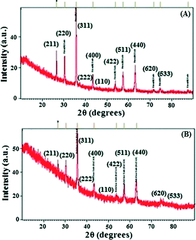
The IOTs selected for the present study primarily consist of Fe, Si and Al with magnetite, hematite and goethite as the main iron bearing phases (ESI†). Si and Al are present in the form of kaolinite which is evident from X-ray diffraction (XRD) patterns (ESI†). Fig. 1A shows the XRD patterns of the as synthesized IO. The lines in Fig. 1A correspond to crystalline phases. It is deduced from this pattern that the sample is composed of mixed phases. Detailed analysis has been carried out based on the Crystallography Open Database (COD). All of the crystallite lines identified with their respective phase(s) are shown in Fig. 1. Details of composition along with its peak positions are shown in ESI.† It is also observed that the pattern is dominated by maghemite (γ-Fe2O3) and magnetite (Fe3O4) phases. It is to be noted here that the peak positions of both the phases are very close to each other, hence exact identification is very difficult. However, based on the intensity distribution, it can be concluded that the majority of the sample consists of maghemite or magnetite phases along with hematite as a secondary phase and goethite as an impurity phase. The XRD pattern is similar to reported data.26,27 SEM-EDX of IO also showed the presence of Fe metal (ESI†).Synthesis and characterizations of IO@NiNPs
A template synthesis method was used for synthesis of magnetic separable core–shell nanoparticles. This method is mainly used to generate specific nanostructures of bimetallic nanoalloys which are otherwise very difficult to prepare. This approach utilizes pre-formed iron oxide as a base metal and subsequently directs the deposition of the Ni metal onto its surface site. In the present study, nanosized nickel was deposited on iron oxide under sonication and starch was used as a capping agent. This method is commonly used to prepare core–shell or multi-shell morphologies. Starch capping was proven by FT-IR (ESI†).Fig. 1B shows the XRD pattern of IO@NiNPs. The signals of Ni were not detected in the XRD pattern of IO@NiNPs although the position and relative intensity of the diffraction peaks are reasonably close to the reported pattern.24b,28 The XRD pattern shows that the MNPs are well-crystalline and exhibit diffraction peaks corresponding to (111), (220), (311), (400), (511) and (440) planes of a cubic crystal system. The XRD pattern indicates mixed phases of iron oxides with nickel.
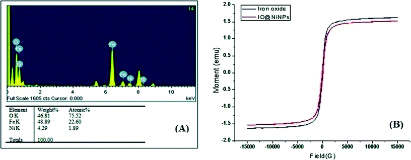
The weight percentage of Ni was determined to be 1.98% by AAS analysis and Energy Dispersive X-ray analysis (EDX) also confirmed the ratio 1.89![[thin space (1/6-em)]](https://www.rsc.org/images/entities/char_2009.gif) :
:![[thin space (1/6-em)]](https://www.rsc.org/images/entities/char_2009.gif) 98.11 (Ni
98.11 (Ni![[thin space (1/6-em)]](https://www.rsc.org/images/entities/char_2009.gif) :
:![[thin space (1/6-em)]](https://www.rsc.org/images/entities/char_2009.gif) iron oxide) (Fig. 2A). EDX analysis indicates that the clean final product is mostly composed of O, Fe and Ni, with no other signals (Fig. 2A).
iron oxide) (Fig. 2A). EDX analysis indicates that the clean final product is mostly composed of O, Fe and Ni, with no other signals (Fig. 2A).
The magnetic measurements on the as-prepared iron oxide and IO@NiNPs have been carried out at room temperature, and the data are shown in Fig. 2B. From the recorded M–H loop, it is clear that both the as-prepared samples are ferromagnetic at RT. The magnetization of the as-prepared iron oxide was 1.6269 emu, and it decreased to a value of 1.5259 emu after coating of NiNPs. The coercivity values of the IO and IO@NiNPs were 73.65 and 61.76 G, respectively. The low magnetization value exhibited by the IO@NiNPs compared to the iron oxide could be due to the presence of impurities/defects in the IO@NiNPs. Since the size of the nanoparticles synthesized by us lies in the range of 20–50 nm, they are still ferromagnetic.
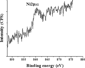
In order to give further evidence of the formation of a NiNP shell over the iron oxide core and to determine the oxidation state of Ni, XPS resolution Ni 2p spectroscopy results of iron oxide and IO@NiNPs were compared (ESI†). The signals of Ni were very faint in the XPS spectrum of IO@NiNPs (Fig. 3) because of low loading of nickel metal. Nevertheless, for a better understanding of the oxidation state of Ni metal, the binding energy obtained from the catalyst was compared with the Ni metal 2p3/2 peak position. The peak value obtained at 852.9 eV is within the range of the literature value (852.7 eV ± 0.4 eV).29 In agreement with the above analyses, it can be concluded that the oxidation state of nickel in the catalyst is zero.
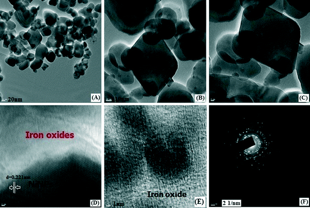
The Brunauer–Emmet–Teller (BET) surface area of a magnetic IO@NiNPs sample was determined to be 17.6546 m2 g−1, demonstrating that these MNPs have a high surface area (ESI†). The pore size of the MNPs was determined to be 25.4629 nm by the Barrett–Joyner–Halenda (BJH) analysis of the isotherms (ESI†). The total pore volumes were 0.051547 cm3 g−1 (ESI†). The High-Resolution Transmission Electron Microscopy (HR-TEM) images of IO@NiNPs show a somewhat spherical morphology with some cubic particles and an average size range of 20–50 nm (Fig. 4A). Fig. 4B and C are HR-TEM images of typical IO@NiNPs at different magnifications. The high resolution images in Fig. 4D and E shows well developed lattice fringes and the fringes extend throughout the particle confirming the monocrystalline nature of the individual particles. The distance between adjacent lattice fringes measured as 0.221 nm in Fig. 4D corresponds to the 311 reflection. The selected area electron diffraction (SAED) pattern shown in Fig. 4F corresponds to the higher order reflections of IO@NiNPs.30 The HR-TEM images (Fig. 4) clearly show that nickel is deposited on the iron oxide surface. In accordance with the above analyses, it can be concluded that the nanoparticles prepared by this method are a mixture of iron oxide and nickel metal nanoparticles.
Catalytic reduction of p-nitroaniline and other aromatic nitro compounds
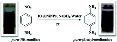
The IO@Ni core–shell nanoparticles were used as a catalyst for the hydrogenation of aromatic nitro compounds using NaBH4 as the hydrogen donor and water as a solvent as shown in Scheme 1. The initial screening of the reduction of p-nitroaniline (PNA) to yield p-phenylenediamine (PPDA) was investigated under various reaction conditions (Table 1). The conversion was monitored by UV-vis spectroscopy, where the product and reactant show different absorption bands at 307 nm and 381 nm, respectively as shown in Fig. 5.| Sr. no. | Catalyst (mg) (IO@NiNPs) | NaBH4 (mmol) | Temperature (°C) | Time | % Yieldc (±2%) |
|---|---|---|---|---|---|
| a Reaction conditions: p-nitroaniline-0.362 mmol, solvent 2 mL (water). b Optimized reaction conditions. c Isolated yield. d Iron oxide only (20 mg). | |||||
| 1 | None | None | 25–30 to reflux | 24 h | — |
| 2 | 12 | None | 25–30 to reflux | 24 h | <5 |
| 3 | None | 1.85 | 25–30 to reflux | 24 h | <10 |
| 4 | IOd | 1.85 | RT | 24 h | 55 |
| 5 | 12 | 1.85 | RT | 12 min | 96 |
| 6b | 12 | 1.44 | RT | 12 min | 96 |
| 7 | 12 | 1.03 | RT | 20 min | 96 |
| 8 | 12 | 0.61 | RT | 30 min | 96 |
| 9 | 12 | 0.20 | RT | 24 h | 90 |
| 10 | 12 | 0.02 | RT | 24 h | 40 |
| 11 | 18 | 1.44 | RT | 12 min | 96 |
| 12 | 15 | 1.44 | RT | 12 min | 96 |
| 13 | 9 | 1.44 | RT | 23 min | 96 |
| 14 | 6 | 1.44 | RT | 32 min | 96 |
| 15 | 3 | 1.44 | RT | 39 min | 96 |
| 16 | 0.3 | 1.44 | RT | 180 min | 96 |
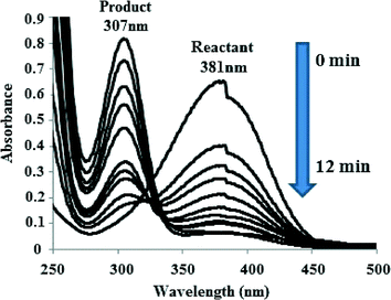 | ||
| Fig. 5 UV-vis spectra indicating the conversion of p-nitroaniline to p-phenylenediamine in the presence of IO@NiNPs. | ||
It is seen from the Table 1 (entries 1–3) that the presence of a catalyst along with NaBH4 is required for hydrogenation of PNA. In our previous study we have observed that nickel nanoparticle-catalysed hydrogenation of PNA takes more than one hour.25b When the reaction was carried out using only IO, the reaction yields were very low (~50 to 55%) even after 24 h at rt (Table 1, entry 4). When the reaction conditions mentioned in the Table (entry 6) were used, the reaction proceeded faster, within 12 min, and the λmax shifted from 381 nm to 307 nm. Whereas, in the absence of NPs, the peak at 381 nm corresponding to PNA did not disappear even after 24 h of reflux. The optimum reaction conditions for PNA reactions are given in Table 1 (entry 6), which yields 96 ± 2% of product at rt after 12 min and selectivity was 100%.
Nanocatalysts can catalyze the reduction of nitro compounds by acting as an electronic relay system to overcome the kinetic barrier, in which the electrons donated by BH4− can be transferred to the acceptor nitro groups.31 The p-nitroaniline and BH4− were adsorbed by the electronic hole in the surface of the NiNPs via chemical adsorption. Immediately, p-phenylenediamine was produced on the surface of NPs. In the second step, the PPDA was desorbed from the surface of the NPs. A detailed mechanism has been proposed by Xie et al.32
Furthermore, experiments were performed using a different mole ratio of NaBH4 in the standard reaction. When we decreased the molar quantity of NaBH4 from 1.85 mmol to 1.44 mmol the yield and reaction time did not change (Table 1, entries 5 and 6), whereas using 1.44 mmol of NaBH4 resulted in a remarkable yield (96 ± 2%) at 25–30 °C within 12 min (Table 1, entry 6). However, further lowering the amount of NaBH4 caused an increase in the reaction time (entries 6 to 10) and hence an adequate quantity of NaBH4 was used for the optimum reaction conditions.
Variation in the quantity of NPs (Table 1, entries 11 to 16) under optimum reaction conditions showed that even 0.3 mg was sufficient for catalyzing the reaction at rt. But the reaction time increased to 180 min for maximum conversion (Table 1, entry 16). On the other hand, with 9 mg the reaction time decreased to 23 min (Table 1, entry 9). Beyond 12 mg the reaction time and yield did not change (Table 1, entries 11 and 12).
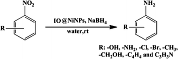
In order to assess the efficiency of the NPs further, the quantity of water and substrate were also optimized (ESI†). After optimization of the reaction conditions (Table 1 and ESI†) the catalytic activity of magnetic IO@Ni core–shell NPs with other nitro substrates was further explored (Scheme 2). The catalytic performance of the nanocatalyst was not significantly influenced by the nature and position of the substituents on the aromatic nitro compounds. Electron-donating as well as -withdrawing groups such as –Cl, –Br, CH3 and –OH did not have a significant influence on the reaction (Table 2). Notably, electron transfer over the IO@Ni core–shell nanocatalyst exhibits excellent activity and selectivity for the hydrogenation of a series of halogenated nitrobenzenes to the corresponding halogenated amines, without any dehalogenation (Table 2, entries 10, 11, 16–20 and 23). All the nitro arenes were reduced in excellent yields affording a single product, which minimizes the efforts to separate unreacted starting compounds. In all cases, the turnover number (TON) was as high as ~102 to 115 and turnover frequency (TOF) ~2 to 12 per site per min. (Table 2).
| S. no | Substrate | Product | Time (min ± 2) | Yieldb (% ± 3) | TON (±2)/TOFc (min−1) |
|---|---|---|---|---|---|
| a Reaction conditions: all reactions were carried out at rt, substrate 0.362 mmol, catalyst 12 mg (0.45 wt% or 1.06 mol% NiNPs of substrate), NaBH4 1.44 mmol and solvent 2 mL (water). b Isolated yield after column chromatography. c TON and TOF was calculated on the basis of NiNPs. | |||||
| 1 | o-Nitrotoluene | o-Toulidine | 24 | 89 | 106/4.45 |
| 2 | p-Nitrotoluene | p-Toulidine | 13 | 92 | 110/8.49 |
| 3 | m-Nitrotoluene | m-Toulidine | 16 | 94 | 112/7.05 |
| 4 | o-Nitrophenol | o-Aminophenol | 09 | 92 | 110/12.26 |
| 5 | p-Nitrophenol | p-Aminophenol | 10 | 90 | 108/10.8 |
| 6 | m-Nitrophenol | m-Aminophenol | 17 | 90 | 108/6.3 |
| 7 | p-Nitrobenzyl alcohol | p-Aminobenzyl alcohol | 13 | 89 | 106/8.15 |
| 8 | m-Nitrobenzyl alcohol | m-Aminobenzyl alcohol | 13 | 94 | 112/8.61 |
| 9 | o-Nitrobenzyl alcohol | o-Aminobenzyl alcohol | 15 | 95 | 114/7.6 |
| 10 | 4-Chloro-3-nitroaniline | 4-Chlorobenzene-1,3-diamine | 30 | 91 | 109.2/3.64 |
| 11 | 4-Chloro-2-nitroaniline | 4-Chlorobenzene-1,2-diamine | 40 | 90 | 108/2.7 |
| 12 | Nitrobenzene | Aniline | 25 | 95 | 114/4.56 |
| 13 | o-Nitroaniline | o-Phenylenediamine | 16 | 94 | 112.8/7.05 |
| 14 | m-Nitroaniline | m-Phenylenediamine | 14 | 94 | 112.8/8.05 |
| 15 | p-Nitroaniline | p-Phenylenediamine | 12 | 96 | 115/9.6 |
| 16 | o-Chloronitrobenzene | p-Chloroaniline | 19 | 93 | 111.6/5.87 |
| 17 | m-Chloronitrobenzene | m-Chloroaniline | 22 | 94 | 112.8/5.12 |
| 18 | p-Bromonitrobenzene | p-Bromoaniline | 17 | 95 | 114/6.7 |
| 19 | o-Bromonitrobenzene | o-Bromoaniline | 21 | 95 | 114/5.4 |
| 20 | m-Bromonitrobenzene | m-Bromoaniline | 29 | 94 | 112/3.86 |
| 21 | 6-Nitroquinoline | Quinolin-6-amine | 35 | 94 | 112/3.2 |
| 22 | 1-Nitronaphthalene | 1-Naphthylamine | 38 | 93 | 111.6/2.93 |
| 23 | 4-Chloro-2-methyl-1-nitrobenzene | 2-Amino-5-chlorotoluene | 50 | 88 | 105.6/2.11 |
| 24 | 3-Nitroquinoline | Quinolin-3-amine | 40 | 92 | 110.4/2.76 |
| 25 | 1,3-Dinitrobenzene | m-Phenylenediamine | 30 | 89 | 106.8/3.56 |
| 26 | 1,2-Dinitrobenzene | o-Phenylenediamine | 28 | 85 | 102/3.64 |
| 27 | 1,4-Dinitrobenzene | p-Phenylenediamine | 28 | 92 | 110.4/3.94 |
Further, this catalytic system works efficiently in aqueous systems and therefore, no hazardous solvent was required. This reaction has been investigated in the presence of other protic solvents such as methanol, ethanol, and ethylene glycol; however, none of them gave satisfactory results (data not given). In an aqueous system, NaBH4 gives sodium metaborate (NaBO2)33 which is the only waste generated during the reaction. However, sodium metaborate can be recycled using magnesium hydride (MgH2) or magnesium silicide (Mg2Si) by annealing (350–750 °C) under high H2 pressure (0.1–7 MPa) for 2–4 h.33 This opens up new possibilities for the eco-friendly synthesis of aromatic amines.
Recycling of IO@NiNPs
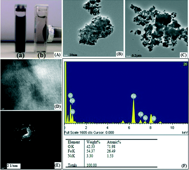
The IO@Ni core–shell NPs were recovered by external magnetic separation (Fig. 6A; a and b) with negligible loss. Recycling experiments carried out under optimized conditions showed interesting results. It was observed that the NPs could be reused directly without further purification for 30 consecutive runs, as can be seen in Table 3, with a very high total turnover number (TTN) of 3456. Up to 16 cycles there was no loss in activity. After that, however, the reaction time increased with each successive recycling experiment from 12 min up to 140 min. This may be due to gradual loss of the catalytic activity of the nanocatalyst with the number of runs, which may be due to various reasons. One of the reasons may be surface modification due to the deposition of matter during the reaction.34 The HR-TEM images of the nanocatalyst recorded after the 30th run display an agglomeration of NPs due to deposited matter (Fig. 6B and C). The image in Fig. 6D shows that lattice fringes were damaged by deposited matter throughout the particle. The SAED pattern shown in Fig. 6E corresponds to the reflections of IO@NiNPs, confirming that the catalyst is still crystalline in nature; however, the catalytic activity reduces due to deposited matter. Nevertheless, the reaction does proceed to completion at the same temperature at the end of 30 cycles giving the same yield. Further, the reused IO@NiNPs were also characterized by EDX and atomic absorption spectrophotometry (AAS) to confirm the leaching of nickel during the reaction. EDX analysis reveals that the Ni content in IO@NiNPs, which was 1.89% before the reaction, showed a marginal decrease to 1.53% (Fig. 6F) after the reusability study of 30 cycles. This confirmed that only negligible leaching of nickel occurred, which was further supported by AAS results (ESI†). Ferrous and ferric ion leaching were also confirmed by AAS (ESI†). The high recyclability and stability of IO@NiNPs can be attributed to the presence of a starch coating which makes the IO@NiNPs stable to water and air and maintains the metallic state of nickel in the catalyst.35 This eventually increases their utility and enhances recycling efficiency. Thus, the metal surface, capping agent and NaBH4 simultaneously make the IO@NiNPs system an effective catalyst.| Cycle | Time (min ±2) | Yielda (±1%) | IYb (±3%) | Cycle | Time (min) | Yielda (±1%) | IYb (±3%) |
|---|---|---|---|---|---|---|---|
| a GC yield. b Isolated yield. | |||||||
| 1 | 12 | 98 | 96 | 16 | 22 | 99 | 96 |
| 2 | 12 | 99 | 96 | 17 | 30 | 98 | 96 |
| 3 | 14 | 98 | 96 | 18 | 36 | 98 | 96 |
| 4 | 13 | 98 | 96 | 19 | 35 | 99 | 95 |
| 5 | 13 | 98 | 96 | 20 | 42 | 99 | 95 |
| 6 | 16 | 98 | 96 | 21 | 45 | 99 | 96 |
| 7 | 15 | 97 | 96 | 22 | 46 | 99 | 96 |
| 8 | 16 | 98 | 96 | 23 | 45 | 99 | 96 |
| 9 | 21 | 98 | 96 | 24 | 45 | 98 | 95 |
| 10 | 25 | 98 | 96 | 25 | 47 | 99 | 96 |
| 11 | 24 | 99 | 96 | 26 | 45 | 98 | 96 |
| 12 | 21 | 99 | 96 | 27 | 44 | 99 | 96 |
| 13 | 25 | 98 | 96 | 28 | 59 | 98 | 96 |
| 14 | 21 | 98 | 96 | 29 | 70 | 98 | 95 |
| 15 | 24 | 98 | 96 | 30 | 140 | 98 | 96 |
Conclusion
The present study demonstrated the feasibility of using a waste from iron ore beneficiation plants (IOTs) as one of the starting materials for the synthesis of IO@Ni core–shell MNPs and their possible application in catalysis. A highly efficient, viable heterogeneous IO@Ni core–shell MNP catalyst was developed for the hydrogenation reaction using the environmentally friendly solvent water. Due to strong interactions between NiNPs and iron oxide, the catalyst could be reused by recycling 30 times without any significant loss in catalytic activity and selectivity. The reaction was broadly applicable as diverse aromatic nitro compounds were successively converted to the corresponding amines in excellent yield (85–96%), high TON and TOF. Being robust and magnetically separable, this core–shell catalyst is a promising candidate for other important organic conversions and industrial applications. Further investigation, modification, and applications are under progress in our laboratory.Experimental
Materials
p-Nitroaniline (PNA), other aromatic nitro compounds, NaBH4, Ni(CH3COO)2·4H2O, liquid ammonia, and starch were purchased from Merck Mumbai, India. All of the solutions were prepared using double-distilled and demineralized water. Iron ore tailings, collected from iron industries (Silverline Exporters Private Limited, Gujarat, India), were screened for their iron content and one sample with relatively high iron content (~36.04%) was used as one of the starting materials.Synthesis of iron oxide
A mixture of iron oxide was synthesized from the waste iron ore tailings (IOTs) via acid leaching and precipitation through a sequential precipitation method, as previously reported.35 For almost complete recovery of iron from IOTs it was first neutralized by adding Ca(OH)2 followed by the settling of aluminium hydroxide and calcium sulfate; subsequently, it was neutralized by adding NaOH followed by precipitation of Fe(OH)2. The Fe(OH)2 was gradually oxidized to iron oxide. The thermal treatment of iron oxide was performed in an oven, after drying at 100 °C, at 450 °C. Further details on the synthesis of iron oxide are discussed elsewhere.36–38 These results indicate that IOTs could be used as a source material for the production of iron oxide, with comparable quality to those produced using analytical-grade reagents.Synthesis of iron oxide@nickel nanoparticles (IO@NiNPs)
IO@Ni core–shell NPs were synthesized by reduction of Ni+ ions in the presence of iron oxide. To deposit NiNPs, 100 mg of iron oxide was dispersed in 10 mL of deionized water and sonicated for 30 min. Nickel nanoparticles were synthesized on magnetic core through a wet chemical reduction process by earlier reported methods with minor modifications.25b Ni(CH3COO)2·4H2O and soluble starch were used as a metal salt precursor and stabilizing agent, respectively. NaBH4 (10%, W/V) was used as a reducing agent and liquid ammonia as a complexing agent. Briefly, 10 mL of 0.02 M nickel acetate solution was added to 10 mL of starch solution (1%, W/V) and stirred on a magnetic stirrer at RT. The pH of the solution was adjusted to 10 with liquid ammonia (600 μL) and reduction was carried out with 200 μL of NaBH4 solution. On further stirring for 10 min, the IO were gradually coated by NiNPs when the colour of the solution changed from red to reddish black. The resultant IO@NiNPs were collected by an external magnet and washed with deionized water several times to remove unreacted materials. Finally, NPs were washed with acetone, and dried at 60 °C under a vacuum.Catalytic reduction of p-nitroaniline and other aromatic nitro compounds
In a typical reaction PNA 50 mg (0.362 mmol) was used as a starting material, NaBH4 54.6 mg (1.44 mmol) as a source of hydrogen, water (2 mL) as a solvent and IO@Ni-MNPs 12 mg (0.45 wt% NiNPs of PNA) as a nanocatalyst. All the components were mixed together in a 10 mL round-bottom flask and the reaction was carried out at room temperature (rt, 25–30 °C) under stirring for 12 min. Reaction monitoring was done by thin-layer chromatography (TLC) and gas chromatography. After completion of the reaction, the catalyst was separated magnetically. The product was isolated by extraction in dichloromethane, and evaporation of solvent followed by column chromatography (10![[thin space (1/6-em)]](https://www.rsc.org/images/entities/char_2009.gif) :
:![[thin space (1/6-em)]](https://www.rsc.org/images/entities/char_2009.gif) 90, ethyl acetate in hexane v/v) over basic alumina furnished p-phenylenediamine (PPDA). The spectroscopic data of this compound are in good agreement with those reported. The reaction was also carried out with IO, NiNPs and without catalyst for comparison.
90, ethyl acetate in hexane v/v) over basic alumina furnished p-phenylenediamine (PPDA). The spectroscopic data of this compound are in good agreement with those reported. The reaction was also carried out with IO, NiNPs and without catalyst for comparison.
Reduction of other nitro aromatics was carried out in a similar manner. The products purified by short-path basic alumina chromatography (0–40% ethyl acetate in hexane v/v) were analyzed by 1H NMR (ESI†).
All experiments have been repeated three times and the reproducibility confirmed. The recyclability of the NPs was also surveyed. The NPs were recovered with a magnet and washed with water followed by methanol and again with water. They were dried at 60 °C under vacuum and used for the next cycle.
Characterization methods
The chemical analyses for the major constituents of IOT, acid insoluble residue and aqueous suspension of IO@NiNPs were carried out by conventional wet chemical analysis while AAS (AA 6300: Shimadzu, Japan) or ICP-OES (Perkin Elmer, 4300) was used to analyze the constituents present in traces. The powdered X-ray diffraction (XRD) patterns were recorded with a PanAlytical (model; Empyrean) ‘X’PERT-PRO XRPD with Cu Kα radiation (λ = 0.15406 nm) on an advance X-ray powder diffractometer. Samples were prepared by pressing dried powder and patterns were collected with a scanning rate of 2° min−1 and 2θ ranging from 0 to 80°. Surface area and porosity of the nanocatalyst were measured by a volumetric adsorption system (Micromeritics Instrument corporation, USA, model ASAP 2010) using N2 adsorption/desorption isotherms at 77 K up to 1 bar. Prior to the measurements, the samples were activated (degassed) by heating at the rate of 1 K min−1 up to 383 K under vacuum. The temperature as well as vacuum were maintained for 7 hours prior to the measurements. Surface area was calculated by the Brunauer–Emmet–Teller (BET) method and the porosity by the Barrett–Joyner–Halenda (BJH) method. High-Resolution Transmission Electron Microscopy (HR-TEM) was carried out using a Jeol (Jem-2100) electron microscope operated at an acceleration voltage of 200 kV. For this purpose, the dry powered sample was dispersed in methanol and ultrasonication treatment was carried out for 30 min. Subsequently, that sample was deposited onto a carbon-coated grid at room temperature and it was allowed to air dry (about 6 hours). Selected area electron diffraction patterns (SAED) and Energy-dispersive X-ray spectroscopy (EDX/EDS) were also investigated from the electron micrographs. FT-IR spectra were recorded with KBr pellets on a Perkin Elmer RX1 model in the range of 4000–400 cm−1. Magnetic measurements were done by a vibrating sample magnetometer (EG&G Model 155 VSM) at room temperature in the range +20![[thin space (1/6-em)]](https://www.rsc.org/images/entities/char_2009.gif) 000 to −20
000 to −20![[thin space (1/6-em)]](https://www.rsc.org/images/entities/char_2009.gif) 000 G. The surface composition was investigated using X-ray photoelectron spectroscopy (XPS) on a VSW X-ray photoelectron spectrometer (UK) using a Mg and Al twin anode X-ray gun with multichannel detector and hemispherical analyser having resolution of 1.0 eV. The binding energies obtained in the XPS analysis were calibrated against the C1s peak at 284.6 eV.
000 G. The surface composition was investigated using X-ray photoelectron spectroscopy (XPS) on a VSW X-ray photoelectron spectrometer (UK) using a Mg and Al twin anode X-ray gun with multichannel detector and hemispherical analyser having resolution of 1.0 eV. The binding energies obtained in the XPS analysis were calibrated against the C1s peak at 284.6 eV.
IO@NiNPs-catalyzed hydrogenation reactions were monitored on a PerkinElmer Lambda 35 UV-vis spectrophotometer by corresponding λmax. Hydrogenation reaction monitoring was also done by thin-layer chromatography (TLC, using ninhydrin as staining reagent) and gas chromatography (GC). All products of the reduction of nitroarenes are commercially available and were identified by comparing their physical and spectral data (m.p., TLC (silica gel 60 F254, Merck, Mumbai, India), GC (Perkin Elmer clarus 500 GC) and 1H NMR (BRUKER 400 MHz)) with those of authentic samples or reported data.
Acknowledgements
The authors are grateful to the Solvay group, Research, Development and Technology Centre at Savli, Gujarat, India, for financial assistance.References
-
(a)
P. T. Anastas and J. C. Warner, Green Chemistry Theory and Practice, Oxford University Press, Oxford, 1998 Search PubMed
; (b) A. S. Matlack, Introduction to Green Chemistry, Marcel Dekker, New York, 2001 Search PubMed
; (c) J. H. Clark and D. J. Macquarrie, Handbook of Green Chemistry and Technology, Blackwell Publishing, Abingdon, 2002 Search PubMed
; (d) V. Polshettiwar and R. S. Varma, Chem. Soc. Rev., 2008, 37, 1546 RSC
.
-
(a)
V. Polshettiwar and R. S. Varma, Aqueous Microwave Chemistry, RSC Publishing, Cambridge, 2010 Search PubMed
; (b) V. Polshettiwar and R. S. Varma, Acc. Chem. Res., 2008, 41, 629 CrossRef CAS PubMed
; (c) R. B. N. Baig and R. S. Varma, Chem. Commun., 2012, 48, 5853 RSC
; (d) R. B. N. Baig and R. S. Varma, Chem. Soc. Rev., 2012, 41, 1559 RSC
.
-
(a) S. Wittmann, A. Shatz, R. N. Grass, W. J. Stark and O. Reiser, Angew. Chem., Int. Ed., 2010, 49, 1867 CrossRef CAS PubMed
; (b) M. Benaglia, Recoverable and Recyclable Catalysts, John Wiley & Sons, Chichester, 2009 Search PubMed
; (c) V. Polshettiwar and R. S. Varma, Green Chem., 2010, 12, 743 RSC
.
-
(a) F. Alonso, P. Riente and M. Yus, Acc. Chem. Res., 2011, 44, 379 CrossRef CAS PubMed
; (b) F. Alonso and M. Yus, Pure Appl. Chem., 2008, 80, 1005 CrossRef CAS
; (c) N. Yan, C. Xiao and Y. Kou, Coord. Chem. Rev., 2010, 254, 1179 CrossRef CAS PubMed
; (d) S. Shylesh, V. Schnemann and W. R. Thiel, Angew. Chem., Int. Ed., 2010, 49, 3428 CrossRef CAS PubMed
; (e) V. Polshettiwar, R. Luque, A. Fihri, H. Zhu, M. Bouhrara and J.-M. Basset, Chem. Rev., 2011, 111, 3036 CrossRef CAS PubMed
.
-
(a) R. B. N. Baig and R. S. Varma, Chem. Commun., 2013, 49, 752 RSC
; (b) V. Polshettiwar and R. S. Varma, Green Chem., 2010, 12, 743–754 RSC
.
-
(a) T. Hirakawa and P. V. Kamat, J. Am. Chem. Soc., 2005, 127, 3928 CrossRef CAS PubMed
; (b) Y. J. Huang, X. C. Zhou, M. Yin, C. P. Liu and W. Xing, Chem. Mater., 2010, 22, 5122 CrossRef CAS
; (c) J. X. Wang, H. Inada, L. J. Wu, Y. M. Zhu, Y. M. Choi, P. Liu, W. P. Zhou and R. R. Adzic, J. Am. Chem. Soc., 2009, 131, 17298 CrossRef CAS PubMed
; (d) K. Bakhmutsky, N. L. Wieder, M. Cargnello, B. Galloway, P. Fornasiero and R. J. Gorte, ChemSusChem, 2012, 5, 140 CrossRef CAS PubMed
; (e) H. L. Jiang, T. Akita and Q. Xu, Chem. Commun., 2011, 47, 10999 RSC
; (f) J. Bao, J. He, Y. Zhang, Y. Yoneyama and N. Tsubaki, Angew. Chem., Int. Ed., 2008, 47, 353 CrossRef CAS PubMed
; (g) H. L. Jiang, T. Akita, T. Ishida, M. Haruta and Q. Xu, J. Am. Chem. Soc., 2011, 133, 1304 CrossRef CAS PubMed
; (h) R. G. Chaudhuri and S. Paria, Chem. Rev., 2012, 112, 2373 CrossRef PubMed
, and references cited therein.
- M. B. Gawande, H. Guo, A. K. Rathi, P. S. Branco, Y. Chen, R. S. Varma and D.-L. Peng, RSC Adv., 2013, 3, 1050 RSC
, and references cited therein.
- V. Polshettiwar, R. Luque, A. Fihri, H. Zhu, M. Bouhrara and J.-M. Basset, Chem. Rev., 2011, 111, 3036 CrossRef CAS PubMed
.
- P. S. Haddad, T. M. Martins, L. D. Souza-Li, L. M. Li, K. Metze, R. L. Adam, M. Knobel and D. Zanchet, Mater. Sci. Eng., C, 2008, 28, 489–494 CrossRef CAS PubMed
.
- S. Si, A. Kotal, T. K. Mandal, S. Giri, H. Nakamura and T. Kohara, Chem. Mater., 2004, 16, 3489 CrossRef CAS
.
- A. Zablotskaya, I. Segal, E. Lukevics, M. Maiorov, D. Zablotsky, E. Blums, I. Shestakova and I. Domracheva, J. Magn. Magn. Mater., 2009, 321, 1428 CrossRef CAS PubMed
.
- W. Cai and J. Wan, J. Colloid Interface Sci., 2007, 30, 366 CrossRef PubMed
.
- D. Maity and D. C. Agrawal, J. Magn. Magn. Mater., 2007, 308, 46 CrossRef CAS PubMed
.
- S. K. Das, S. Kumar and P. Ramachandrarao, Waste Manage., 2000, 20, 725 CrossRef CAS
.
- H. Yu, X. Xue and D. Huang, Mater. Res. Bull., 2009, 44, 2112 CrossRef CAS PubMed
.
- C. Li, H. Sun, Z. Yi and L. Li, J. Hazard. Mater., 2010, 174, 78 CrossRef CAS PubMed
.
- L. Zeng, X. Li and J. Liu, Water Res., 2004, 38, 1318 CrossRef CAS PubMed
.
- S. Zhang, S. Xue, X. Liu, P. Duan, H. Yang, T. Jiang, D. Wang and R. Liu, J. Min. Sci., 2006, 42, 403 CrossRef PubMed
.
- S. K. Giri, N. N. Das and G. C. Pradhana, Colloids Surf., A, 2011, 389, 43 CrossRef CAS PubMed
.
-
(a) A. M. Tafesh and J. Weiguny, Chem. Rev., 1996, 96, 2035 CrossRef CAS PubMed
; (b) R. J. Rahaim, Jr. and R. E. Maleczka, Jr., Org. Lett., 2005, 7, 5087 CrossRef PubMed
; (c) S. Chandrasekhar, S. J. Prakash and C. L. Rao, J. Org. Chem., 2006, 71, 2196 CrossRef CAS PubMed
; (d) Q. Shi, R. Lu, L. Lu, X. Fu and D. Zhao, Adv. Synth. Catal., 2007, 349, 1877 CrossRef CAS PubMed
.
-
(a) C. Yu, B. Liu and L. Hu, J. Org. Chem., 2001, 66, 919–924 CrossRef CAS
, and references therein; (b) A. K. Shil and P. Das, Green Chem., 2013, 15, 3421 RSC
.
- A. Saha and B. Ranu, J. Org. Chem., 2008, 73, 6867 CrossRef CAS PubMed
and references therein.
- A. Corma and P. Serna, Science, 2006, 313, 332 CrossRef CAS PubMed
.
-
(a) N. Sahiner, S. Butun and P. Ilgin, Colloids Surf., A, 2011, 386, 16 CrossRef CAS PubMed
; (b) M. B. Gawande, A. K. Rathi, P. S. Branco, I. D. Nogueira, A. Velhinho, J. J. Shrikhande, U. U. Indulkar, R. V. Jayaram, C. A. A. Ghumman, N. Bundaleski and O. M. N. D. Teodoro, Chem. – Eur. J., 2012, 18, 12628 CrossRef CAS PubMed
; (c) R. Dey, N. Mukherjee, S. Ahammed and B. C. Ranu, Chem. Commun., 2012, 48, 7982 RSC
.
-
(a) P. S. Rathore, J. Advani, S. Rathore and S. Thakore, J. Mol. Catal. A: Chem., 2013, 377, 129 CrossRef CAS PubMed
; (b) P. S. Rathore, R. Patidar, S. Rathore and S. Thakore, Catal. Lett., 2014, 144, 439 CrossRef CAS PubMed
.
- W. Kim, C.-Y. Suh, S.-W. Cho, K.-M. Roh, H. Kwon, K. Song and I.-J. Shon, Talanta, 2012, 94, 348 CrossRef CAS PubMed
.
- Y. Ren, R. Cingolani, R. Buonsanti, P. D. Cozzoli and V. Petkov, J. Am. Chem. Soc., 2009, 131, 14264 CrossRef PubMed
.
- N. Kimizuka, S. Sasaki and K. Tsukimura, Jpn. J. Appl. Phys., Part 1, 1997, 36, 3609 CrossRef
.
- A. P. Grosvenor, M. C. Biesinger, R. St, C. Smart and N. S. McIntrye, Surf. Sci., 2006, 600, 1771 CrossRef CAS PubMed
.
- D. Maiti, U. Manju, S. Velaga and P. S. Devi, Cryst. Growth Des., 2013, 13, 3637 CAS
.
-
(a) X. Huang, X. Liao and B. Shi, Green Chem., 2011, 13, 2801 RSC
; (b) P. Hervés, M. Pérez-Lorenzo, L. M. Liz-Marzán, J. Dzubiella, Y. Lu and M. Ballauff, Chem. Soc. Rev., 2012, 41, 5577 RSC
.
- Z. Jiang, J. Xie, D. Jiang, X. Wei and M. Chen, CrystEngComm, 2013, 15, 560–569 RSC
.
- Y. Kojima and T. Haga, Int. J. Hydrogen Energy, 2003, 28, 989 CrossRef CAS
.
-
(a)
J. J. Spivey, G. W. Roberts and B. H. Davies, Catalyst Deactivation, Elsevier, Amsterdam, 2001 Search PubMed
; (b) F. Alonso, P. Riente, J. A. Sirvent and M. Yus, Appl. Catal., A, 2010, 378, 42 CrossRef CAS PubMed
.
-
(a) M. Valodkar, P. S. Rathore, R. N. Jadeja, M. Thounaojam, R. V. Devkar and S. Thakore, J. Hazard. Mater., 2012, 201–202, 244 CrossRef CAS PubMed
; (b) J. M. Yan, X. B. Zhang, S. Han, H. Shioyama and Q. Xu, Inorg. Chem., 2009, 48, 7389 CrossRef CAS PubMed
.
-
V. S. Madeira, Coal Mine Residues Recycling for the Fabrication of High Added Value Products, Ph.D. thesis, Federal University of Santa Catarina, Brazil (in Portuguese), 2010 Search PubMed
.
- S. L. F. Andersen, R. G. Flores, V. S. Madeira, H. J. José and R. F. P. M. Moreira, Ind. Eng. Chem. Res., 2012, 51, 767 CrossRef
.
- R. G. Flores, S. L. F. Andersen, L. K. K. Maia, H. J. José and R. F. P. M. Moreira, J. Environ. Manage., 2012, 111, 53 CrossRef CAS PubMed
.
Footnote |
| † Electronic supplementary information (ESI) available. See DOI: 10.1039/c4cy00673a |
| This journal is © The Royal Society of Chemistry 2015 |

