 Open Access Article
Creative Commons Attribution 3.0 Unported Licence
Solvent-free iridium-catalyzed CO2 hydrosilylation: experiments and kinetic modeling†
E. A.
Jaseer
a,
Muhammad N.
Akhtar
a,
Mogahid
Osman
a,
A.
Al-Shammari
a,
Habeebllah B.
Oladipo
a,
Karin
Garcés
b,
Francisco J.
Fernández-Alvarez
*b,
Sulaiman
Al-Khattaf
*a and
Luis A.
Oro
*ab
aCenter of Research Excellence in Petroleum Refining & Petrochemicals, King Fahd University of Petroleum & Minerals, 31261 Dhahran, Saudi Arabia. E-mail: skhattaf@kfupm.edu.sa
bDepartamento de Química Inorgánica, Instituto de Síntesis Química y Catálisis Homogénea (ISQCH), Universidad de Zaragoza-CSIC, Facultad de Ciencias 50009, Zaragoza, Spain. E-mail: oro@unizar.es; paco@unizar.es
First published on 30th July 2014
Abstract
The iridium(III) complex [Ir(H)(CF3SO3)(NSiN)(coe)] (NSiN = bis(pyridine-2-yloxy)methylsilyl, coe = cyclooctene) has been demonstrated to be an active catalyst for the solvent-free hydrosilylation of CO2 with 1,1,1,3,5,5,5-heptamethyltrisiloxane (HMTS) under mild reaction conditions (3 bar). The activity of this catalytic system depends on the reaction temperature. The best catalytic performance has been achieved at 75 °C. A kinetic study at variable temperature (from 25 °C to 75 °C) and constant pressure (3 bar) together with kinetic modeling has been carried out. The results from such a study show an activation energy of 73.8 kJ mol−1 for the process.
1. Introduction
The development of sustainable processes for carbon dioxide (CO2) reduction is a topic of general interest for the scientific community.1 In particular, catalytic CO2 hydrosilylation represents a thermodynamically favorable process for the transformation of CO2 into value-added chemicals,2 which also presents the advantages that some hydrosilanes are easy to handle, readily available and environmentally harmless.3 This CO2 fixation method allows formation of silylformates which have been successfully used as C1 building blocks in the synthesis of formic acid,4 formamides,5 amines,6 and methane.7 Selectivity is a relevant parameter to take into account when new catalysts for CO2 hydrosilylation to silylformates have to be designed. This is due to the reactivity of silylformates, which under the reaction conditions could be hydrosilylated to afford the corresponding bis(silyl)acetal, which could react further with excess hydrosilane present in the reaction mixture to give methoxysilane and (R3Si)2O (Scheme 1).8 Additionally, the reaction of the corresponding methoxysilane with one additional equivalent of hydrosilane could lead to the formation of methane and (R3Si)2O (Scheme 1).7 It is worth mentioning that some examples of transition metal catalysts as well as organocatalysts which selectively catalyze the hydrosilylation of CO2 to silylformates have been recently reported.4b,9–12 Among them, the phosphane–copper catalysts, using 1,4-dioxane as solvent, reported by Baba and co-workers are the most active known so far.4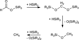 | ||
| Scheme 1 Possible transformations of in situ generated silylformate during catalytic CO2 hydrosilylation processes. | ||
On the other hand, the large-scale use of volatile organic solvents in industrial processes contributes to the impact of human activity on the environment.13,14 Therefore, the development of solvent-free synthetic and catalytic processes has become of wide interest for chemists.15 To the best of our knowledge only two solvent-free catalytic systems effective for the hydrosilylation of CO2 to silylformate have been reported.12,16
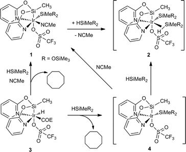
In this context, it has been previously communicated that the complex [Ir{SiMe(OSiMe3)2}(CF3SO3)(NSiN)(NCMe)] (1) (NSiN = bis(pyridine-2-yloxy)methylsilyl, coe = cyclooctene) catalyzes the selective formation of silylformate by solvent-free hydrosilylation of CO2 with 1,1,1,3,5,5,5-heptamethyltrisiloxane (HMTS) under mild reaction conditions (r.t. and 3 bar). Using complex 1 as the catalyst precursor, an activation step consisting of the replacement of the acetonitrile molecule by one molecule of HMTS to yield the corresponding active intermediate 2 containing a η2-(H–Si) coordinated HMTS molecule is required (Scheme 2).16 Theoretical studies at the DFT level showed that the Si–H bond activation is a triflate ligand-assisted process viaTS-1 and that the activation of the CO2 molecule proceeds via an outer-sphere mechanism through the transition state TS-2 (Scheme 3).16
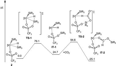 | ||
| Scheme 3 Energy profile for the outer-sphere mechanism of the hydrosilylation of CO2 using complex 1 as the catalyst precursor ([Ir] = Ir(NSiN); R = Me; energy is in kJ mol−1). | ||
It is worth noting that the yield of the reaction of the synthesis of 1 from 3 (Scheme 2) is relatively low due to purification difficulties. Subsequently, the use of an alternative catalyst precursor is of interest. In this regard, preliminary 1H NMR studies of the reaction of 3 with HMTS in CD2Cl2 in the absence of acetonitrile showed the formation of cyclooctane together with a mixture of unidentified iridium-containing compounds. Interestingly, when the same reaction was carried out using a mixture of acetonitrile-d3 and CD2Cl2 as solvents 1H NMR studies evidenced the formation of cyclooctane and 1 (see the ESI†). These results are consistent with the formation of intermediate 4 which coordinates a molecule of acetonitrile to give 1 (Scheme 2). Therefore, it is reasonable to assume that under solvent-free conditions, complex 3 could afford directly the active species 2via η2-(H–Si) coordination of a molecule of silane to 4.
The aforementioned background motivates us to explore the potential application of compound 3 as a catalyst precursor in solvent-free CO2 hydrosilylation processes. Herein, we report a detailed kinetic study at variable temperature together with kinetic modeling of the catalytic hydrosilylation of CO2 with 1,1,1,3,5,5,5-heptamethyltrisiloxane (HMTS) using complex 3 as a catalyst precursor.
2. Experimental
General information
All manipulations were performed with rigorous exclusion of air at an argon/vacuum manifold using standard Schlenk-tube techniques or in a dry box (MB-UNILAB). Catalytic experiments were carried out using a 25 mL Teflon-lined batch reactor. Gas chromatography-mass spectrometry (GC-MS) analyses were performed using an Agilent 7890A GC system, an Agilent 5975C inert MSD with a Triple-Axis Detector MS system, and an HP5-MS capillary column (30 m × 250 μm, film thickness 0.25 μm). Oven parameters: an initial temperature of 45 °C was held for 1.0 min, and then the temperature was increased up to 160 °C at a heating rate of 8.0 °C min−1 and held for 1.0 min, then heated up again to 250 °C at a rate of 8.0 °C min−1. Carrier gas flow was 1.2 mL min−1 and the injection volume was 0.1 mL. Inlet temperature was 250 °C and the split ratio was 100![[thin space (1/6-em)]](https://www.rsc.org/images/entities/char_2009.gif) :
:![[thin space (1/6-em)]](https://www.rsc.org/images/entities/char_2009.gif) 1. The iridium(III) complex 3 was prepared according to a method reported in the literature.16 NMR spectra were recorded on a Bruker ARX 300 or a Bruker Avance 300 MHz spectrometer. Chemical shifts (expressed in parts per million) were referenced to residual solvent peaks (1H, 13C{1H}). Coupling constants, J, were given in Hertz. 1,1,1,3,5,5,5-Heptamethyltrisiloxane (HMTS) and carbon dioxide (99.99 purity) were purchased from commercial sources. HMTS was dried over 4Å molecular sieves.
1. The iridium(III) complex 3 was prepared according to a method reported in the literature.16 NMR spectra were recorded on a Bruker ARX 300 or a Bruker Avance 300 MHz spectrometer. Chemical shifts (expressed in parts per million) were referenced to residual solvent peaks (1H, 13C{1H}). Coupling constants, J, were given in Hertz. 1,1,1,3,5,5,5-Heptamethyltrisiloxane (HMTS) and carbon dioxide (99.99 purity) were purchased from commercial sources. HMTS was dried over 4Å molecular sieves.
Catalytic reactions at variable temperature and 3 bar
A 25 mL Teflon-lined batch reactor with Teflon lining inside was charged with dry HMTS (3 mL, 11.04 mmol). Then the reactor was closed, purged with CO2 gas a few times and heated to the corresponding temperature. After stabilization to the corresponding temperature, the reactor was opened under argon and the iridium catalyst 3 (75 mg, 0.11 mmol), which was weighed in a glove box, was added. After closing the reactor, the system was purged a few times using vacuum and CO2 gas. Then the pressure of CO2 gas was adjusted to 3 bar. The liquid samples were taken periodically after releasing the CO2 pressure, without opening the reactor, using a long needle through the sample withdrawal valve. The reactor was purged with vacuum and CO2 several times after each sample withdrawal and pressure was returned to 3 bar using CO2. For GC-MS sample preparation, the collected samples were diluted in dry tetrahydrofuran (0.5 mL) and analyzed by quantifiable GC-MS. The product yield was obtained by comparison of the area corresponding to the peaks assigned to the reaction products with the area of the peak corresponding to HMTS.Kinetic modeling of the catalytic reaction
A power law model was proposed as a descriptor of the kinetics of the first-order reaction17 of CO2 with HMTS. The rate of the disappearance of HMTS (eqn (1)) and the rate of the formation of silylformate (eqn (2)) can be written as: | (1) |
 | (2) |
3. Results and discussion
Reaction of CO2 with HMTS at 298 K using catalytic amounts of 3
We have found that the catalytic solvent-free reaction of CO2 (298 K, 3.0 bar) with HMTS to produce the corresponding silylformate was faster when complex 3 (1.0 mol%) was used instead of 1 as the catalyst precursor. Indeed, using complex 3, the total consumption of HMTS to give a yellow oil identified by 1H, 29Si{1H} NMR spectroscopy and GC-MS as a silylformate, HCOOSiMe(OSiMe3)2, (in approximately 89% yield) was observed after three and a half days of reaction, while 6 days were needed to achieve full conversion of HMTS using complex 1 (1.0 mol%) as the catalyst precursor under the same reaction conditions.1H NMR spectra of CD2Cl2 solutions of the reaction mixture confirm that at the end of the reaction HCOOSiMe(OSiMe3)2 is the major reaction product (see the ESI†). Interestingly, in these spectra we always observed the presence of a minor resonance at δ 1.54 ppm which shows a direct C–H bond correlation in the heteronuclear single quantum correlation (HSQC) with one signal that appears at δ 27.3 ppm in the 13C{1H} NMR spectra of the reaction samples and subsequently has been assigned to the CH2 moieties of cyclooctane. The formation of cyclooctane supports that the in situ generation of the active species 2 by reaction of 3 with HMTS could be proposed as the activation step of the catalytic process (Scheme 2). Furthermore, 29Si{1H} NMR spectra of CD2Cl2 solutions of the reaction product also confirm the formation of HCOOSiMe(OSiMe3)2 as the major reaction product. These spectra show two single resonances at δ 11.0 ppm and at δ −58.4 ppm corresponding to the OSiMe3 and HCOOSiMe silicon atoms, respectively.16,20 Additionally, traces of other unidentified silicon-containing minor species were observed (see Fig. 1 and S8 in the ESI†).
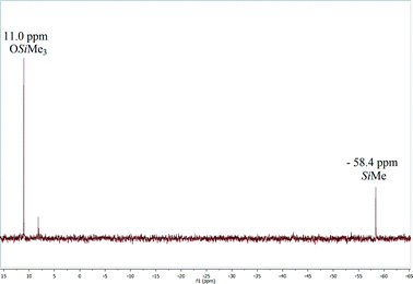 | ||
| Fig. 1 29Si{1H} NMR (79.5 MHz, CD2Cl2) spectrum of the product of the reaction of CO2 (3 bar) with HMTS after 3.5 days at 25 °C using 3 (1.0 mol%) as the precatalyst. | ||
GC-MS spectra of the reaction samples taken after 3.5 days of reaction at 25 °C evidenced the full consumption of the starting HMTS and the presence of a peak with a retention time of 7.74 min corresponding to a major reaction product (close to 89% yield) (Fig. 2 and Table 1). The mass pattern found for that peak agrees with that expected for HCOOSiMe(OSiMe3)2 (see the ESI†). An additional peak due to {(Me3SiO)2MeSi}2O appears at 14.02 min (9.4%). The presence of {(Me3SiO)2MeSi}2O could be attributable to further reactions of silylformate and its derivatives with HMTS under the reaction conditions21 (Scheme 1) or to some iridium-catalyzed hydrolysis of the starting hydrosilane.22
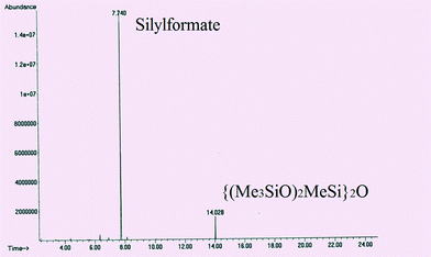 | ||
| Fig. 2 GC profile of the product of the reaction of CO2 (3 bar) with HMTS after 3.5 days at 25 °C using 3 (1.0 mol%) as the precatyst. | ||
These results compare well with the work reported by Mizuno and co-workers using the catalytic system [Rh2(OAc)4] (0.25 mol%)/K2CO3.10
Kinetic study of the catalytic hydrosilylation of CO2 with HMTS
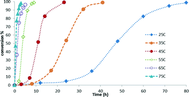
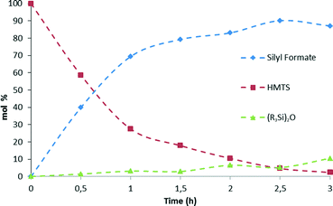
Kinetic studies of the reaction of hydrosilylation of CO2 with 1,1,1,3,5,5,5-heptamethyltrisiloxane (HMTS) in the presence of a catalytic amount of 3 (1.0 mol%) show that the rate of this process is temperature dependent. The results from the kinetic studies of the reaction are depicted in Fig. 3. The points in Fig. 3 represent the conversion of HMTS versus time. The dotted lines in Fig. 3 have no mathematical meaning and uniquely represent a continuous path between the experimental data points. These results evidenced that increasing the temperature of the reactor from 25 °C to 75 °C enhances the catalytic activity.A higher catalytic activity was found at 75 °C. GC-MS studies of the reaction evidenced that after 3 hours at that temperature most of the starting HMTS has been consumed and HCOOSiMe(OSiMe3)2 (87.0%) is the major reaction product together with traces of {(Me3SiO)2MeSi}2O (Fig. 4 and Table 1).
Table 1 shows that at temperatures higher than 45 °C there is a slight fall-off of the reaction yield. In addition, it has been observed that at these temperatures the silylformate is partially transformed into {(Me3SiO)2MeSi}2O (see Fig. 4 and Table S1 in the ESI†). This observation agrees with the known reactivity of silylformates (see Scheme 1).21
The catalytic activity found for 3 in this work is higher than that previously reported for complex 1 and compares well with the catalytic activity of the zinc-based catalytic system reported by Sattler and Parkin for the solvent-free hydrosilylation of CO2 with HSi(OEt)3.12 In addition, complex 3 shows better catalytic activity in the range of 55 °C and 75 °C (Table 1).
Kinetic modeling of the Ir-catalyzed CO2 hydrosilylation
Kinetic modeling of the iridium-catalyzed hydrosilylation of CO2 with HMTS has been developed based on the chemical equation presented in Scheme 4 and on the approximation that the rate of disappearance of HMTS (eqn (1)) is equal in absolute terms but opposite in sign to the rate of the formation of HCOOSiMe(OSiMe3)2 (eqn (2)). | ||
| Scheme 4 Solvent-free catalytic CO2 hydrosilylation with HMTS using 3 (1.0 mol%) as the catalyst precursor. | ||
A power law model17 was proposed as a descriptor of the kinetics of the first-order reaction shown in Scheme 4. The reaction rate constants are supposed to be related to temperature through the Arrhenius equation.18 The mole balance equations (eqn (1) and (2)) incorporating the Arrhenius relation between ki and Ea (see the ESI†) were evaluated by least-squares fitting of the kinetic parameters using the experimental data obtained from the GC-MS studies of the reaction of hydrosilylation of CO2 with HMTS using 3 (1.0 mol%) as a precatalyst at different temperatures (see the ESI†). Experimental data were used to optimize the model parameters. In order to select the acceptable model the following criteria were considered. All of the kinetic parameters (specific reaction rates and activation energies) should be consistent with (i) physical principles, (ii) coefficient of determination (R2), (iii) lower SSR (sum of the squares of the residuals), (iv) lower cross-correlation coefficient (γ), and (v) lower individual confidence intervals for the model parameters.
As a result of this, kinetic study values of 73.8 (±2.9) kJ mol−1 and of 3.1 10−2 (±0.03) s−1 have been found for the activation energy of the process (Ea) and for the Arrhenius pre-exponential factor, respectively. This Ea value is consistent with the activation energy theoretically calculated at the DFT level for the outer-sphere mechanism proposed in Scheme 3.16
A comparison of the experimental data with the model predictions is plotted in Fig. 5. The temperature dependence of the consumption of HMTS predicted by our model (the continuous lines in Fig. 5) fits in an excellent manner with the experimental data obtained from the GC-MS studies of the reaction samples (data points in Fig. 5).
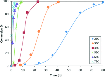 | ||
| Fig. 5 Temperature dependence of the consumption of HMTS predicted by the kinetic model (continuous lines). HMTS conversion obtained from GC-MS experiments (points). | ||
4. Conclusions
The iridium(III) complex [Ir(H)(CF3SO3)(NSiN)(coe)] (3) (NSiN = bis(pyridine-2-yloxy)methylsilyl, coe = cyclooctene) has been demonstrated to be an active catalyst precursor for the solvent-free hydrosilylation of CO2 with 1,1,1,3,5,5,5-heptamethyltrisiloxane (HMTS) under mild reaction conditions (25 °C to 75 °C and 3 bar) allowing preparation of the corresponding silylformate on the gram scale and in high yields. The best catalytic performance has been achieved at 75 °C (TOF = 29.1 h−1). A kinetic study at variable temperature together with kinetic modeling of the catalytic hydrosilylation of CO2 with HMTS using complex 3 as a catalyst precursor has been carried out. The results from this study showed an Ea (activation energy) value of 73.8 kJ mol−1 for this process.Acknowledgements
The authors express their appreciation to the Ministry of Higher Education, Saudi Arabia, for the establishment of the Center of Research Excellence in Petroleum Refining & Petrochemicals at King Fahd University of Petroleum & Minerals (KFUPM) and the KFUPM-University of Zaragoza research agreement for their support. Financial support from MINECO/FEDER (projects CONSOLIDER INGENIO-2010 MULTICAT CSD2009-00050 and CTQ2011-27593) and DGA/FSE (group E07) is also acknowledged. Dr. F. J. Fernández-Alvarez thanks Dr. Ralte Lalrempuia for preliminary investigations.Notes and references
- See for some recent examples; (a) P. G. Jessop, F. Joó and C.-C. Tai, Coord. Chem. Rev., 2004, 248, 2425–2442 CrossRef CAS PubMed; (b) M. Aresta and A. Dibenedetto, Dalton Trans., 2007, 2975–2992 RSC; (c) M. Peters, B. Köhler, W. Kuckshinrichs, W. Leitner, P. Markewitz and T. E. Müller, ChemSusChem, 2011, 4, 1216–1240 CrossRef CAS PubMed; (d) I. Omae, Coord. Chem. Rev., 2012, 256, 1384–1405 CrossRef CAS PubMed; (e) F. J. Fernández-Alvarez, M. Iglesias, L. A. Oro and V. Polo, ChemCatChem, 2013, 5, 3481–3494 CrossRef PubMed; (f) M. Aresta, A. Dibenedetto and A. Angelini, Chem. Rev., 2014, 114, 1709–1742 CrossRef CAS PubMed; (g) T. Fujihara, K. Semba, J. Terao and Y. Tsuji, Catal. Sci. Technol., 2014, 4, 1699–1709 RSC; (h) C. Maeda, Y. Miyazaki and T. Ema, Catal. Sci. Technol., 2014, 4, 1482–1497 RSC; (i) Y.-N. Li, R. Ma, L.-N. He and Z.-F. Diao, Catal. Sci. Technol., 2014, 4, 1498–1512 RSC; (j) A. W. Kleij, Catal. Sci. Technol., 2014, 4, 1481–1481 RSC.
- (a) F. J. Fernández-Alvarez, A. M. Aitani and L. A. Oro, Catal. Sci. Technol., 2014, 4, 611–624 RSC; (b) W. Sattler and G. Parkin, Catal. Sci. Technol., 2014, 4, 1578–1584 RSC.
- (a) N. J. Lawrence, M. D. Drew and S. M. Bushell, J. Chem. Soc., Perkin Trans. 1, 1999, 1, 3381–3391 RSC; (b) W.-S. Han, T.-J. Kim, S.-K. Kim, Y. Kim, Y. Kim, S.-W. Nam and S. O. Kang, Int. J. Hydrogen Energy, 2011, 36, 12305–12312 CrossRef CAS PubMed.
- (a) K. Motokura, D. Kashiwame, A. Miyaji and T. Baba, Org. Lett., 2012, 14, 2642–2645 CrossRef CAS PubMed; (b) K. Motokura, D. Kashiwame, N. Takahashi, A. Miyaji and T. Baba, Chem. – Eur. J., 2013, 19, 10030–10037 CrossRef CAS PubMed.
- (a) O. Jacquet, C. Das Neves Gomes, M. Ephritikhine and T. Cantat, ChemCatChem, 2013, 5, 117–120 CrossRef CAS PubMed; (b) C. Das Neves Gomes, O. Jacquet, C. Villiers, P. Thuéry, M. Ephritikhine and T. Cantat, Angew. Chem., Int. Ed., 2012, 51, 187–190 CrossRef CAS PubMed; (c) O. Jacquet, C. Das Neves Gomes, M. Ephritikhine and T. Cantat, J. Am. Chem. Soc., 2012, 134, 2934–2937 CrossRef CAS PubMed; (d) X. Frogneux, O. Jacquet and T. Cantat, Catal. Sci. Technol., 2014, 4, 1529–1533 RSC.
- (a) Y. Li, X. Fang, K. Junge and M. Beller, Angew. Chem., Int. Ed., 2013, 52, 9568–9571 CrossRef CAS PubMed; (b) O. Jacquet, X. Frogneux, C. Das Neves Gomes and T. Cantat, Chem. Sci., 2013, 4, 2127–2131 RSC.
- (a) S. Park, D. Bézier and M. Brookhart, J. Am. Chem. Soc., 2012, 134, 11404–11407 CrossRef CAS PubMed; (b) A. Berkefeld, W. E. Piers and M. Parvez, J. Am. Chem. Soc., 2010, 132, 10660–10661 CrossRef CAS PubMed; (c) T. Matsuo and H. Kawaguchi, J. Am. Chem. Soc., 2006, 128, 12362–12363 CrossRef CAS PubMed; (d) A. Berkefeld, W. E. Piers, M. Parvez, L. Castro, L. Maron and O. Eisenstein, Chem. Sci., 2013, 4, 2152–2162 RSC; (e) S. J. Mitton and L. Turculet, Chem. – Eur. J., 2012, 18, 15258–15262 CrossRef CAS PubMed.
- T. C. Eisenschmid and R. Eisenberg, Organometallics, 1989, 8, 1822–1824 CrossRef CAS.
- (a) A. Jansen, H. Görls and S. Pitter, Organometallics, 2000, 19, 135–138 CrossRef CAS; (b) A. Jansen and S. Pitter, J. Mol. Catal. A: Chem., 2004, 217, 41–45 CrossRef CAS PubMed; (c) P. Deglmann, E. Ember, P. Hofmann, S. Pitter and O. Walter, Chem. – Eur. J., 2007, 13, 2864–2879 CrossRef CAS PubMed.
- S. Itagaki, K. Yamaguchi and N. Mizuno, J. Mol. Catal. A: Chem., 2013, 366, 347–352 CrossRef CAS PubMed.
- L. Zhang, J. Cheng and Z. Hou, Chem. Commun., 2013, 49, 4782–4784 RSC.
- W. Sattler and G. Parkin, J. Am. Chem. Soc., 2012, 134, 17462–17465 CrossRef CAS PubMed.
- M. Lancaster, Green Chemistry: An introductory text, RSC Paperbacks, Cambridge, 2002 Search PubMed.
- R. A. Sheldon, Green Chem., 2005, 7, 267–278 RSC.
- (a) M. S. Singh and S. Chowdhury, RSC Adv., 2012, 2, 4547–4592 RSC; (b) M. A. P. Martins, C. P. Frizzo, D. N. Moreira, L. Buriol and P. Machado, Chem. Rev., 2009, 109, 4140–4182 CrossRef CAS PubMed; (c) P. J. Walsh, H. Li and C. A. de Parrodi, Chem. Rev., 2007, 107, 2503–2545 CrossRef CAS PubMed; (d) A. L. Garay, A. Pichon and S. L. James, Chem. Soc. Rev., 2007, 36, 846–855 RSC.
- R. Lalrempuia, M. Iglesias, V. Polo, P. J. Sanz Miguel, F. J. Fernández-Alvarez, J. J. Pérez-Torrente and L. A. Oro, Angew. Chem., Int. Ed., 2012, 51, 12824–12827 CrossRef CAS PubMed.
- P. J. Crickmore, Can. J. Chem. Eng., 1989, 67, 392–396 CrossRef CAS PubMed.
- A. K. Agarwal and M. L. Brisk, Ind. Eng. Chem. Process Des. Dev., 1985, 24, 203–207 CAS.
- Details about the regression analysis are described in S. Waziri, A. M. Aitani and S. Al-Khattaf, Ind. Eng. Chem. Res., 2010, 49, 6376–6387 CrossRef CAS.
- M. Chauhan, B. P. S. Chauhan and P. Boudjouk, Org. Lett., 2000, 2, 1027–1029 CrossRef CAS.
- Traces of CH4 were detected in the GC/MS spectra.
- K. Garcés, F. J. Fernández-Alvarez, V. Polo, R. Lalrempuia, J. J. Pérez-Torrente and L. A. Oro, ChemCatChem, 2014, 6, 1691–1697 CrossRef PubMed.
Footnote |
| † Electronic supplementary information (ESI) available. See DOI: 10.1039/c4cy00815d |
| This journal is © The Royal Society of Chemistry 2015 |

