Catalysis at the sub-nanoscale: complex CO oxidation chemistry on a few Au atoms†
Nima
Nikbin‡
a,
Natalie
Austin‡
b,
Dionisios G.
Vlachos‡
*a,
Michail
Stamatakis‡
*c and
Giannis
Mpourmpakis‡
*b
aDepartment of Chemical and Biomolecular Engineering, University of Delaware, Newark, Delaware 19716, USA. E-mail: vlachos@udel.edu
bDepartment of Chemical Engineering, University of Pittsburgh, Pittsburgh, Pennsylvania 15621, USA. E-mail: gmpourmp@pitt.edu
cDepartment of Chemical Engineering, University College London, Torrington Place, London WC1E 7JE, UK. E-mail: m.stamatakis@ucl.ac.uk
First published on 10th November 2014
Abstract
Au has been widely used as jewelry since ancient times due to its bulk, chemically inert properties. During the last three decades, nanoscale Au has attracted remarkable attention and has been shown to be an exceptional catalyst, especially for oxidation reactions. Herein, we elucidate a puzzle in catalysis by using multiscale computational modeling: the experimentally observed “magic number” CO oxidation catalytic behavior of sub-nanoscale Au clusters. Our results demonstrate that support effects (cluster charging), symmetry-induced electronic effects on the clusters, catalyst reconstruction, competing chemical pathways and formation of carbonate contribute to the marked differences in the observed catalytic behavior of Aun− clusters with n = 6, 8 and 10 atoms. This is the first demonstration of multiscale simulations on sub-nanoscale catalysts unraveling the magic number activity for the CO oxidation reaction on Au.
Introduction
Au is a remarkable metal with unique catalytic properties. It exhibits high activity at the nanoscale,1–3 whereas it is inert as bulk material.4 Because of these unique properties, Au has found applications at both these extreme material scales. Historically, it has been used as jewelry5 since ancient times, due to its ability to prevent corrosion in bulk and maintain its bright color. The properties of Au at the nanoscale have recently been revealed with the explosive growth of nanotechnology. Nanoscale Au6–9 finds tremendous applications, ranging from drug delivery10 in medicine to hydrogen production2 and energy generation.Focusing on the catalytic applications of Au and specifically on the relatively simple CO oxidation reaction (CO + 1/2 O2 → CO2), Haruta first showed that Au nanoparticles11 exhibit exceptional reactivity even at low temperatures.12–17 These active Au nanoparticles are usually supported on metal–oxide surfaces.3,18–20 Despite the large volume of work focused on the CO oxidation on Au in the last ~30 years, there is still much debate regarding the reaction mechanism.21 This is due to a large number of factors influencing the catalytic activity, such as the effect of the support, the Au particle size, and the presence of quantum effects in sub-nanometer catalysts. An emerging consensus is that the under-coordinated sites on Au nanoparticles are the active sites for oxidation chemistry.22–25 The Au nanoparticle sites on the metal–support interface, which have been experimentally shown to be catalytically active,26,27 can be also considered as under-coordinated sites.
According to this consensus about Au, which suggests “the smaller the size, the higher the activity per site”, we would expect all sub-nanometer, molecular size catalysts to be the most catalytically active. However, CO oxidation experiments involving small Aun clusters (n = 2–20 atoms, <1 nm diameter) soft-landed on an O-defective MgO support28–30 revealed “magic number” catalytic behavior. The most active clusters were Au8,29 Au18 and Au20. The activity was attributed to the negative charge transferred from the support vacancy to the clusters which activates O2 adsorption.28,29 Previous work has proposed that O2 binds strongly on Au clusters with an odd number of electrons.31,32 As a result, negatively charged Au clusters with an even number of Au atoms are expected to show increased activity because, in addition to having low-coordinated sites, they also exhibit a preferred electronic configuration for O2 adsorption and activation.33 This magic number behavior, particularly illustrated by Arenz et al.,30 is most probably generic of sub-nanometer catalysts well beyond Au and remains an elusive field of catalytic science.2,34,35
In this work we use first-principles-based multiscale modeling to demonstrate that the CO oxidation activity of sub-nanometer Au is controlled by rather complicated physicochemical processes: charge transfer, different catalyst shapes, cluster reconstruction, electronic density on the catalyst, binding configuration of adsorbates and production of carbonate species, which can contribute towards the magic number catalytic behavior on Au. Important enough, this work demonstrates the impact of a multiscale theoretical framework, linking ab initio calculations with statistical mechanics, which enables us to access experimental length and time scales of complex catalytic systems.
Computational methods
The support (MgO) effects on the Au clusters (charge) were calculated at the BP86/def-sv(p) level and the default effective core pseudopotentials (def-ecp) were included for Au atoms, using the RI (resolution of identity) approximation as implemented in Turbomole 6.5.36 The perfect MgO support consists of 112 atoms, Mg56O56, whereas the ones with an O vacancy consist of one atom less (Mg56O55). In these calculations, MgO was first fully optimized and then, when the clusters (Au6, Au8 and Au10) were supported, the MgO coordinates were kept frozen and the clusters were allowed to fully relax on the MgO surface. Having identified a charge transfer from the support to the clusters, we removed the clusters from the support and we thoroughly investigated the CO oxidation reaction mechanisms on every possible site of the negatively charged clusters (Au6−, Au8− and Au10−) at the B3LYP/LANL2DZ level of approximation, using the Gaussian 09 software package.37 This combination of method and basis set has been successfully used to investigate the CO oxidation mechanism on Au clusters.38–40 All reaction pathways were first mapped by scanning the potential energy surface of the reaction coordinate. The energy maximum found along the reaction coordinate was fully relaxed to a saddle point in order to locate the actual transition state. All transition states and local minima were obtained by full optimization and verified by vibrational frequency and intrinsic reaction coordinate (IRC) calculations.The data from the aforementioned calculations served as input to Zacros,41 our in-house Fortran implementation of the graph-theoretical kinetic Monte Carlo (KMC) simulation framework.42,43 This input consists of a lattice structure, an energetics model, a reaction mechanism, and finally, the conditions of the simulation along with control parameters, such as the frequency of sampling/reporting, etc. Three planar lattices were thus used to represent the top and bridge sites of the Au nanoclusters, as shown in Fig. 1.
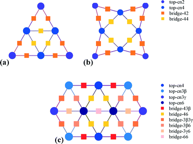 | ||
| Fig. 1 Lattice structures of the three Au nanoclusters, Au6− (a), Au8− (b) and Au10− (c), denoting the sites that were taken into account in the models. | ||
The energetics model contained the binding energies of all intermediates to the pertinent sites (top and bridge) and explicitly accounted for multi-site species, such as carbonate. Moreover, strong repulsive interactions between O2 adsorbates were incorporated into the energetics model, since the DFT calculations showed that a maximum of one oxygen molecule can bind to any of these clusters. All energetics models are presented in detail in the ESI.†
The reaction mechanism for each of the three nanoclusters contained adsorption/desorption, diffusion and surface reactions, and Eley-Rideal reaction elementary steps computed via DFT. Transition state theory approximations were used to calculate the rate constants (see the ESI† of ref. 44). Within the KMC framework, event occurrence is treated as a Poisson stochastic process, and to simulate the occurrence of the elementary events, Zacros utilizes a rejection-free algorithm with local updating of the propensities.45 In view of the stochastic nature of KMC, ensembles of 100 (for Au6−) or 10 clusters (for Au8− and Au10−) were used to investigate the kinetics. All simulations were performed at a temperature of 250 K for an isomolar mixture of CO and O2 at 1 bar. It should be noted that we have successfully applied this methodology to the MgO supported Au6 clusters very recently,46 by investigating the support effects and reaction mechanism with quantum mechanical calculations (RI-BP86 and B3LYP level of approximation, respectively) and importing the DFT-calculated reaction energetics into graph-theoretical kinetic Monte Carlo simulations.
Results
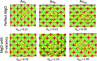
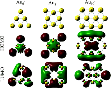
Au clusters up to the Au13 size (consisting of 13 atoms) exhibit planar geometries. When these clusters are supported on MgO with O vacancies, they are negatively charged.29,46 Each O vacancy can give electron density to the clusters approximately close to one electron (−0.8 to −1.4 |e|), whereas, when the clusters are supported on a perfect MgO the charge that is transferred is significantly smaller (−0.2 to −0.3 |e|). This behavior is illustrated in Fig. 2, where we show the interactions of Au6, Au8 and Au10 with MgO and the total charge transferred from the support.This electron density can be transferred to the clusters, even when the clusters are 20 Å away from the support vacancy.47 Clusters with even number of atoms will end up with an odd number of electrons after this electron transfer from the support vacancy, which will favor O2 adsorption. In Fig. 3, we present the HOMO and LUMO (highest occupied and lowest unoccupied molecular) orbitals of the Au6−, Au8− and Au10− clusters (catalysts of interest). CO (O2) is an electron donor (acceptor) molecule and preferentially interacts with sites on the clusters where the LUMO (HOMO) orbitals are localized. The first complexity in these molecular-sized catalysts arises from the fact that the HOMO and LUMO orbitals are not necessarily localized on the lowest coordinated sites of the clusters.32 As a result, the lowest coordinated sites are not necessarily the strongest adsorption sites on the catalysts. This is exemplified in the case of Au10− where the HOMO orbital, which is semi-occupied, is localized primarily on the Au atoms that exhibit coordination number 4 (and to their first neighbors with coordination number 3) and not explicitly to the lowest coordinated sites of the cluster (with coordination number 3). Thus, molecular oxygen adsorbs on the Au10− cluster with a bidentate configuration on top of the Au atoms where the HOMO orbital is localized (see the initial state in Fig. 4(d), vide infra).
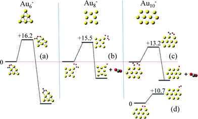
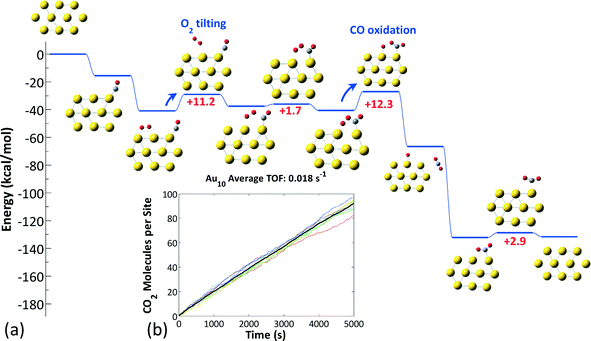
Next we calculated the detailed energetics of the CO oxidation reaction (step 1: CO* + O2* → CO2 + O* and step 2: CO* + O* → CO2) on these three clusters, by taking into consideration every possible adsorption configuration of CO and O2. As a result, we calculated approximately 160 catalytic events which include: adsorption, reaction, and desorption of all the gas species. Details about the calculations and reaction energy pathways appear in the ESI† file. In Fig. 4(a)–(c), we selectively present the first step of the CO oxidation reaction from a 4-center CO–O2 adsorbed intermediate that has been reported to be the rate-limiting step in the CO oxidation reaction.38 These specific reaction steps on each of the three clusters appear to control their reactivity, but for completely different reasons, as we will show next with our kinetic Monte Carlo (KMC) simulations. Just by comparing the density functional theory (DFT) calculated reaction barriers for Au6− = 16.2, Au8− = 14.8, and Au10− = 13.2 (kcal mol−1) presented in Fig. 4(a)–(c), one could conclude that Au10− appears to be the most active cluster among the three and the activity is a monotonic function of size, in contradiction to experiments. In Au6−, the product of the first CO oxidation reaction step is carbonate (CO3) and not CO2. Carbonate binds very strongly on the catalyst and its dissociation to a CO2 molecule is highly unfavorable.46 A unique reaction step in the Au10− case is the O2 “tilting” presented in Fig. 4(d). O2 preferentially interacts with the cluster with the bidentate configuration due to the electronic reasons we discussed in the previous paragraph. In this configuration, O2 has to tilt in order to react with CO through the 4-center intermediate, which requires an activation energy of 10.7 kcal mol−1.
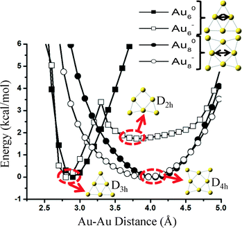
The reason why carbonate forms on Au6− is because the cluster has two almost isoenergetic (ΔE ~ 2 kcal mol−1) geometries of D3h and D2h symmetries and can restructure with a very small transformation barrier of ~4 kcal mol−1. Freezing the cluster in its initial geometry during reaction pathway calculations would result in the formation of CO2 and not carbonate. Interestingly, as we show in Fig. 5, a similar transition from a D4h to a stable geometry of lower symmetry (e.g., D2h) does not exist in Au8− neither on the neutral states of these two clusters (Au60, Au80). Even though it is possible that reconstruction happens on the Au8− catalyst under reaction conditions (e.g., adsorbate-induced, see the detailed reaction mechanism presented in Fig. 7(b)), we show that at least for the specific elongation coordinate (similar to the one causing the reconstruction of Au6) shown in Fig. 5, the cluster is stable (i.e., symmetry-induced reconstruction does not occur).
To investigate the reactivity of the three different nanoclusters for CO oxidation, we performed first-principles KMC simulations44 using our ab initio data as input and the Zacros software implementation of the graph-theoretical KMC method.42,43 By calculating the number of CO2 molecules produced per site per time, we estimated the turnover frequencies (TOFs) for each Au structure, and by analyzing the statistics of occurrence of each elementary step, we identified the dominant pathways for each structure. The results are presented in Fig. 6–8.
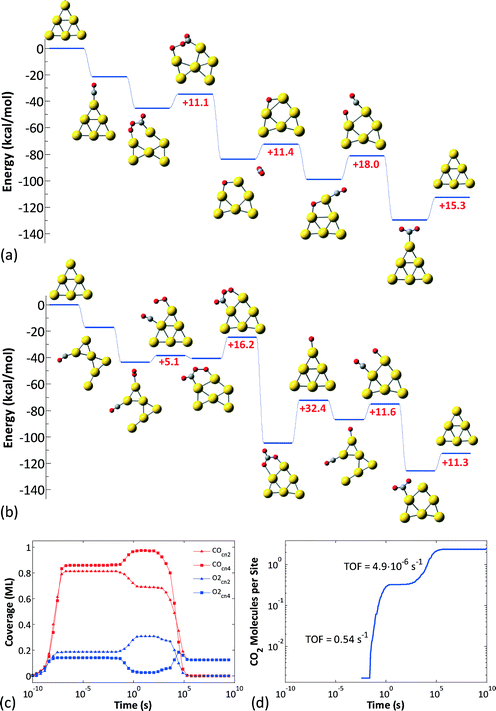 | ||
| Fig. 6 (a) Unhindered CO oxidation pathway on the Au6− nanocluster, with CO initially adsorbed on a CN2 site and O2 on a CN4 site. (b) The pathway resulting in poisoning of the Au6− nanocluster; here, CO initially adsorbs on a CN4 site and O2 on a CN2 site. (c) Average coverages of CO and O2 on the CN2 and CN4 sites of the Au6− nanocluster, calculated from an ensemble of 100 clusters (100 KMC runs with different random seeds). (d) Average number of CO2 molecules produced per cluster in an ensemble of 100 clusters. After exhibiting some transient activity, Au6− is poisoned (see also ref. 46). | ||
For Au6− our previous work identified two possible pathways depending on the initial binding sites of O2 and CO (Fig. 6(a) and (b)),46 both of which are active in different timescales: the contribution of each pathway is revealed in Fig. 6(c), which depicts the CO and O2 coverages on the different site types of the Au6− cluster (all data are averages over an ensemble of 100 KMC runs), and in Fig. 6(d), which shows the CO2 molecules produced per site. Evidently, there are two phases of transient activity, followed by the eventual poisoning of the cluster. Thus, initially, CO and O2 are randomly adsorbed on the CN2 and CN4 sites, resulting in approximately same coverages for both site types. At timescales of around 10−2 s, the CO oxidation reaction initiates and proceeds via the first pathway (Fig. 6(a)), as evidenced by the depletion of CO on CN2 and O2 on CN4. Subsequently, on the timescale of 1 s, the second pathway becomes active (Fig. 6(b)). This delay can be attributed to the slightly higher barriers thereof: 5.1 kcal mol−1 for the 4-center intermediate formation and 16.2 kcal mol−1 for the conversion of the latter to CO3 (in the first pathway the higher barrier is 18 kcal mol−1 for the final O + CO reaction). CO3 formation via the 2nd pathway competes with the 1st pathway; this is why we still see CO2 formation even well after 1 s. Note that the plateau in the log–log diagram for the CO2 produced in Fig. 6(d) is due to the distortion of timescales in the logarithmic scale: short timescales are magnified and long timescales shrink. Plotted in a linear scale, it is apparent that CO2 formation does not cease temporarily to resume with higher rates later; it proceeds continuously, but with a much lower rate after about 1 s. Eventually, the catalyst gets poisoned by CO3: the non-zero average coverages for O2 at CN4 and CO at CN2 are due to the nanoclusters with 2 CO3 molecules in the opposite sides of the triangular Au6 structure.
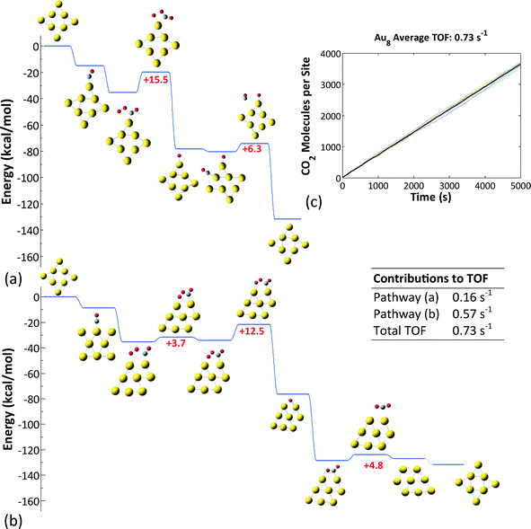
Au8−, on the other hand, was found to exhibit the highest reactivity among the three clusters investigated (Fig. 7). The reaction proceeds via the formation and decomposition of a four-center CO⋯O2 intermediate. Two pathways contribute to the overall activity: the first one involves a monodentate binding configuration of the four-center intermediate, whose decomposition according to step (b) in Fig. 3 is rate limiting. The second pathway implicates a bidentate configuration and entails adsorbate-induced cluster reconstruction. The latter was taken into account implicitly in the energetics of the reaction steps. Notice that this cluster reconstruction is induced by the adsorption of the reacting species and not by the symmetry of the cluster, as we showed in Fig. 5. The average turnover frequency (TOF) of this cluster was estimated to be 0.73 s−1 and was the highest among those of the Au nanoclusters considered.
In the case of Au10−, bidentate O2 species were found to be significantly more stable than monodentate ones (by about 10 kcal mol−1); however, the former are inactive due to the high barriers of the reaction with CO.38 Thus, on the Au10− structure, the chemistry proceeds via the tilting of bidentate O2 to a monodentate (active) configuration (Fig. 8(a)), followed by the reaction between O2 and adsorbed CO, which has an activation energy on the order of 10 kcal mol−1 (the exact values depend on the actual sites occupied and are shown in the ESI† file). The sequence of these two steps is rate-limiting for the CO oxidation reaction on Au10−. The TOF of this cluster is approximately 0.02 s−1 (Fig. 8(b)), which is lower than that of Au8− by more than an order of magnitude and in qualitative agreement with experimental observations (Au6− inert, Au8− active, Au10− less active than Au8−).28–30
As a final note, this work highlights that more sophisticated models need to be developed to correlate the catalytic activity with the electronic properties of the clusters, which in turn arise from their geometric characteristics.48,49 In addition, the stability of the supported clusters plays an important role in their catalytic behavior. Incorporation of ligands into Au clusters could improve their stability by limiting cluster agglomeration, while maintaining CO oxidation activity.1 However, the reaction mechanisms on these clusters are expected to completely change in the presence of ligands.
Conclusions
Using multiscale modeling simulations, we investigated the CO oxidation behavior of sub-nanosized Au catalysts that consist of a few metal atoms. This study unravels a high degree of complexity in the catalytic behavior of Au clusters: competing physicochemical phenomena on the catalyst result in the experimentally observed “magic number” CO oxidation activity. Sub-nanocatalysis, despite being attractive due to the atomic-level precision of the catalysts and its often unprecedented performance, remains an empirical field. Simulations, such as the ones presented here, can significantly advance our understanding and lead to better catalysts and processes.Acknowledgements
G. M. and N. A. would like to acknowledge computational support from the Center for Simulation and Modeling (SAM) and start-up funding from the University of Pittsburgh. M. S. acknowledges the use of the UCL Legion High Performance Computing Facility (Legion@UCL), and associated support services, in the completion of the KMC simulations of this work. The material on CO oxidation on Au is also based upon work financially supported by a Marie Curie International Outgoing Fellowship within the 7th European Community Framework Programme. The work conducted at Delaware was supported by grant no. DE-SC0010549 from the (U.S.) Department of Energy (DOE).References
- O. Lopez-Acevedo, K. A. Kacprzak, J. Akola and H. Hakkinen, Nat. Chem., 2010, 2, 329–334 CrossRef CAS.
- Q. Fu, H. Saltsburg and M. Flytzani-Stephanopoulos, Science, 2003, 301, 935–938 CrossRef CAS.
- M. Valden, X. Lai and D. W. Goodman, Science, 1998, 281, 1647–1650 CrossRef CAS.
- B. Hammer and J. K. Norskov, Nature, 1995, 376, 238–240 CrossRef CAS.
- J. Quilter, Science, 1998, 282, 1058–1059 CrossRef CAS.
- G. C. Bond and D. T. Thompson, Catal. Rev.: Sci. Eng., 1999, 41, 319–388 CAS.
- G. Mpourmpakis, S. Caratzoulas and D. G. Vlachos, Nano Lett., 2010, 10, 3408–3413 CrossRef CAS.
- P. D. Jadzinsky, G. Calero, C. J. Ackerson, D. A. Bushnell and R. D. Kornberg, Science, 2007, 318, 430–433 CrossRef CAS.
- Y. G. Sun and Y. N. Xia, Science, 2002, 298, 2176–2179 CrossRef CAS.
- E. Boisselier and D. Astruc, Chem. Soc. Rev., 2009, 38, 1759–1782 RSC.
- M. Haruta, T. Kobayashi, H. Sano and N. Yamada, Chem. Lett., 1987, 16, 405–408 CrossRef.
- T. S. Kim, J. D. Stiehl, C. T. Reeves, R. J. Meyer and C. B. Mullins, J. Am. Chem. Soc., 2003, 125, 2018–2019 CrossRef CAS.
- W. S. Epling, G. B. Hoflund, J. F. Weaver, S. Tsubota and M. Haruta, J. Phys. Chem., 1996, 100, 9929–9934 CrossRef CAS.
- S. D. Lin, M. Bollinger and M. A. Vannice, Catal. Lett., 1993, 17, 245–262 CrossRef CAS.
- B. Schumacher, V. Plzak, M. Kinne and R. J. Behm, Catal. Lett., 2003, 89, 109–114 CrossRef CAS.
- J. D. Stiehl, T. S. Kim, S. M. McClure and C. B. Mullins, J. Am. Chem. Soc., 2004, 126, 13574–13575 CrossRef CAS.
- S. Tsubota, D. A. H. Cunningham, Y. Bando and M. Haruta, in Preparation of Catalysts Vi, 1995, vol. 91, pp. 227–235 Search PubMed.
- M. Haruta, Cattech, 2002, 6, 102–115 CrossRef CAS.
- R. Meyer, C. Lemire, S. K. Shaikhutdinov and H. Freund, Gold Bull., 2004, 37, 72–124 CrossRef CAS.
- D. R. Rainer and D. W. Goodman, J. Mol. Catal. A: Chem., 1998, 131, 259–283 CrossRef CAS.
- M. C. Kung, R. J. Davis and H. H. Kung, J. Phys. Chem. C, 2007, 111, 11767–11775 CAS.
- G. C. Bond, C. Louis and D. T. Thompson, Catalysis by Gold, Imperial College Press, 2006 Search PubMed.
- B. Hvolbaek, T. V. W. Janssens, B. S. Clausen, H. Falsig, C. H. Christensen and J. K. Norskov, Nano Today, 2007, 2, 14–18 CrossRef.
- G. Mpourmpakis, A. N. Andriotis and D. G. Vlachos, Nano Lett., 2010, 10, 1041–1045 CrossRef CAS.
- I. N. Remediakis, N. Lopez and J. K. Norskov, Appl. Catal., A, 2005, 291, 13–20 CrossRef CAS.
- I. X. Green, W. Tang, M. Neurock and J. T. Yates Jr., Science, 2011, 333, 736–739 CrossRef CAS.
- T. Fujitani and I. Nakamura, Angew. Chem., Int. Ed., 2011, 50, 10144–10147 CrossRef CAS.
- A. Sanchez, S. Abbet, U. Heiz, W. D. Schneider, H. Hakkinen, R. N. Barnett and U. Landman, J. Phys. Chem. A, 1999, 103, 9573–9578 CrossRef CAS.
- B. Yoon, H. Hakkinen, U. Landman, A. S. Worz, J.-M. Antonietti, S. Abbet, K. Judai and U. Heiz, Science, 2005, 307, 403–407 CrossRef CAS.
- M. Arenz, U. Landman and U. Heiz, ChemPhysChem, 2006, 7, 1871–1879 CrossRef CAS.
- G. Mills, M. S. Gordon and H. Metiu, Chem. Phys. Lett., 2002, 359, 493–499 CrossRef CAS.
- S. Chretien, S. K. Buratto and H. Metiu, Curr. Opin. Solid State Mater. Sci., 2007, 11, 62–75 CrossRef CAS.
- R. Pal, L. M. Wang, Y. Pei, L. S. Wang and X. C. Zeng, J. Am. Chem. Soc., 2012, 134, 9438–9445 CrossRef CAS.
- G. Li and R. C. Jin, Acc. Chem. Res., 2013, 46, 1749–1758 CrossRef CAS.
- X. Guo, G. Fang, G. Li, H. Ma, H. Fan, L. Yu, C. Ma, X. Wu, D. Deng, M. Wei, D. Tan, R. Si, S. Zhang, J. Li, L. Sun, Z. Tang, X. Pan and X. Bao, Science, 2014, 344, 616–619 CrossRef CAS.
- R. Ahlrichs, M. Bar, M. Haser, H. Horn and C. Kolmel, Chem. Phys. Lett., 1989, 162, 165–169 CrossRef CAS.
- M. J. T. Frisch, G. W. Trucks, H. B. Schlegel, G. E. Scuseria, M. A. Robb, J. R. Cheeseman, G. Scalmani, V. Barone, B. Mennucci, G. A. Petersson, H. Nakatsuji, M. Caricato, X. Li, H. P. Hratchian, A. F. Izmaylov, J. Bloino, G. Zheng, J. L. Sonnenberg, M. Hada, M. Ehara, K. Toyota, R. Fukuda, J. Hasegawa, M. Ishida, T. Nakajima, Y. Honda, O. Kitao, H. Nakai, T. Vreven, J. A. Montgomery Jr., J. E. Peralta, F. Ogliaro, M. Bearpark, J. J. Heyd, E. Brothers, K. N. Kudin, V. N. Staroverov, R. Kobayashi, J. Normand, K. Raghavachari, A. Rendell, J. C. Burant, S. S. Iyengar, J. Tomasi, M. Cossi, N. Rega, J. M. Millam, M. Klene, J. E. Knox, J. B. Cross, V. Bakken, C. Adamo, J. Jaramillo, R. Gomperts, R. E. Stratmann, O. Yazyev, A. J. Austin, R. Cammi, C. Pomelli, J. W. Ochterski, R. L. Martin, K. Morokuma, V. G. Zakrzewski, G. A. Voth, P. Salvador, J. J. Dannenberg, S. Dapprich, A. D. Daniels, Ö. Farkas, J. B. Foresman, J. V. Ortiz, J. Cioslowski and D. J. Fox, Gaussian, Inc., Wallingford CT, 2009.
- N. Nikbin, G. Mpourmpakis and D. G. Vlachos, J. Phys. Chem. C, 2011, 115, 20192–20200 CAS.
- A. Prestianni, A. Martorana, F. Labat, I. Ciofini and C. Adamo, J. Phys. Chem. B, 2006, 110, 12240–12248 CrossRef.
- T. Davran-Candan, A. E. Aksoylu and R. Yildirim, J. Mol. Catal. A: Chem., 2009, 306, 118–122 Search PubMed.
- M. Stamatakis, Zacros: Advanced Lattice-KMC simulation Made Easy, http://tinyurl.com/zacroskmc.
- M. Stamatakis and D. G. Vlachos, J. Chem. Phys., 2011, 134, 214115 CrossRef.
- J. Nielsen, M. d'Avezac, J. Hetherington and M. Stamatakis, J. Chem. Phys., 2013, 139, 224706 CrossRef.
- M. Stamatakis and D. G. Vlachos, ACS Catal., 2012, 2, 2648–2663 CrossRef CAS.
- A. Chatterjee and D. G. Vlachos, J. Comput.-Aided Mater. Des., 2007, 14, 253–308 CrossRef.
- M. Stamatakis, M. A. Christiansen, D. G. Vlachos and G. Mpourmpakis, Nano Lett., 2012, 12, 3621–3626 CrossRef CAS.
- K. McKenna, T. Trevethan and A. Shluger, Phys. Rev. B: Condens. Matter Mater. Phys., 2010, 82, 085427 CrossRef.
- H. Li, L. E. Li and Y. D. Li, Nanotechnology Reviews, 2013, 2, 515–528 CAS.
- J. Liu, K. S. Krishna, Y. B. Losovyj, S. Chattopadhyay, N. Lozova, J. T. Miller, J. J. Spivey and C. Kumar, Chem. – Eur. J., 2013, 19, 10201–10208 CrossRef CAS.
Footnotes |
| † Electronic supplementary information (ESI) available. See DOI: 10.1039/c4cy01295j |
| ‡ Author contributions: N. N., N. A., M. S. and G. M. performed the calculations. G. M., M. S. and D. G. V. conceptualized the study and carried out the advising. G. M. and M. S. wrote the manuscript and all authors edited and proofread the paper. |
| This journal is © The Royal Society of Chemistry 2015 |

