Co@NH2-MIL-125(Ti): cobaloxime-derived metal–organic framework-based composite for light-driven H2 production†
M. A.
Nasalevich‡
a,
R.
Becker‡
b,
E. V.
Ramos-Fernandez
c,
S.
Castellanos
a,
S. L.
Veber
d,
M. V.
Fedin
d,
F.
Kapteijn
a,
J. N. H.
Reek
*b,
J. I.
van der Vlugt
*b and
J.
Gascon
*a
aCatalysis Engineering, Applied Sciences, Delft University of Technology, Julianalaan 136, 2628 BL, Delft, The Netherlands. E-mail: j.gascon@tudelft.nl
bHomogeneous, Bioinspired and Supramolecular Catalysis, van't Hoff Institute for Molecular Sciences, University of Amsterdam, Science Park 904, 1098 XH, Amsterdam, The Netherlands. E-mail: j.i.vandervlugt@uva.nl; j.n.h.reek@uva.nl
cLaboratorio de Materiales Avanzados, Departamento de Química Inorgánica-Instituto Universitario de Materiales, Universidad de Alicante, Ap. 99, E-03080 Alicante, Spain
dLaboratory of Magnetic Resonance, International Tomography Center, Institutskaya 3A, Novosibirsk 630090, Russia
First published on 18th November 2014
Abstract
We present a synthetic strategy for the efficient encapsulation of a derivative of a well-defined cobaloxime proton reduction catalyst within a photoresponsive metal–organic framework (NH2-MIL-125(Ti)). The resulting hybrid system Co@MOF is demonstrated to be a robust heterogeneous composite material. Furthermore, Co@MOF is an efficient and fully recyclable noble metal-free catalyst system for light-driven hydrogen evolution from water under visible light illumination.
Broader contextThe development of new strategies for the efficient valorization of solar light is one the most important challenges we face nowadays. Among the different possibilities, dihidrogen molecule is considered as one of the possible future energy carriers allowing for CO2-free energy cycle. Although the photocatalytic water splitting was the first photocatalytic reaction to be discovered, no photocatalytic systems for this reaction have been industrially applied. This is both due to the fact that most discovered catalysts rely on the use of noble metals and to the low activities achieved so far by alternative catalysts. The application in this field of materials such as metal–organic frameworks (MOFs) can be a game changer in this research field. MOFs have been proven to be photoactive and their optical properties can be easily tuned towards visible light operation. The current challenge lies in the development of more appropriate active sites for the desired photocatalytic cycle. In this manuscript, we report a new strategy to achieve this goal. By introducing a derivative of the well-known molecular Co-based electrocatalyst Co-dioxime-diimine into the pores of a photo-active NH2-MIL-125(Ti) following a ‘Ship-in-a-bottle’ strategy, we were able to synthesize a highly active photocatalyst composite free of noble metals, and fully recyclable. Because of the novelty and the implications of this work, we feel that it might appeal to the interdisciplinary readership of energy and environmental science. The journal has previously been an important forum for the research topics touched upon in this paper (new earth abundant materials and their application in (photo) catalysis and hydrogen evolution from water under visible light illumination). We would be glad to contribute to this discussion with one of the first examples of synergetic action between a MOF and a molecular catalyst for application in photocatalysis. |
1. Introduction
The direct conversion of solar energy into chemical fuel is among the most important grand challenges today.1 In analogy to natural photosynthesis, the best strategy to store solar energy is in chemical bonds of energy-dense molecules such as dihydrogen.2 A technologically sound and scalable solar-driven H2 production system from water requires not only robust functionalities for light-harvesting, charge transport, and catalysis and their efficient and durable interplay but also necessitates the use of earth-abundant elements and the assembly into practical devices.3,4Recent advances in photocatalytic water splitting using earth-abundant composites – consisting of inorganic semiconductors and (organometallic) co-catalysts – have demonstrated the viability of designing complex assemblies. Moreover the overall reaction rate in such systems can often be influenced by tuning the individual constituents of the composite material.5 Following this approach, the photocatalytic activity of TiO2, firstly reported by Fujishima and Honda, has been greatly increased ever since.6 Doping of the oxide with light elements such as nitrogen7 as well as with metals8 are among the most useful strategies. Dominant crystal facets and the lifetime of photogenerated charge carriers were recognized as key factors influencing the rates of photocatalytic reactions.9,10 Another example of assembling a complex composite for H2 production was recently reported by Qiao and co-workers. The system, consisting of earth-abundant elements (Zn, Cd, Ni), afforded a quantum efficiency of around 30%.11 Despite the impressive achievements in the field, photocatalysis with semiconductors remains challenging. Limited tuneability and the fact that photogenerated charges need to travel to the surface through the bulk semiconductors have to a large extent hindered further progress.
Metal–organic frameworks (MOFs) are ideal materials for the modular design of complex assemblies.5,12,13 Distinct from traditional inorganic materials, MOFs can be reliably synthesized as extended hierarchical structures from well-defined molecular building blocks via crystal engineering.14,15 MOFs have found application in organic photocatalysis, with the metal-containing nodes acting as semiconductor clusters spaced by photo-active organic struts.12,16–21 Efficient photo-initiated strut-to-node electron-transfer has been demonstrated, although the reported photocatalytic activity cannot compete with traditional semiconductors.22 Their performance can be enhanced by introduction of additional catalytic species, but these are commonly based on precious metals and the MOF typically only acts as container.23–26
To date, examples of cooperative action between a MOF matrix and encapsulated (molecular) catalysts are very scarce.24,25,27–29 Inspired by natural photosynthesis, we envisioned a multi-component system that would allow for efficient photon-capture, charge-separation, electron-transport and catalytic turnover at different locations of a guest@MOF composite. This would offer efficient charge transfer between a stable, photo-active MOF structure and the encapsulated proton reduction catalyst under visible-light illumination. To achieve this overall modular design, the composite should contain (i) photoresponsive struts for fast light-harvesting, (ii) redox-active (multi) metallic nodes to allow charge-separation and accumulation of electrons and (iii) an appropriate MOF topology (i.e. large cavities connected by smaller windows) to encapsulate a molecular complex/nanocluster for productive turnover.
We herein demonstrate this principle with a cobaloxime-derived MOF-based (Co@MOF) system, consisting solely of earth-abundant elements. This material shows outstanding performance for several cycles without loss of activity in the light-driven hydrogen evolution from water under visible light illumination.
The synthetic protocol for assembling Co@MOF is described, followed by extensive characterization of the as-synthesized composite and the catalyst at work. However, a full comprehensive determination of the structure of this composite remains challenging. Commonly, the chemistry behind molecular cobalt complexes in solution and the ones embedded in rigid matrixes such as zeolites30 is substantially different. Moreover, the lability of ligands constituting co-baloximes might cause coordination to the surrounding matrix resulting in cobalt species with different electronic properties.31 Notwithstanding the aspects still to be unraveled, the remarkable performance of the MOF-based composite demonstrates the large application potential of the modular multifunctional design here presented.
2. Experimental
2.1. Materials and reagents
All chemicals were purchased from Sigma-Aldrich and Acros Organics and were used without further purification. Ligand LH2 (ref. 32) and cobaloxime (1)33 were prepared according to modified literature procedures. Elemental analysis was performed by Kolbe Mikroanalytisches Laboratorium, Mülheim, Germany.2.2. Syntheses
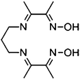
The crude ligand, N2,N2′-propanediylbis(2,3-butanedione 2-imine 3-oxime), was prepared using the method reported by Uhlig and Friedrich.32 The resulting ligand was purified by repeated crystallizations from hot ethanol and washing with diethyl ether. This yields the pure ligand as a white solid, albeit in low yield (<10%). 1H-NMR (400 MHz, DMSO-d6) δ 11.42 (s, 2H, N–OH), 3.46 (t, J = 6.7 Hz, 4H, CH2), 1.98 (s, 6H, CH3), 1.93 (qn, J = 6.7 Hz, 2H, CH2), 1.91 (s, 6H, CH3). Note that the quintet at 1.93 ppm is partially masked by the singlet at 1.91 ppm. MS-CSI for C11H20N4O2 ((DOH)2pn): m/z calculated 241.16645, observed 241.16521 (M+). Elemental analysis: found: C, 54.79; H, 8.35; N, 23.23. C11H20N4O2 requires C, 54.98; H, 8.39; N, 23.32%.
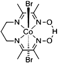
The crude complex was prepared using the method reported by Costa et al.33 The resulting cobaloxime was purified by repeated crystallizations from ethyl acetate, yielding a green microcrystalline solid in 17% yield. 1H-NMR (400 MHz, CDCl3) δ 19.34 (s, 1H, OHO), 4.12 (t, 4H, CH2), 2.65 (qn, 2H, CH2), 2.61 (s, 6H, CH3), 2.61 (s, 6H, CH3). Note that the quintet at 2.65 and both singlets at 2.61 partially overlap. In the case of very impure product, the complex can be purified on Bio-Beads S-X8 (Bio-Rad) using THF as eluent. MS-CSI for C13H22BrCoN5O2 (CoBr(MeCN) (DO) (DOH)pn): m/z calculated 418.0289, observed 418.0284 (M+). Elemental analysis: found: C, 29.17; H, 4.20; N, 12.07. C11H19Br2CoN4O2 requires C, 28.84; H, 4.18; N, 12.23.
All the ratios listed above are given for the highest catalyst loading of 2.7 wt% of Co (as determined by ICP analysis).
2.3. Characterization and methods
For all samples, many digital images were recorded, and all useful images have been transferred via ftp.
Using a pure D2 sample, it was confirmed that D2 only gives rise to ion current for m/z = 4 and does not fragment to m/z = 2.
2.4. Photocatalysis
In a typical experiment, Co@MOF (5.0 ± 0.2 mg) was suspended in a mixture of acetonitrile (5 mL), triethylamine (1 mL) and deionized water (100 μL) and the suspension degassed by bubbling nitrogen for 10 min while stirring. The resulting suspension was transferred (under nitrogen atmosphere) to a photo-reactor (head space approximately 200 mL) which was purged with nitrogen beforehand. The sample was irradiated continuously with a 500 W Hg/Xe lamp (Hamamatsu Photonics L8288) at the lamp's focal point (ca. 45 cm) using an IR filter (circulating water; ca. 25 cm path length) and a 408 nm UV cut-off filter. The head space was sampled continuously (every 10 min; 20 μL sample volume) by online gas chromatography (Interscience CompactGC; molecular sieve column, Ar carrier, TCD detector) using internal calibration against the dinitrogen peak.2.5. Recycling
After irradiation, the reaction mixture was transferred to a centrifuge tube and diluted with acetone (5 mL). The suspension was centrifuged at 4000 rpm for 20 min and the supernatant (including some fine catalyst particles) was discarded. The solid residue was subjected to a gentle acetone wash (10 mL) and again centrifuged (twice). The final solids were air dried, and used in the next photocatalytic run ‘as is’. Note that during recycling, traces of material are most probably lost as fine particles in the mother liquor. Quantification of the recovered material was not possible due to the small sample mass and presence of solvent traces, but the yield seemed to be quantitative.3. Results
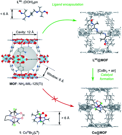
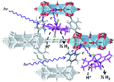
In this work we aimed at encapsulating the well-defined molecular electrocatalyst (1) within the cavities of a photoactive MOF, namely NH2-MIL-125(Ti). For this purpose we designed a two-stage ‘ship-in-the-bottle’ strategy (Scheme 1). Firstly, the pores of the MOF structure are loaded with the flexible organic component (DOH)2pn (LH2), where after addition of CoBr2 under aerobic conditions should lead to assembly of complex 1 within the large cavities of the metal–organic framework. The size-selectivity principle is key to this intra-MOF complex synthesis, as the dimensions of the intact CoIII pre-catalyst exclude diffusion into or out of the MOF windows as confirmed by control experiments summarized in Fig. S6.†34The resulting catalysts were extensively characterized and their performance in visible light-driven hydrogen evolution was evaluated. In this section the experimental results are reported, followed by the discussion in the next section. We emphasize the discrimination between the two since the numerous characterization techniques employed in this study suggest the formation of the designed photocatalytic composite Co@MOF but do not comprehensively prove the exact configuration of the molecular species of cobalt within the pores of the MOF.
3.1. Catalysts characterization
ICP analysis confirms the inclusion of Co-containing species into the MOF with the total cobalt content in a range of 1.1–2.7 wt%.
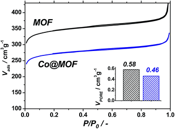 | ||
| Fig. 1 Nitrogen isotherms recorded at 77 K for pristine NH2-MIL-125(Ti) (black) and Co@MOF (blue). Total pore volumes calculated at 0.9 P/P0 (bottom right). | ||
The pristine NH2-MIL-125(Ti) displays a total pore volume of 0.58 cm3 g−1, in line with previous reports,35 while the Co@MOF shows a significantly lower N2-uptake, resulting in a total pore volume of 0.46 cm3 g−1. At the same time, the solid remains microporous and preserves a significant fraction of the pore volume. This indicates that the cobalt species formed by the synthetic two-stage procedure do not block the pores of the framework and are likely to be of molecular size due to the size restrictions by the cavities of the MOF.
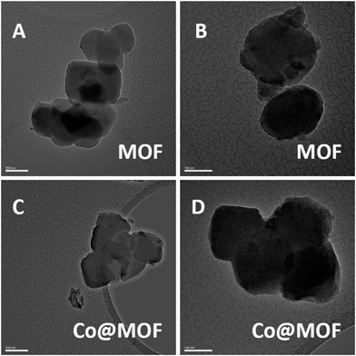 | ||
| Fig. 2 TEM of pristine NH2-MIL-125(Ti) (200 nm – A; 100 nm – B) and Co@MOF (200 nm – C; 100 nm – D). | ||
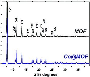
The pristine MOF consists of well-defined crystallites with a diameter of approximately 400 nm. The Co@MOF crystallites are nearly identical to the ones of the MOF with no agglomerates nor core/shell type structure found by TEM. In fact, the cobalt entities within the MOF crystallites could not be distinguished by this technique implying that the size of the cobalt species is not exceeding 2 nm. EDX analysis performed on multiple regions in Fig. 2D shows nearly the same cobalt content on the surface of the crystallite and in the bulk [Table S1†]. Moreover, SEM EDX mapping on μm scale demonstrated the absence of large agglomerates of Co or Ti and confirmed the homogeneity of the composite (Fig. S12†). These observations support the hypothesis that the cobalt species is molecularly dispersed within the MOF cavities, in line with the nitrogen physisorption results.
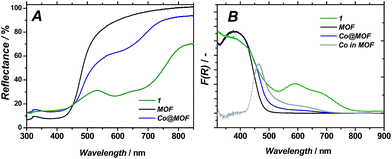 | ||
| Fig. 5 Diffuse reflectance UV/Vis spectra of 1, pristine MOF and Co@MOF (A); Kubelka–Munk representation (B); ‘Co in MOF’ curve is obtained by subtracting MOF from Co@MOF. | ||
UV/Vis spectroscopy on Co@MOF catalyst showed the appearance of two new features at 440 and 585 nm (see Fig. 5B) as compared to the pristine framework, which are ascribed to the inclusion of complex 1 (maxima at 400 and 600 nm).36 The major optical absorption of 1 is found at around 400 nm. However, this absorption band of 1 is masked in Co@MOF by the n–π* transition of NH2-MIL-125(Ti) that corresponds to a HOMO-LUMO gap energy of 2.73 eV. It should be emphasized that the intense longer wavelength transitions36 characteristic for Co2+ species were not observed in Co@MOF. The spectrum is attributed to be the result of a combination of individual absorption spectra from NH2-MIL-125(Ti) and 1. Thus the newly appeared intense band allows for the estimation of the HOMO-LUMO gap of the 1-derived entities encapsulated in the MOF (2.59 eV, Fig. S8†), while the gap of the NH2-MIL-125 is assumed to be equal to the pristine MOF.
As can be seen in Fig. 6B, the pristine NH2-MIL-125(Ti) displays one single emission band centred at 433 nm, in line with the previously reported data.37 In case of pristine 1, photoemission does not occur upon excitation at 590 nm, in spite of the absorption band at this wavelength shown in Fig. 5B, corresponding to weak oscillator strength optical transitions of the cobaloxime. In contrast, excitation at 380 nm yields an intense well-defined emission band centred at 435 nm matching the emission of the as-prepared MOF. Co@MOF demonstrates emissions markedly different from the ones found for NH2-MIL-125(Ti). The broad emission band has now two distinct components centred at 418 and 437 nm. We speculate that the following assignments are possible: (i) blue-shifted emission of 1 confined in the MOF environment at 418 nm and unperturbed emission of NH2-MIL-125(Ti) at 437 nm; (ii) blue-shifted emission of the MOF interacting with 1 and unperturbed emission of 1; (iii) two different emitting entities within the MOF: one interacting with 1 and the other unperturbed. Fluorescence lifetimes of the excited states for NH2-MIL-125(Ti) and Co@MOF were also investigated. Characteristic decay time was found to be 11.3 ns in the case of the MOF while it was 11.6 ns for Co@MOF system. The same experiments carried out in deoxygenated CH3CN suspension showed elongation of both lifetimes that became 16.5 ns (Fig. S9†).
![[thin space (1/6-em)]](https://www.rsc.org/images/entities/char_2009.gif) :
:![[thin space (1/6-em)]](https://www.rsc.org/images/entities/char_2009.gif) doublet
doublet![[thin space (1/6-em)]](https://www.rsc.org/images/entities/char_2009.gif) :
:![[thin space (1/6-em)]](https://www.rsc.org/images/entities/char_2009.gif) singlet (1
singlet (1![[thin space (1/6-em)]](https://www.rsc.org/images/entities/char_2009.gif) :
:![[thin space (1/6-em)]](https://www.rsc.org/images/entities/char_2009.gif) 1
1![[thin space (1/6-em)]](https://www.rsc.org/images/entities/char_2009.gif) :
:![[thin space (1/6-em)]](https://www.rsc.org/images/entities/char_2009.gif) 1) multiplicity at 8.34, 8.24 and 8.21 ppm, respectively, arising from the amino-terephthalate aromatic linker (Fig. S3†). Most remarkably, and contrary to the case of the pure MOF, additional signals in the aliphatic region were also detected. A comparable overlapping of signals in the same window range was observed after performing the same digestion procedure on the cobaloxime complex (Fig. S4†). Thus, although an unequivocal assignment cannot be ventured, this result is in agreement with the presence of extra organic residues originating from the cobaloxime moiety in the Co@MOF sample.
1) multiplicity at 8.34, 8.24 and 8.21 ppm, respectively, arising from the amino-terephthalate aromatic linker (Fig. S3†). Most remarkably, and contrary to the case of the pure MOF, additional signals in the aliphatic region were also detected. A comparable overlapping of signals in the same window range was observed after performing the same digestion procedure on the cobaloxime complex (Fig. S4†). Thus, although an unequivocal assignment cannot be ventured, this result is in agreement with the presence of extra organic residues originating from the cobaloxime moiety in the Co@MOF sample.
3.2. Photocatalytic performance
In order to assess the ability of Co@MOF to perform light-driven hydrogen evolution, the catalyst was suspended in a mixture of acetonitrile, triethylamine and water (5![[thin space (1/6-em)]](https://www.rsc.org/images/entities/char_2009.gif) :
:![[thin space (1/6-em)]](https://www.rsc.org/images/entities/char_2009.gif) 1
1![[thin space (1/6-em)]](https://www.rsc.org/images/entities/char_2009.gif) :
:![[thin space (1/6-em)]](https://www.rsc.org/images/entities/char_2009.gif) 0.1 v/v), deoxygenated and exposed to visible-light illumination. Online-GC monitoring of the composition of the head space of the reactor enabled assessment of the catalytic performance of pristine MOF and Co@MOF catalyst (Fig. 7A). Results obtained for catalysts bearing different Co loadings are depicted in Fig. 7B.
0.1 v/v), deoxygenated and exposed to visible-light illumination. Online-GC monitoring of the composition of the head space of the reactor enabled assessment of the catalytic performance of pristine MOF and Co@MOF catalyst (Fig. 7A). Results obtained for catalysts bearing different Co loadings are depicted in Fig. 7B.
When cobaloxime alone is used as homogeneous catalyst, no hydrogen evolution is observed. Indeed, catalyst 1 is known to be an excellent electrocatalyst, but cannot act as photocatalyst in the absence of a separate photo-sensitizer.38 In agreement with previous reports, pristine NH2-MIL-125(Ti) was confirmed to produce only a moderate amount of hydrogen gas.24 The novel assembly system Co@MOF showed markedly improved photocatalytic performance, with up to 20-fold higher H2 production rate compared to pristine cobalt-free MOF. More importantly, Co@MOF maintains a constant TOF of 0.8 h−1 even after 65 hours of total operation, indicating a high stability under illumination conditions. Moreover, similar TOFs (per Co atom) are obtained for catalysts bearing different amounts of cobalt entities, even for catalysts containing up to one cobalt atom per MOF cavity, demonstrating the absence of diffusion limitations and efficient charge transfer even at relatively high loadings. Additional kinetic experiments demonstrate that, once the stepwise assembly of Co@MOF is completed, no leaching of Co occurs from the composite (Fig. 7C); the system could be recycled several times without any loss of activity and with no remaining catalytic activity in solution after filtration of the catalyst. The external quantum efficiency (EQE) of the best performing Co@MOF catalyst (2.7 w% Co) was found to be ca. 0.5% (ESI†). The calculated apparent activation energy for hydrogen production using Co@MOF was 0.4 eV (ESI†).
3.3. Proton source for hydrogen evolution
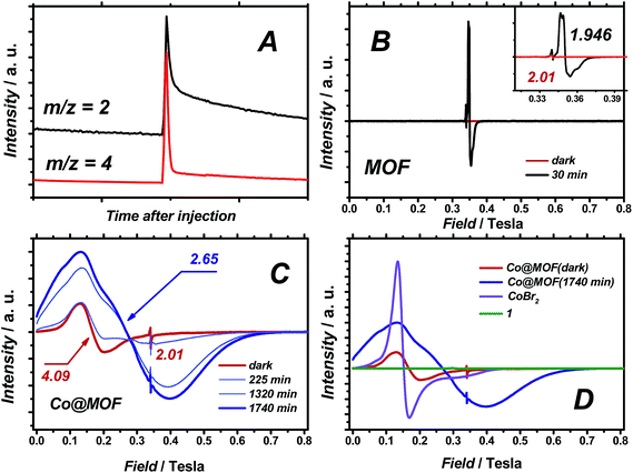
When D2O was employed as a reactant, significant amounts of D2 were observed (H2/D2 ≈ 1), evidencing the participation of water in the formation of hydrogen gas (Fig. 8A). In the present system, the formed triethylamine radical cation has a pKa comparable to water,39 and additional formation of H2 through proton exchange between the two species seems reasonable.3.4. Mechanistic aspects of hydrogen evolution catalysed by Co@MOF assessed by EPR
Quasi in situ EPR experiments on Co@MOF and pristine NH2-MIL-125(Ti) at 40 K after illuminating at room temperature in the presence of an electron-donor indicate efficient charge transfer from the MOF to the cobalt species within the composite.40 Continuous wave (CW) EPR spectra of NH2-MIL-125(Ti) and Co@MOF were recorded at X-band microwave frequency (9.55 GHz). Fig. 8B displays CW EPR spectra of pristine NH2-MIL-125(Ti) in the dark and after 30 min of visible light illumination.An intense EPR signal centred at g = 1.94 evolved upon irradiation, which was attributed to paramagnetic TiIII formed by ligand-to-metal charge transfer (LMCT).24,25 The small downfield feature at g = 2.01 is associated with the spatially confined amino-groups in the MOF.26,41 The EPR spectrum of Co@MOF in the dark (Fig. 8C), with a broad signal around g ≈ 4, is similar to that of high-spin CoBr2 in CH3CN, indicating the presence of residual high-spin CoII impurities (Fig. 8D). The major fraction of cobalt is believed to be in the stable low-spin diamagnetic CoIII state. Exposing Co@MOF to visible light for 22 hours results in the gradual rise of a new broad and intense line, significantly upfield-shifted with respect to CoBr2 admixtures. Quantitative analysis of the EPR data shows a ten-fold higher integral intensity for this paramagnetic signal after illumination compared to the ‘dark’ sample. This photoinduced EPR signal, simulated using reasonable effective g-tensor gx = 6.0, gy = 2.4, gz = 1.7, can be assigned to the high-spin CoII species (ESI†).42 Importantly, contrary to the pristine MOF sample, no EPR signal was detected for a TiIII species in Co@MOF, demonstrating the efficient charge transfer between the photogenerated charge-separated state in the MOF and 1-derived species.
4. Discussion
The two-stage ‘ship-in-a-bottle’ synthetic protocol followed in this study resulted in the synthesis of a Co@MOF photocatalytic composite: a catalyst free of noble metals, recyclable and displaying a stable TOF of 0.8 h−1 even after 65 hours of operation. The introduction of the cobaloxime-derived active sites into the cavities of the framework resulted in a 20-fold enhanced photocatalytic activity compared to the pristine NH2-MIL-125(Ti) used as a benchmark. Importantly, the catalyst utilizes water as a source of protons. With all these characteristics, the present composite outperforms every MOF-based analogue reported so far in literature (ESI†). Having said this, the actual structure of the Co species in the composite and the exact mechanism behind its remarkable performance are still unclear. In the following section these aspects are discussed in detail.4.1. Modular design
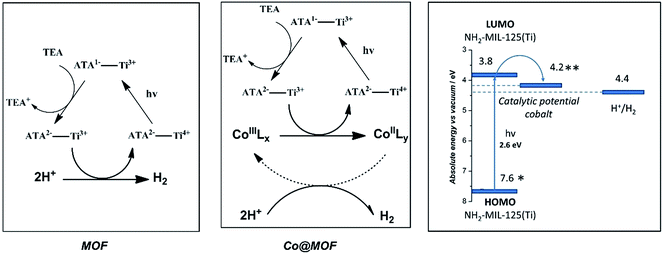
NH2-MIL-125(Ti) was selected as host material because (i) the overall MOF structure is stable in aqueous media,43,44 (ii) the multinuclear Ti-centers are both photo- and redox-active24,45 and (iii) recent experimental37 and theoretical studies46 have shown that the photochemical properties can be tuned by changing the aromatic linker. It is noteworthy that NH2-MIL-125(Ti) has been used for photocatalytic hydrogen production, both in the absence and presence of Pt-nanoparticles,24 suggesting that the reduction potential of the excited states in the MOF is sufficient to drive proton reduction in line with computational predictions.47 We chose the oxygen-tolerant and readily synthesized cobalt complex 1 CoIIIBr2(LH) (LH = (DO) (DOH)pn), previously employed as electrocatalyst for proton reduction,48,49 as molecular guest to demonstrate our concept50,51 illustrated in Scheme 2:4.2. Role of cobalt active sites
First of all, the importance of cobalt as an additional catalytic site should be underlined. From the catalytic experiments displayed in Fig. 7B it is evident that the rate of the photo-assisted transformation increases with higher cobalt loading. Importantly, the injection of a deoxygenated solution of CoBr2 into the working catalyst suspension immediately suppressed the activity of the composite as shown in Fig. S16.† The composite was subjected to 70 hours of reaction to ensure the stable operation before the CoBr2 was injected. Similar observations were reported by Marassi and co-workers, who found that the first step in electrocatalytic hydrogen formation catalysed by 1 is the displacement of the axial bromido ligands.52 This dissociative process is at equilibrium and can be shifted towards the six-fold coordinated complex upon the addition of Br-ions. Moreover, our experiments with CoBr2 injection emphasize the importance of using the ligand LH2 [(DOH)2pn] as a precursor for the assembly of the catalytically active composite. In order to further confirm the key role of the LH2 ligand, we prepared an additional composite by exposing the pristine MOF to the same synthetic conditions as for the Co@MOF assembly except that no ligand was added to the suspension or previously encapsulated in the MOF system. The resulting composite was subjected to UV/Vis spectroscopy and photocatalytic tests. The resulting material entitled CoBr2@MOF produced no hydrogen after 24 hours of irradiation. Moreover, the absorption spectrum of the material is substantially different from the one of Co@MOF, as illustrated in Fig. S7.† These control experiments prove the necessity of employing the organic ligand for the assembly of a photocatalytically active Co@MOF composite. We should mention that inhibition of the photocatalytic reactions by introducing Br was observed for both the MOF and Co@MOF. These results imply that besides the suppressed dissociation of the reduced cobaloxime 1, bromides are likely to inhibit the catalysis by NH2-MIL-125(Ti) due to the catalyst poisoning.53 For Co@MOF composite either of the scenarios is possible.Introduction of the additional catalytic sites into NH2-MIL-125(Ti) increased the activity by a factor of 20, resulting in EQE of 0.5% for Co@MOF composite. With this performance the present catalyst compares well with a system reported by Reisner and colleagues.54 This system comprised of nanosized TiO2, Ru-based dye as a photosensitizer and cobaloxime as a catalytic site produced hydrogen at EQE of 1%.55 The advantage of Co@MOF composite is the absence of noble metals however, the catalyst yet exhibits moderate efficiencies when compared against state of the art semiconductor-based systems.56,57
4.3. Molecular cobalt catalyst
Transmission electron microscopy and energy-dispersive X-ray spectroscopy measurements indicate that cobalt species are likely to be of molecular size and homogeneously distributed over the composite crystallites. These observations are also supported by nitrogen physisorption results that indicate that the significant fraction of the pore volume of the pristine NH2-MIL-125(Ti) is preserved upon forming the Co@MOF.4.4. Structural features of organometallic cobalt species
Nuclear magnetic resonance experiments on the digested 1, MOF and Co@MOF confirmed the presence of residual organic species likely originating from the LH2 [(DOH)2pn] ligand. Although the full assignment of the observed signals is beyond the scope of this work, it is evident that they can not be attributed to the pristine MOF nor to the solvents used for the synthesis of Co@MOF, CH3CN and acetone. Triethylamine found in the digested composite was used for the activation protocol described in the experimental part. Moreover, the similarities found between the spectra of digested 1 and Co@MOF suggest the successful assembly of the complex within the MOF cavities.UV/Vis spectroscopy together with luminescence studies support the formation of the proposed cobalt structure within the cavities of the framework. Upon subtraction of the absorption spectrum of MOF from that of Co@MOF (Fig. 5B) an absorption band of the newly formed species becomes apparent below 440 nm. The longer wavelength absorption at around 600 nm is broadened and poorly defined. Luminescence spectroscopy carried out on Co@MOF demonstrates that, compared to the pristine NH2-MIL-125(Ti), the cobalt containing solid clearly emits at two different wavelengths upon excitation at 380 nm. All together, these results point at the inclusion of species with the main absorption band around 400 nm, weak oscillator strength transition at around 600 nm and the emission band located at 418 or 437 nm. These characteristic absorption bands are typical for 1, as reported by Reisner and co-workers.36
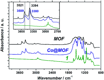
The fact that the Co@MOF catalyst can be recycled multiple times and that no activity arises from the filtrate after isolating the solid confirms that the composite is purely heterogeneous. Noteworthy, both the cobalt precursor, CoBr2 and cobaloxime 1 are soluble at the conditions of the photocatalytic reaction. These data, together with the molecular nature of the cobalt species, imply that the cobalt active sites within Co@MOF are either encapsulated on the basis of the size-selectivity principle or bound to the MOF matrix. The two most likely sites in the MOF structure for coordinating the cobalt centre are the bridging OH-groups within the titanium oxoclusters and the NH2-groups of the organic linkers. The observed shift of amino-stretchings of the framework could indicate such interactions, however a more detailed investigation of these phenomena is needed. Furthermore, EPR analysis of the photoinduced CoII species within Co@MOF reveals a distorted geometry of the high-spin cobalt complex. This spin-state can be explained by: (i) coordination to weak field ligands such as NH2 and/or (ii) distortion of the geometry of the complex confined in the MOF matrix. These observations also support the hypothesis of guest–framework interactions.
Electron paramagnetic resonance experiments on Co@MOF in the dark revealed that the main fraction of cobalt in the catalyst is in its EPR-silent CoIII state that is converted to high-spin CoII species upon illumination. Compared to high-spin CoBr2 (Fig. 7D) that exhibits Lorentzian line broadening and can be described by effective axial gx = gy = 4.8, gz = 2.0 (ESI†), the photoinduced CoII species have lower symmetry and overwhelmingly Gaussian line shape. Both observations imply that a confinement in the MOF affects the geometry/composition of CoII complex and leads to a conformational distribution that requires a more detailed investigation in the future. Moreover, the EPR spectrum of Co@MOF after illumination is markedly different from that of reduced 1 (by reaction with cobaltocene) found in low-spin state evidenced by well-defined hyperfine coupling (Fig. S22†). These findings point towards differences between the MOF-free molecular catalyst 1 and cobalt species found within the Co@MOF composite. Most importantly, the resonance signal of Ti3+ found in the excited pristine NH2-MIL-125(Ti) is not found in the case of Co@MOF proving the successful electron transfer between the different components of the composite.
4.5. Proposed mechanism
On the basis of the EPR observations we speculate that the photoexcited state of the MOF is generated via the following mechanism: upon photon-absorption by the MOF linker, charge separation takes place to generate Ti3+ and a hole at the organic linker. The hole then reacts with the electron donor, TEA, while the electron is rapidly injected into the cobalt species, leading to reduction of CoIII to CoII. We should emphasize that reduction of CoIII centers is generally accepted to be one of the first reaction steps in cobaloxime-catalyzed hydrogen evolution, while the presence of high-spin CoII species is likely to play an important role in photocatalytic activity of the whole system.58 Catalysis taking place at the cobalt metal centres is beyond the scope of this research and thus shown as a dashed arrow in Scheme 3.59In order to demonstrate the feasibility of the proposed mechanism, theoretical47 and experimental data48 for the redox potentials of the building blocks of Co@MOF are depicted in Scheme 3. The catalytic potential for the cobalt complex is well below the LUMO of the MOF, making the electron injection plausible (ESI†). Fluorescence lifetime spectroscopy revealed that the difference in fluorescence lifetimes of Co@MOF composite and the pristine NH2-MIL-125(Ti) was negligible. These observations suggest that the electron transfer from the MOF to the cobalt catalytic centre confirmed by EPR proceeds via the so-called ‘reductive quenching mechanism’.60 The mechanism implies that first the photoexcited MOF is quenched (reduced) by an electron donor, whereas the electron-driven transformations involving the cobaloxime species occur after this process is completed (ESI†).
Summarizing, we have designed a ‘ship-in-a-bottle’ strategy for the synthesis of a Co@MOF composite with remarkable photocatalytic performance in hydrogen evolution under visible light illumination. The organometallic CoIII species within the catalyst are molecular and highly dispersed over the bulk of the MOF matrix. Most of the characterization techniques applied in this work point at the assembly of cobaloxime 1 within the MOF cavities, however the nature of such 1-derived cobalt species within Co@MOF is different from those found in the homogeneous molecular catalyst.
5. Conclusions
In this work we have reported the facile synthesis of a multifunctional catalyst@MOF composite (Co@MOF) through a ‘ship-in-a-bottle’ approach. The resulting Co@MOF composite is a stable material for the efficient photocatalytic production of H2 from water under visible light illumination. Co@MOF can be recycled without loss of activity. Introduction of the molecular Co catalytic active site leads to a 20-fold enhancement in H2 evolution as compared to the pristine NH2-MIL-125(Ti), demonstrating the synergy between a stable, photo-active MOF structure and a 1-derived Co-based proton reduction catalyst for photocatalysis. The extensive characterization of the composite presented in this work points towards the formation of cobaloxime 1 within the pores of the MOF. However, the exact structure of the cobalt species remains unknown. Being a clear example of multifunctional MOF-based systems, the noble metal free Co@MOF catalyst outperforms every MOF based photocatalytic system reported in the literature so far (ESI†). The modular design behind the cooperative action of a photo-active matrix and a catalytically active encapsulated guest will allow for the application of related composites in other photocatalytic applications.Acknowledgements
The Dutch National Research School Combination Catalysis Controlled by Chemical Design (NRSC-Catalysis), the National Research Initiative BioSolarCells, the Foundation for Fundamental Research on Matter (FOM) and RF President's grant MD-276.2014.3 are gratefully acknowledged for funding this research. Dr P.J. Kooyman of DCT/NCHREM, Delft University of Technology, Delft, The Netherlands, is acknowledged for performing the electron microscopy investigations.Notes and references
- N. S. Lewis and D. G. Nocera, Proc. Natl. Acad. Sci. U. S. A., 2006, 103, 15729–15735 CrossRef CAS.
- G. A. Olah, G. K. S. Prakash and A. Goeppert, J. Am. Chem. Soc., 2011, 133, 12881–12898 CrossRef CAS.
- J. Ronge, T. Bosserez, D. Martel, C. Nervi, L. Boarino, F. Taulelle, G. Decher, S. Bordiga and J. A. Martens, Chem. Soc. Rev., 2014, 43, 7963–7981 RSC.
- P. Du and R. Eisenberg, Energy Environ. Sci., 2012, 5, 6012–6021 CAS.
- T. Zhang and W. Lin, Chem. Soc. Rev., 2014, 43, 5982–5993 RSC.
- A. Fujishima and K. Honda, Nature, 1972, 238, 37–38 CrossRef CAS.
- W.-J. Ong, L.-L. Tan, S.-P. Chai, S.-T. Yong and A. Mohamed, Nano Res., 2014, 7, 1528–1547 CrossRef CAS.
- S. Banerjee, S. C. Pillai, P. Falaras, K. E. O'Shea, J. A. Byrne and D. D. Dionysiou, J. Phys. Chem. Lett., 2014, 5, 2543–2554 CrossRef CAS.
- W.-J. Ong, L.-L. Tan, S.-P. Chai, S.-T. Yong and A. R. Mohamed, ChemSusChem, 2014, 7, 690–719 CrossRef CAS.
- J. Yu, J. Low, W. Xiao, P. Zhou and M. Jaroniec, J. Am. Chem. Soc., 2014, 136, 8839–8842 CrossRef CAS.
- J. Zhang, L. Qi, J. Ran, J. Yu and S. Z. Qiao, Adv. Energy Mater., 2014, 4 DOI:10.1002/aenm.201301925.
- J.-L. Wang, C. Wang and W. Lin, ACS Catal., 2012, 2, 2630–2640 CrossRef CAS.
- M. A. Nasalevich, M. van der Veen, F. Kapteijn and J. Gascon, CrystEngComm, 2014, 16, 4919–4926 RSC.
- M. G. Goesten, F. Kapteijn and J. Gascon, CrystEngComm, 2013, 15, 9249 RSC.
- C. Wang, D. Liu and W. Lin, J. Am. Chem. Soc., 2013, 135, 13222–13234 CrossRef CAS.
- S. Bordiga, C. Lamberti, G. Ricchiardi, L. Regli, F. Bonino, A. Damin, K. P. Lillerud, M. Bjorgen and A. Zecchina, Chem. Commun., 2004, 2300–2301 RSC.
- M. Alvaro, E. Carbonell, B. Ferrer, F. Xamena and H. Garcia, Chem.–Eur. J., 2007, 13, 5106–5112 CrossRef CAS.
- F. Xamena, A. Corma and H. Garcia, J. Phys. Chem. C, 2007, 111, 80–85 Search PubMed.
- J. Gascon, M. D. Hernandez-Alonso, A. R. Almeida, G. P. M. van Klink, F. Kapteijn and G. Mul, ChemSusChem, 2008, 1, 981–983 CrossRef CAS.
- H. Khajavi, J. Gascon, J. M. Schins, L. D. A. Siebbeles and F. Kapteijn, J. Phys. Chem. C, 2011, 115, 12487–12493 CAS.
- J. Gascon, A. Corma, F. Kapteijn and F. X. Llabrés i Xamena, ACS Catal., 2014, 4, 361–378 CrossRef CAS.
- M. D. Hernández-Alonso, F. Fresno, S. Suárez and J. M. Coronado, Energy Environ. Sci., 2009, 2, 1231 Search PubMed.
- C. Wang, K. E. Dekrafft and W. Lin, J. Am. Chem. Soc., 2012, 134, 7211–7214 CrossRef CAS.
- Y. Horiuchi, T. Toyao, M. Saito, K. Mochizuki, M. Iwata, H. Higashimura, M. Anpo and M. Matsuoka, J. Phys. Chem. C, 2012, 116, 20848–20853 CAS.
- T. Toyao, M. Saito, Y. Horiuchi, K. Mochizuki, M. Iwata, H. Higashimura and M. Matsuoka, Catal. Sci. Technol., 2013, 3, 2092–2097 CAS.
- D. Sun, Y. Fu, W. Liu, L. Ye, D. Wang, L. Yang, X. Fu and Z. Li, Chem.–Eur. J., 2013, 19, 14279–14285 CrossRef CAS.
- S. Pullen, H. Fei, A. Orthaber, S. M. Cohen and S. Ott, J. Am. Chem. Soc., 2013, 135, 16997–17003 CrossRef CAS.
- C. Wang, J. L. Wang and W. Lin, J. Am. Chem. Soc., 2012, 134, 19895–19908 CrossRef CAS.
- C. Wang, Z. Xie, K. E. deKrafft and W. Lin, J. Am. Chem. Soc., 2011, 133, 13445–13454 CrossRef CAS.
- W. Lubitz, C. J. Winscom, H. Diegruber and R. Möseler, Z. Naturforsch., A: Phys. Sci., 1987, 42, 970–986 CAS.
- J. Niklas, K. L. Mardis, R. R. Rakhimov, K. L. Mulfort, D. M. Tiede and O. G. Poluektov, J. Phys. Chem. B, 2012, 116, 2943–2957 CrossRef CAS.
- E. Uhlig and M. Friedrich, Z. Anorg. Allg. Chem., 1966, 343, 299–307 CrossRef.
- G. Costa, G. Mestroni and E. de Savorgnani, Inorg. Chim. Acta, 1969, 3, 323–328 CrossRef CAS.
- J. Juan-Alcaniz, J. Gascon and F. Kapteijn, J. Mater. Chem., 2012, 22, 10102–10118 RSC.
- S. Vaesen, V. Guillerm, Q. Yang, A. D. Wiersum, B. Marszalek, B. Gil, A. Vimont, M. Daturi, T. Devic, P. L. Llewellyn, C. Serre, G. Maurin and G. De Weireld, Chem. Commun., 2013, 49, 10082–10084 RSC.
- N. M. Muresan, J. Willkomm, D. Mersch, Y. Vaynzof and E. Reisner, Angew. Chem., Int. Ed., 2012, 51, 12749–12753 CrossRef CAS.
- M. A. Nasalevich, M. G. Goesten, T. J. Savenije, F. Kapteijn and J. Gascon, Chem. Commun., 2013, 49, 10575–10577 RSC.
- J. Huang, K. L. Mulfort, P. Du and L. X. Chen, J. Am. Chem. Soc., 2012, 134, 16472–16475 CrossRef CAS.
- J. Säuberlich, O. Brede and D. Beckert, J. Phys. Chem. A, 1997, 101, 5659–5665 CrossRef.
- H. Drulis, K. Dyrek, K. P. Hoffmann, S. K. Hoffmann and A. Weselucha-Birczynska, Inorg. Chem., 1985, 24, 4009–4012 CrossRef CAS.
- J. Long, S. Wang, Z. Ding, S. Wang, Y. Zhou, L. Huang and X. Wang, Chem. Commun., 2012, 48, 11656–11658 RSC.
- A. Bencini, I. Bertini, G. Canti, D. Gatteschi and C. Luchinat, J. Inorg. Biochem., 1981, 14, 81–93 CrossRef CAS.
- F. Jeremias, V. Lozan, S. K. Henninger and C. Janiak, Dalton Trans., 2013, 42, 15967–15973 RSC.
- S.-N. Kim, J. Kim, H.-Y. Kim, H.-Y. Cho and W.-S. Ahn, Catal. Today, 2013, 204, 85–93 CrossRef CAS.
- M. De Miguel, F. Ragon, T. Devic, C. Serre, P. Horcajada and H. García, ChemPhysChem, 2012, 13, 3651–3654 CrossRef CAS.
- C. H. Hendon, D. Tiana, M. Fontecave, C. Sanchez, L. D'arras, C. Sassoye, L. Rozes, C. Mellot-Draznieks and A. Walsh, J. Am. Chem. Soc., 2013, 135, 10942–10945 CrossRef CAS.
- K. T. Butler, C. H. Hendon and A. Walsh, J. Am. Chem. Soc., 2014, 136, 2703–2706 CrossRef CAS.
- P.-A. Jacques, V. Artero, J. Pécaut and M. Fontecave, Proc. Natl. Acad. Sci. U. S. A., 2009, 106, 20627–20632 CrossRef CAS.
- L. A. Berben and J. C. Peters, Chem. Commun., 2010, 46, 398–400 RSC.
- W. R. McNamara, Z. Han, C.-J. Yin, W. W. Brennessel, P. L. Holland and R. Eisenberg, Proc. Natl. Acad. Sci. U. S. A., 2012, 109, 15594–15599 CrossRef CAS.
- L. Tong, R. Zong and R. P. Thummel, J. Am. Chem. Soc., 2014, 136, 4881–4884 CrossRef CAS.
- M. Giorgetti, M. Berrettoni, I. Ascone, S. Zamponi, R. Seeber and R. Marassi, Electrochim. Acta, 2000, 45, 4475–4482 CrossRef CAS.
- M. Krivec, R. Dillert, D. W. Bahnemann, A. Mehle, J. Strancar and G. Drazic, Phys. Chem. Chem. Phys., 2014, 16, 14867–14873 RSC.
- F. Lakadamyali and E. Reisner, Chem. Commun., 2011, 47, 1695–1697 RSC.
- F. Lakadamyali, A. Reynal, M. Kato, J. R. Durrant and E. Reisner, Chem.–Eur. J., 2012, 18, 15464–15475 CrossRef CAS.
- Y. Ma, X. Wang, Y. Jia, X. Chen, H. Han and C. Li, Chem. Rev., 2014, 114, 9987–10043 CrossRef CAS.
- N. Bao, L. Shen, T. Takata and K. Domen, Chem. Mater., 2007, 20, 110–117 CrossRef.
- A. Mukherjee, O. Kokhan, J. Huang, J. Niklas, L. X. Chen, D. M. Tiede and K. L. Mulfort, Phys. Chem. Chem. Phys., 2013, 15, 21070–21076 RSC.
- A. Bhattacharjee, E. S. Andreiadis, M. Chavarot-Kerlidou, M. Fontecave, M. J. Field and V. Artero, Chem.–Eur. J., 2013, 19, 15166–15174 CrossRef CAS.
- V. Artero, M. Chavarot-Kerlidou and M. Fontecave, Angew. Chem., Int. Ed., 2011, 50, 7238–7266 CrossRef CAS.
Footnotes |
| † Electronic supplementary information (ESI) available: Experimental methods, spectroscopic and analytical data on catalyst and assembly characterization, photocatalysis and recycling results. This material is available free of charge via the internet at See DOI: 10.1039/c4ee02853h |
| ‡ These authors contributed equally. |
| This journal is © The Royal Society of Chemistry 2015 |

