NaTiO2: a layered anode material for sodium-ion batteries†
Di
Wu‡
a,
Xin
Li‡
b,
Bo
Xu
b,
Nancy
Twu
b,
Lei
Liu
b and
Gerbrand
Ceder
*b
aDepartment of Mechanical Engineering, Massachusetts Institute of Technology, Cambridge, MA 01239, USA
bDepartment of Materials Science and Engineering, Massachusetts Institute of Technology, Cambridge, MA 01239, USA. E-mail: gceder@mit.edu
First published on 28th October 2014
Abstract
We report on layered NaTiO2 as a potential anode material for Na-ion batteries. The material is prepared from only earth-abundant elements, delivers 152 mA h g−1 of reversible capacity at C/10 rate, shows excellent cyclability with capacity retention over 98% after 60 cycles, and high rate capability. Furthermore, in situ X-ray diffraction analysis reveals a reversible O3–O′3 phase transition, including an unusual lattice parameter variation coupled to complicated Na vacancy orderings in a series of 2nd order phase transitions.
Broader contextLithium-ion batteries are currently the energy storage technology of choice in portable electronic devices and electric vehicles. In recent years, sodium-ion batteries have been actively restudied as a promising alternative because of the abundance of sodium resources and the high capacity cathodes available. But as graphitic carbon can not be used as anode material, as it is in lithium batteries, the design of the novel Na-ion anode materials with high capacity and cycling-stability is critical for the advancement of Na-ion batteries. In this paper, we successfully synthesized and tested the layered NaTiO2 compound with high reversible capacity and excellent cycling performance. The details of structural evolution and fundamental intercalation mechanism upon charging and discharging are revealed by in situ X-ray diffraction. Our findings will facilitate the development of novel electrode materials for sodium-ion batteries. |
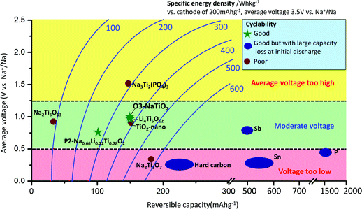
Sodium-ion batteries have attracted increasing attention for large-scale energy storage applications because of the natural abundance and low cost of sodium resources.1–3 Na has a larger ionic radius (0.97 Å) and higher redox potential (−2.71 V vs. SHE) than Li, and the interactions between Na ions and the host crystal structures can vary greatly from those of their Li analogues,4 which is why Na-intercalation in compounds is often very different from the behavior of the Li-analogues.1–4 The most commonly applied anode material in Li-ion batteries is graphite, for which Na-ion intercalation is thermodynamically not favourable.5 Currently, reports on applicable anode materials for Na-ion batteries are limited in the literature,1–3 as summarized in Fig. 1. Hard carbon exhibits a reversible capacity of 240 mA h g−1 with stable cycle performance in a NaClO4/EC:DEC electrolyte.6 However, its density is very low, and most of the usable capacity is located near the sodium plating voltage, leading to potential safety concerns. Alloys such as Sn and Sb have been shown to exhibit very high storage capacities (∼600 mA h g−1); however, undesired large volume change during sodium insertion and extraction makes it challenging to attain satisfactory cyclability without the use of special binders and electrolyte additives, and to achieve high enough effective energy density.7–10 In addition, alloy anodes suffer from large capacity losses (150–500 mA h g−1) during initial sodiation. Oxides have also been explored as potential electrode candidates for Na-ion batteries.1–3,11 Na2Ti3O7 delivers an initial capacity of more than 200 mA h g−1; however, its cycling performance is not satisfactory.12,13 Li4Ti5O12 can deliver a reversible capacity of 155 mA h g−1 in a displacement reaction with Na, and shows good cyclability using carboxymethyl-cellulose as the binder.14 A new anode material, P2-Na0.66[Li0.22Ti0.78]O2, exhibits excellent cyclability partly due to its negligible volume change (0.77%) during sodium insertion and extraction; however, the usable capacity is limited to 100 mA h g−1, corresponding to 1/3 Na per formula unit.15
Research on layered NaMO2-type oxides (M = 3d transition metal, such as Ti, V, Cr, Mn, Fe, Co, Ni) as intercalation electrode materials began in the 1980s but has recently received renewed interest.16–29 Using advances in electrolytes, a re-investigation of NaMnO2 and NaNiO2 demonstrated that these compounds can reversibly exchange approximately 0.8 Na and 0.5 Na,22,23 respectively, noticeably larger than the results previously reported in the 1980s.18,20 In the 1980s, Mazzaz et al. examined the electrochemical performance of NaTiO2 (ref. 19) as a potential anode intercalation material. However, limited cyclable capacity corresponding to ≈0.3 Na was reported. A recent DFT calculation hinted at an unusually high barrier of 0.75 eV for Na migration in NaTiO2,15 which would prevent intercalation at any reasonable rate.
In this paper the performance of NaTiO2 is re-investigated. In contrast to the previous work, an electrochemical reversible capacity of 152 mA h g−1 is achieved, corresponding to approximately 0.5 Na exchange, with excellent cyclability and good rate capability. Our DFT simulation reveals very low Na diffusion barriers, consistent with the excellent electrochemical performance. In situ X-ray diffraction (XRD) reveals a complicated process of superstructure evolution coupled to an unusual lattice parameter variation during Na de-intercalation. Understanding this process may further help in the design of better Na-intercalation electrode materials.
Results
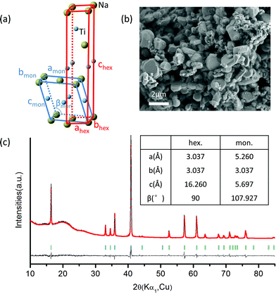
NaTiO2 was synthesized via a solid-state reaction using Na metal to reduce anatase TiO2.19 The XRD spectrum and SEM image of the as-prepared NaTiO2 powder are presented in Fig. 2, which shows a pure O3-type NaTiO2 phase of space group R-3m with particle size of approximately 1 to 2 μm. The “O3” nomenclature is after Delmas30 and indicates that the Na ions are octahedrally coordinated by oxygen and have a repetition period of three transition metal stacking along the c-axis.30 Rietveld refinement gives hexagonal lattice parameters of a = b = 3.037(1) Å and c = 16.260(2) Å, which is consistent with previous reports.19,31 Another equivalent definition of the unit cell, which is often used to describe the phase with monoclinic distortion,16,29 is illustrated in Fig. 2(a) together with the hexagonal definition. The corresponding lattice parameters of pristine NaTiO2 to the two equivalent definitions are listed in the inset table in Fig. 2(c). Using an approach developed recently in the NaCoO2 system,32 we find the Na content of the compound by comparing the c lattice parameter with the ones measured by in situ XRD at different Na intercalation levels (Fig. S1†). This analysis yields a composition close to Na0.99TiO2, which is consistent with previous reports.31,33A battery was assembled as NaTiO2|1 M NaPF6 in EC![[thin space (1/6-em)]](https://www.rsc.org/images/entities/char_2009.gif) :
:![[thin space (1/6-em)]](https://www.rsc.org/images/entities/char_2009.gif) DEC = 1
DEC = 1![[thin space (1/6-em)]](https://www.rsc.org/images/entities/char_2009.gif) :
:![[thin space (1/6-em)]](https://www.rsc.org/images/entities/char_2009.gif) 1|Na. The electrolyte was dehydrated using molecular sieves, with details provided in the Methods. The electrochemical performance of NaTiO2 is shown in Fig. 3. NaTiO2 delivers 152 mA h g−1 of reversible capacity in the voltage range of 0.6–1.6 V, corresponding to approximately 52% of the theoretical capacity based on a single-electron redox process of the Ti3+/Ti4+ couple (theoretical capacity of 293.3 mA h g−1 calculated based on the partial desodiated compound Na0.5TiO2). The capacity is among the highest of anode intercalation compounds, as evidenced by Fig. 1. The strong similarity between the discharge and charge curves and the low 0.02 V hysteresis at the voltage plateau shown in Fig. 3(a) indicates that the intercalation process is reversible with only small polarization.
1|Na. The electrolyte was dehydrated using molecular sieves, with details provided in the Methods. The electrochemical performance of NaTiO2 is shown in Fig. 3. NaTiO2 delivers 152 mA h g−1 of reversible capacity in the voltage range of 0.6–1.6 V, corresponding to approximately 52% of the theoretical capacity based on a single-electron redox process of the Ti3+/Ti4+ couple (theoretical capacity of 293.3 mA h g−1 calculated based on the partial desodiated compound Na0.5TiO2). The capacity is among the highest of anode intercalation compounds, as evidenced by Fig. 1. The strong similarity between the discharge and charge curves and the low 0.02 V hysteresis at the voltage plateau shown in Fig. 3(a) indicates that the intercalation process is reversible with only small polarization.
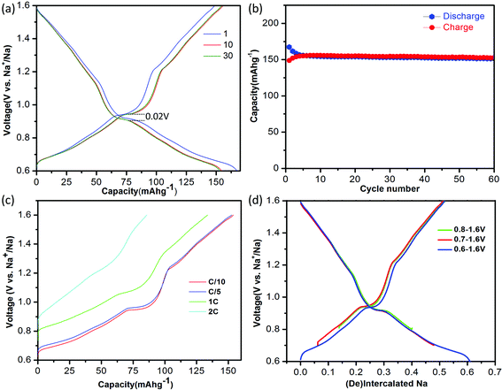 | ||
| Fig. 3 Electrochemical performance of NaTiO2. (a) The 1st, 10th and 30th galvanostatic charge/discharge curves at a current rate of C/10 in the voltage range of 0.6–1.6 V versus Na+/Na. The voltage curve of the battery pre-discharged to 0.6 V is not shown for simplicity (see ESI Fig. S1(b)†). (b) Cyclability. The charge/discharge capacity versus cycle number at a current rate of C/10. (c). Rate capability. The battery was discharged to 0.6 V at a current rate of C/20 and then charged to 1.6 V at different rates from C/10 to 2 C. (d) Comparison of the amount of cycled Na in voltage windows with lower cut-off voltages from 0.6–0.8 V. | ||
When raising the lower voltage cutoff, a specific capacity of approximately 109 mA h g−1 in the voltage range of 0.8–1.6 V (0.37 Na) is achieved as shown in Fig. 3(d), which is slightly larger than the previously reported value.19 It is noteworthy that in the low-voltage range from 0.6 V to 0.8 V, NaTiO2 delivers an additional capacity of approximately 45 mA h g−1 (0.15 Na). We notice that the open-circuit-voltages of as-prepared batteries fall into this voltage window, which might be due to different levels of Na self-deintercalation from battery to battery. However, the capacity in the low-voltage range derives from a reversible intercalation reaction, as confirmed by the continuous decrease of the slab distance of NaxTiO2 upon Na intercalation down to 0.6 V (Fig. S1†) and a reverse process upon Na de-intercalation identified by in situ XRD. Identification of this reversible electrochemical reaction in the low voltage range not only results in capacity that is 50% higher than previous reports,19 but more importantly, it gives the correct relation between Na composition and electrochemical voltage for further structure and superstructure analysis.
If the lower cutoff voltage is further decreased to 0.55 V, cycle life decreases as demonstrated in Fig. S2,† likely due to the electrolyte decomposition.6 If charged above 1.6 V, an irreversible structure modification is observed in our in situ XRD results (Fig. S3†), in accordance with a previous ex situ XRD study.19 We thus restricted the voltage window to 0.6–1.6 V. Fig. 3(b) shows that in the 0.6–1.6 V voltage range NaTiO2 retains 98% of its initial capacity after 60 cycles at a current rate of C/10. The coulombic efficiency is approximately 82% in the initial cycle and 99.5% in the later cycles, which is comparable to the behavior of some of the best anode materials.14,15
The rate capability of NaTiO2 is shown in Fig. 3(c). At C/5 rate, a charge capacity of 152 mA h g−1 (99% of C/10 rate) is achieved with excellent cyclability. Even at 1 C rate, the compound still delivers a large charge capacity of 133.6 mA h g−1 (87.9% of C/10 rate) with a small polarization of the voltage curve. Note that special treatment of the electrode material such as carbon coating or nanosizing may further improve the electrochemical performance from the micrometer-sized NaTiO2 particles.34 The average voltage of sodium insertion into NaTiO2 is approximately 1 V, which is higher than previous report for P2-Na0.66[Li0.22Ti0.78]O2.15 However, as observed in Fig. 1 and ESI Table 1,† full cells assembled with NaTiO2 anode and appropriate cathodes could still achieve a considerably higher energy density due to the relatively larger capacity of NaTiO2.
The structural evolution in NaxTiO2 upon electrochemical de-intercalation as measured by in situ XRD is illustrated in Fig. 4. In the 0.6–0.94 V range, the positions of the diffraction peaks shift continuously, suggesting a typical single-phase domain. XRD refinement reveals that the O3 phase with hexagonal R-3m symmetry is maintained in the corresponding composition range of 1 > x > 0.76 in NaxTiO2. Upon further sodium deintercalation at the 0.94 V voltage plateau, the (003)hex diffraction peak broadens together with the appearance of a new adjacent peak at lower angle, and the split of (01-4)hex diffraction peak into two peaks, suggesting a two-phase domain, which is observed to be reversible in the discharge process.
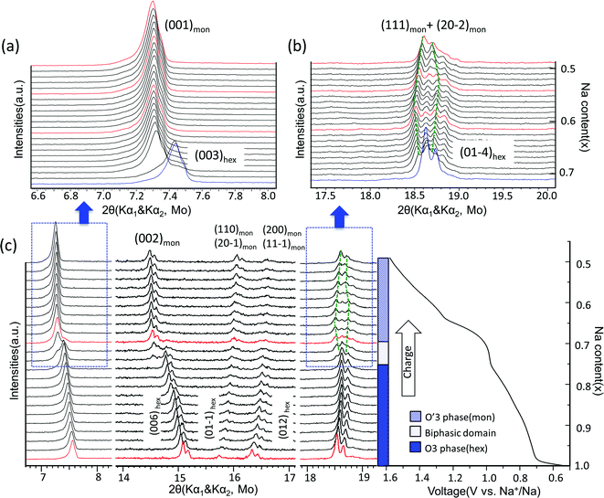 | ||
| Fig. 4 Structural evolution during electrochemical desodiation of O3–NaTiO2. (a) and (b) In situ X-ray diffraction patterns recorded during the PITT experiments centered around the (003)hex, (001)mon reflections and (01-4)hex, (111)mon + (20-2)mon reflections, respectively. Note that X-ray source is Mo with Kα1 and Kα2. The green dash lines illustrate the evolution of Kα1 reflections in O′3 phase region. The red XRD spectra are further explained in Fig. 6. (c) In situ XRD patterns during the first galvanostatic charge at a current rate of C/20 in the voltage range between 0.5 V and 1.6 V. The regions corresponding to (a) and (b) are marked by the dashed boxes. Note that in the entire 2θ range, preferred orientation for (00l) reflections exists because the electrode films were prepared using a dry method that involved multiple pressing and rolling processes. | ||
The diffraction peaks of the new phase can be indexed by the O′3-type layered structure with monoclinic space group C2/m.19,30 Rather than the 108° β angle in the O3 phase (converted to the monoclinic definition as illustrated in Fig. 2(a)), the β angle of the O′3 phase is approximately 106°, displaying a monoclinic distortion, which features the splitting of the (01-4)hex reflection into (111)mon and (20-2)mon reflections as shown in Fig. 4. When charged close to 1.54 V or Na0.5TiO2, the distance between the (111)mon and (20-2)mon peaks decreases and they tend to merge, indicating a transform back toward the hexagonal structure.19,33 Cyclic voltammetry results at various sweep rates and the first differential capacity curve (dQ/dV) further confirm a typical intercalation reaction mechanism, as shown in Fig. S4.†
The corresponding evolution of lattice parameters during sodium deintercalation is illustrated in Fig. 5. In the O3 phase region, the shift of the (003) diffraction peak to lower 2θ angles demonstrates that the interslab distance d003, which is 1/3 of the chex parameter, increases due to the loss of cohesiveness when sodium ions are extracted from the interslab space,30 as illustrated in Fig. 5(a). In addition, due to the oxidation of titanium, the ahex parameter, which measures the average Ti–Ti ion distances decreases.
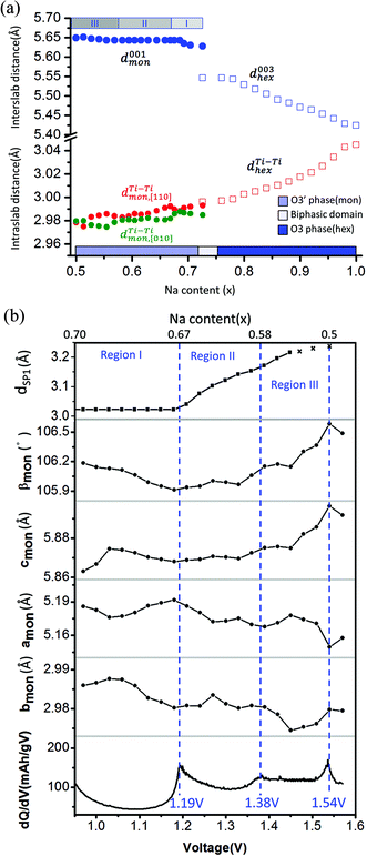 | ||
Fig. 5 (a) Interslab and intraslab distances in the NaxTiO2 phases. The interplanar distances are calculated using the following equations: d003hex = chex/3, dTi–Tihex = ahex, d001mon = cmon![[thin space (1/6-em)]](https://www.rsc.org/images/entities/char_2009.gif) sin sin![[thin space (1/6-em)]](https://www.rsc.org/images/entities/char_2009.gif) βmon, βmon,  , dTi–Timon,[010] = bmon. (b) Correlation between the evolution of lattice parameters of the O′3 phase and differential capacity curve in the voltage range of 0.95 V–1.57 V. The amon, bmon, cmon and βmon cell parameters were determined from in situ X-ray diffraction patterns collected during PITT charge with a 4 h scan per spectrum and a 0.03 V voltage step. The cell parameters were calculated using a conventional monoclinic unit cell with C2/m symmetry. Regions I, II, and III are divided by the three inflection points on the 1st differential curve of capacity over voltage. dSP1 represents the interplanar distance of the strongest superstructure peak labeled in Fig. 6. , dTi–Timon,[010] = bmon. (b) Correlation between the evolution of lattice parameters of the O′3 phase and differential capacity curve in the voltage range of 0.95 V–1.57 V. The amon, bmon, cmon and βmon cell parameters were determined from in situ X-ray diffraction patterns collected during PITT charge with a 4 h scan per spectrum and a 0.03 V voltage step. The cell parameters were calculated using a conventional monoclinic unit cell with C2/m symmetry. Regions I, II, and III are divided by the three inflection points on the 1st differential curve of capacity over voltage. dSP1 represents the interplanar distance of the strongest superstructure peak labeled in Fig. 6. | ||
To improve the precision of the calculated lattice parameters and observe clearly the superstructure evolution in the O′3 region, X-ray spectra were collected while the in situ battery was held potentiostatically at each voltage step between 0.97 V and 1.57 V, with a 0.03 V step size. In the O′3 single-phase region, the (001)mon and (002)mon peaks remain in the same 2θ position (Fig. 4(a)), corresponding to a constant interslab distance upon deintercalation shown in Fig. 5(a). In addition to the phenomena of constant slab distance, the in plane Ti–Ti ion distance continuously modulates upon desodiation within a narrow range of 0.02 Å in the O′3 phase, as also illustrated in Fig. 5(a). In Fig. 5(b), the variations of lattice parameters of the O′3 phase at different PITT voltages were compared with the 1st derivative of the galvanostatic charge capacity over voltage, which reveals three inflection points at 1.19 V, 1.38 V and 1.54 V dividing the O′3 phase into three regions. The 2nd derivative of the capacity over voltage is discontinuous at these three voltage points, indicating 2nd order phase transitions.35 Compared with the typical trend of lattice parameter evolution observed in the O3 single phase region, it is quite unusual that in the O′3 phase region, the inter- and intra-slab distances vary in such a narrow range upon Na de-intercalation, which may indicate the existence of some unusual Na orderings.
Superstructure evolution with varying sodium content is in fact observed using in situ XRD as shown in Fig. 6, which reveals the presence of additional weak Bragg peaks that are characteristic of superstructures in the 12°–14° and 17°–18° 2θ range. The strongest superstructure peak appears at approximately 13.5° (SP1) and remains at the same angle in region I until the battery is charged up to the inflection point at 1.19 V (corresponding to ∼Na0.67TiO2). Beyond the inflection point, this peak starts to shift to lower 2θ angles during the desodiation process in region II. A similar behavior is simultaneously observed for the superstructure peaks at approximately 17.9° (SP2). These superstructure peaks undergo a very significant shift, their rate of change in diffraction angle being an order of magnitude larger than the major hkl peak shift of the O′3 phase, as shown for SP1 in region II of Fig. 5(b) and 6. When the in situ cell is charged beyond the second inflection point on the voltage curve (corresponding to ∼1.38 V or Na∼0.58TiO2) into region III, the intensities of the superstructure peaks observed in the previous two regions gradually weaken. After the in situ cell is charged up to the third inflection point on the voltage curve (corresponding to 1.54 V or Na∼0.5TiO2), all the superstructure peaks observed in regions I and II disappear from the in situ XRD spectra.
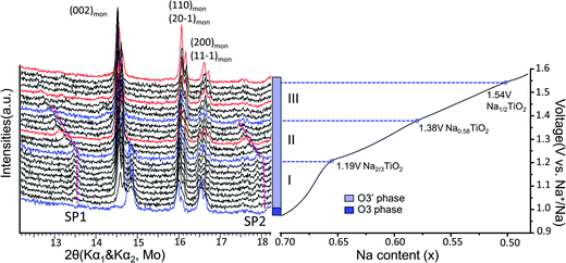 | ||
| Fig. 6 Superstructure evolution from in situ XRD during electrochemical test. In situ XRD was collected during PITT charge of 0.03 V step size with 4 h (blue and black) or 10 h (red) scan per spectrum. The purple dashed lines represent the evolution of the superstructures (SP1 and SP2). The galvanostatic charge curve is shown on the right to illustrate the three regions divided by the inflection points explained in Fig. 5, as represented by the blue XRD spectra and dashed lines. | ||
Discussion
In contrast to a previous report we find a reversible capacity of 152 mA h g−1 for O3 NaTiO2 which corresponds to the exchange of ≈0.5 Na in the voltage window 0.6–1.6 V. The increase in capacity from a previous report19 is due to the widened low voltage window that is likely achieved by minimizing the water concentration in the recent electrolyte.The rate capability of NaTiO2 is remarkably high, considering the micro-sized particles. This observation led us to re-investigate the previously reported diffusion barrier for Na in NaTiO2. As Fig. 7 demonstrates, our DFT calculations find a Na migration barrier less than 224 meV in both O3 and O′3 phases, which is remarkably low, but consistent with the excellent rate capability observed experimentally. The calculated diffusion barrier of 750 meV reported earlier14 may not have considered the di-vacancy diffusion mechanism which is known to be the operating mechanism for Na and Li migration in all O3 compounds.36,37 The rate capability of NaTiO2 is better than some other O3-type layered materials, such as NaMnO2, NaCoO2 and NaNiO2, which all have stepwise voltage profiles.21–23 It has been speculated that the two-phase boundary movement at these voltage plateaus slows down the Na insertion kinetics.28 Our in situ XRD results of NaTiO2 in Fig. 4 indicate that most regions are single phase, yielding a smooth voltage profile, while the two-phase reaction is limited to a short 0.94 V plateau, at which the O3 phase transforms into the O′3 phase through a monoclinic distortion.
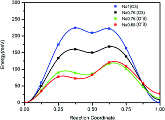 | ||
| Fig. 7 Calculated diffusion barrier for Na in the O3 and O′3 phases using the di-vacancy mechanism. Details of the calculation are given in the Methods. | ||
The phenomenon of constant interslab distance in the O′3 single-phase region upon deintercalation is very unusual. Normally, the interslab distance changes continuously in the single-phase domain of layered compounds, but remains constant in the biphasic domain,14,15,24–26,38 similar to the chex parameter variation of the O3 NaxTiO2 phase discussed above. Furthermore, this phenomenon can not be explained by the commensurate Na orderings or superstructures that are often observed,26,27 as for a given commensurate superstructure the positions of superstructure peaks can not shift beyond the level of the lattice parameter variation. The large shift of superstructure peaks as shown in Fig. 5(b) and 6 is therefore likely to come from the change in modulation period of the ordering itself, as is sometimes observed in metallic alloys.39 The fact that the peak shift in XRD is continuous points towards rather uncommon incommensurate Na orderings, as has been observed in a few other layered oxides.40,41 If the modulation includes a composition component, the variation of modulation wavelength may be able to accommodate the complete Na composition range of the O′3 phase, without any significant change in slab spacing.
The correlation between the electrochemical voltage profile and the evolution of the ordering superstructure shown in Fig. 6 suggests that the O′3 region actually corresponds to three domains with different superstructure modulations. Domain I, the inception stage of the single O′3 phase, may correspond to the formation of Na2/3TiO2 ordering. In domain II, the significant shift of the superstructure peaks may indicate an unusual incommensurate superstructure,40,41 which shares an ordering pattern similar to Na2/3TiO2 but with increasing modulation length and decreasing Na content down to Na0.58TiO2. Domain III might be a “biphasic domain” of two competing phases of the incommensurate Na2/3TiO2-like ordering with decreasing Na content from 0.58 further down to 0.5 and the possible formation of a solid solution phase. At 50% desodiation level, the superstructure phase likely transforms back into a solid solution phase. Moreover, no voltage plateau or step was observed around Na0.5TiO2, giving no evidence for the existence of a typical Na0.5TMO2 ordering.29 Therefore, the constant 1st derivative of the capacity over voltage in region III of Fig. 5(b) may suggest the competition between the superstructure phase observed by our in situ XRD and a solid solution phase upon Na de-intercalation, consistent with the observed transition from the monoclinic phase back to the rhombohedral phase.
It is worth noting that the actual percentage of lattice parameter variations in the layered O3 or P2 compounds is usually twice larger than the calculated volume expansion rate, with the shrinkage in the ab plane compensated in part by expansion in the c direction, corresponding to an obvious elongation of the crystal.15 The special modulation of superstructures in the O′3 phase region of NaxTiO2, however, is coupled to the extremely small variation of the lattice parameters, as observed in Fig. 5, corresponding to a negligible volume expansion of approximately 0.4% (Fig. S5†). The excellent cyclability of NaTiO2 might partially originate from its peculiar structural evolution. Similar large shifts of superstructure peaks coupled to very small lattice parameter variations in the single-phase domains were observed in certain composition ranges of NaxVO2,26 which we believe may also be caused by an incommensurate superstructure evolution. Thus, the phenomenon is not limited to the Ti based system. Designing layered compounds that can show incommensurate superstructure or its competition with a solid solution phase in a large Na composition range might be a challenging but promising direction for both cathode and anode applications with improved structural stability upon Na intercalation.
Conclusion
In summary, O3-NaTiO2 was synthesized and tested electrochemically as an anode material for sodium-ion batteries. Approximately 0.5 Na can be reversibly intercalated in NaTiO2, corresponding to a reversible capacity of 152 mA h g−1. To achieve high capacity and the best cyclability, the optimal voltage window for galvanostatic cycling is 0.6–1.6 V. In addition, the sodium insertion/extraction mechanism was investigated using in situ X-ray diffraction. A reversible O3 to O′3 phase transition was observed. Special Na vacancy orderings were observed to be coupled with the unusual lattice parameter variation, which yields a constant interslab distance and slightly changing in-plane Ti–Ti distance in the O′3 phase. With its high capacity and excellent cyclability, NaTiO2, which consists only of earth-abundant elements, is a promising intercalation anode material for sodium-ion batteries.Methods
Solid-state synthesis of NaTiO2
O3-type NaTiO2 was synthesized via a solid-state reaction. TiO2 anatase (Sigma Aldrich, 99.99%) and freshly cut Na (Sigma Aldrich, 99.95%) with 10% excess were placed in a Swagelok stainless steel tube, which was sealed in an argon-filled glove box. The tube was then fired at 920 °C for 12 hours in a flow of argon gas. After cooling, the tube was opened in the glove box to prevent exposure to air and moisture.Material characterization
The X-ray diffraction (XRD) patterns were collected on a Rigaku RU300 rotating anode diffractometer equipped with Cu Kα1 radiation in the 2θ range of 10°–85°. All the samples were sealed with Kapton film to avoid air exposure. Rietveld refinement and profile matching of the powder diffraction data of the as-prepared NaTiO2 were performed using PANalytical X'Pert High Score Plus. The morphology of the as-prepared NaTiO2 was examined using a Zeiss Merlin scanning electron microscope.Electrochemical tests
The active material of NaTiO2, the conductive agent carbon black (Timcal, Super P) and polyethylenetetrafluoride (PTFE) binder were manually mixed in a glove box with a weight ratio of 80![[thin space (1/6-em)]](https://www.rsc.org/images/entities/char_2009.gif) :
:![[thin space (1/6-em)]](https://www.rsc.org/images/entities/char_2009.gif) 15
15![[thin space (1/6-em)]](https://www.rsc.org/images/entities/char_2009.gif) :
:![[thin space (1/6-em)]](https://www.rsc.org/images/entities/char_2009.gif) 5 and then rolled into a thin film. The electrolyte was prepared by dissolving anhydrous NaPF6 (98%, Sigma Aldrich) into ethylene carbonate:diethylcarbonate (EC:DEC) solution (anhydrous Sigma Aldrich, 1
5 and then rolled into a thin film. The electrolyte was prepared by dissolving anhydrous NaPF6 (98%, Sigma Aldrich) into ethylene carbonate:diethylcarbonate (EC:DEC) solution (anhydrous Sigma Aldrich, 1![[thin space (1/6-em)]](https://www.rsc.org/images/entities/char_2009.gif) :
:![[thin space (1/6-em)]](https://www.rsc.org/images/entities/char_2009.gif) 1 in volume ratio). The as-prepared electrolyte exhibited a water level of approximately 5 ppm and was further dehydrated using 20 wt% molecular sieves with continuous rotation for two days. A Na metal film was used as the counter electrode. Swagelok cells were assembled in an argon-filled glove box with the oxygen and moisture levels being less than 0.1 ppm. The cells were tested on a Maccor 2200 or Arbin BT2000 operating at room temperature. The loading density of the active material was maintained at approximately 3 mg cm−2.
1 in volume ratio). The as-prepared electrolyte exhibited a water level of approximately 5 ppm and was further dehydrated using 20 wt% molecular sieves with continuous rotation for two days. A Na metal film was used as the counter electrode. Swagelok cells were assembled in an argon-filled glove box with the oxygen and moisture levels being less than 0.1 ppm. The cells were tested on a Maccor 2200 or Arbin BT2000 operating at room temperature. The loading density of the active material was maintained at approximately 3 mg cm−2.
In situ X-ray diffraction
In situ X-ray diffraction experiments during electrochemical testing of the batteries were performed on a Bruker D8 Advance Da Vinci Mo-source diffractometer scanned between 6.5°–30.5° 2θ range. An in situ battery was designed with a Be window for X-ray penetration. The battery was configured with a NaTiO2 electrode as the working electrode, sodium as the counter electrode, 1 M NaPF6/EC:DEC as the electrolyte and glass fiber as the separator. The charge/discharge of the in situ battery was performed on a Solartron electrochemical potensiostat in the voltage range of 0.5–1.6 V at a current rate of C/20, or during potentiostatic intermittent titration technique (PITT) charge with a step size of 30 mV and step duration of 4 or 10 hours.DFT simulation
First principles calculations were performed in Generalized Gradient Approximations (GGA) to Density Functional Theory (DFT) using Vienna ab initio simulation package (VASP). Na diffusion barriers were calculated using the Nudged Elastic Band (NEB) method with the di-vacancy diffusion mechanism implemented in a 3 × 3 × 2 supercell corresponding to the composition of Na8/9TiO2. Na diffusion barriers in Na8/9TiO2 were investigated with four different lattice parameters. Firstly, the lattice parameters of fully sodiated phase O3 Na1TiO2 were fully relaxed by DFT and then fixed for NEB calculations. Three other lattice parameters are obtained by magnifying DFT relaxed O3 Na1TiO2 lattice parameters proportional to the experimental ratios (obtained from in situ XRD) between O3 Na1TiO2, O3 Na0.76TiO2, O′3 Na0.76TiO2 and O′3 Na0.68TiO2.Acknowledgements
This work was supported by the Samsung Advanced Institute of Technology.References
- S.-W. Kim, D.-H. Seo, X. Ma, G. Ceder and K. Kang, Adv. Energy Mater., 2012, 2, 710 CrossRef CAS.
- H. Pan, Y.-S. Hu and L. Chen, Energy Environ. Sci., 2013, 6, 2338 CAS.
- M. Dahbi, N. Yabuuchi, K. Kubota, K. Tokiwa and S. Komaba, Phys. Chem. Chem. Phys., 2014, 16, 15007 RSC.
- S. P. Ong, V. L. Chevrier, G. Hautier, A. Jain, C. Moore, S. Kim, X. Ma and G. Ceder, Energy Environ. Sci., 2011, 4, 3680 CAS.
- P. Ge and M. Fouletier, Solid State Ionics, 1988, 30, 1172 CrossRef.
- S. Komaba, W. Murata, T. Ishikawa, N. Yabuuchi, T. Ozeki, T. Nakayama, A. Ogata, K. Gotoh and K. Fujiwara, Adv. Funct. Mater., 2011, 21, 3859 CrossRef CAS.
- A. Darwiche, C. Marino, M. T. Sougrati, B. Fraisse, L. Stievano and L. Monconduit, J. Am. Chem. Soc., 2012, 134, 20805 CrossRef CAS PubMed.
- S. Komaba, Y. Matsuura, T. Ishikawa, N. Yabuuchi, W. Murata and S. Kuze, Electrochem. Commun., 2012, 21, 65 CrossRef CAS PubMed.
- L. Wu, X. Hu, J. Qian, F. Pei, F. Wu, R. Mao, X. Ai, H. Yang and Y. Cao, Energy Environ. Sci., 2014, 7, 323 CAS.
- V. L. Chevrier and G. Ceder, J. Electrochem. Soc., 2011, 158, A1011 CrossRef CAS PubMed.
- Y. Xu, E. Memarzadeh Lotfabad, H. Wang, B. Farbod, Z. Xu, A. Kohandehghan and D. Mitlin, Chem. Commun., 2013, 49, 8973 RSC.
- A. Rudola, K. Saravanan, C. W. Mason and P. Balaya, J. Mater. Chem. A, 2013, 1, 2653 CAS.
- P. Senguttuvan and M. R. Palacín, Chem. Mater., 2011, 23, 4109 CrossRef CAS.
- Y. Sun, L. Zhao, H. Pan, X. Lu, L. Gu, Y.-S. Hu, H. Li, M. Armand, Y. Ikuhara, L. Chen and X. Huang, Nat. Commun., 2013, 4, 1870 CrossRef PubMed.
- Y. Wang, X. Yu, S. Xu, J. Bai, R. Xiao, Y.-S. Hu, H. Li, X.-Q. Yang, L. Chen and X. Huang, Nat. Commun., 2013, 4, 2365 Search PubMed.
- C. Fouassier, G. Matejka, J.-M. Reau and P. Hagenmuller, J. Solid State Chem., 1973, 537, 532 CrossRef.
- C. Delmas, J.-J. Braconnier, C. Fouassier and P. Hagenmuller, Solid State Ionics, 1981, 4, 165 CrossRef.
- J.-J. Braconnier, C. Delmas and P. Hagenmuller, Mater. Res. Bull., 1982, 17, 993 CrossRef CAS.
- A. Mazzaz, C. Delmas and P. Hagenmuller, J. Inclusion Phenom., 1983, 1, 45 CrossRef.
- A. Mendiboure, C. Delmas and P. Hagenmuller, J. Solid State Chem., 1985, 331, 323 CrossRef.
- S. Komaba, C. Takei, T. Nakayama, A. Ogata and N. Yabuuchi, Electrochem. Commun., 2010, 12, 355 CrossRef CAS PubMed.
- X. Ma, H. Chen and G. Ceder, J. Electrochem. Soc., 2011, 158, A1307 CrossRef CAS PubMed.
- P. Vassilaras, X. Ma, X. Li and G. Ceder, J. Electrochem. Soc., 2012, 160, A207 CrossRef PubMed.
- N. Yabuuchi, M. Kajiyama, J. Iwatate, H. Nishikawa, S. Hitomi, R. Okuyama, R. Usui, Y. Yamada and S. Komaba, Nat. Mater., 2012, 11, 512 CrossRef CAS PubMed.
- R. Berthelot, D. Carlier and C. Delmas, Nat. Mater., 2011, 10, 74 CrossRef CAS PubMed.
- M. Guignard, C. Didier, J. Darriet, P. Bordet, E. Elkaïm and C. Delmas, Nat. Mater., 2013, 12, 74 CrossRef CAS PubMed.
- X. Li, X. Ma, D. Su, L. Liu, R. Chisnell, S. P. Ong, H. Chen, A. Toumar, J. Idrobo, Y. Lei, J. Bai, F. Wang, J. W. Lynn, Y. S. Lee and G. Ceder, Nat. Mater., 2014, 13, 586 CrossRef CAS PubMed.
- H. Yoshida, N. Yabuuchi and S. Komaba, Electrochem. Commun., 2013, 34, 60 CrossRef CAS PubMed.
- C. Didier, M. Guignard, C. Denage, O. Szajwaj, S. Ito, I. Saadoune, J. Darriet and C. Delmas, Electrochem. Solid-State Lett., 2011, 14, A75 CrossRef CAS PubMed.
- C. Delmas, C. Fouassier and P. Hagenmuller, Phys. Lett. B, 1980, 99, 81 CAS.
- S. J. Clarke, A. J. Fowkes, A. Harrison, R. M. Ibberson and M. J. Rosseinsky, Chem. Mater., 1998, 10, 372 CrossRef CAS.
- Y. Lei, X. Li, L. Liu and G. Ceder, Chem. Mater., 2014, 26, 5288 CrossRef CAS.
- J. Akimoto and H. Takei, J. Solid State Chem., 1990, 85, 31–37 CrossRef CAS.
- X. Lai, J. E. Halpert and D. Wang, Energy Environ. Sci., 2012, 5, 5604 CAS.
- M. Hillert, Phase Equilibria, Phase Diagram and Phase Transformations, Cambridge University Press, Cambridge, 1998 Search PubMed.
- A. Van Der Ven and G. Ceder, Electrochem. Solid-State Lett., 2000, 3, 301 CrossRef CAS PubMed.
- A. Van der Ven, J. Bhattacharya and A. A. Belak, Acc. Chem. Res., 2013, 46, 1216 CrossRef CAS PubMed.
- C. Didier, M. Guignard, J. Darriet and C. Delmas, Inorg. Chem., 2012, 51, 11007 CrossRef CAS PubMed.
- G. Ceder, D. de Fontaine, H. Dreysse, D. M. Nicholoson, G. Stocks and B. L. Gyorffy, Acta Metall. Mater., 1990, 38, 2299 CrossRef CAS.
- H. Yang, Y. Shi, X. Liu, R. Xiao, H. Tian and J. Li, Phys. Rev. B: Condens. Matter Mater. Phys., 2006, 73, 014109 CrossRef.
- M. D. Kirk, J. Nogami, A. A. Baski, D. B. Mitzi, A. Kapitulnik, T. H. Geballe and C. F. Quate, Science, 1988, 242, 1673 CAS.
Footnotes |
| † Electronic supplementary information (ESI) available. See DOI: 10.1039/c4ee03045a |
| ‡ These authors contributed equally. |
| This journal is © The Royal Society of Chemistry 2015 |

