Nickel oxide encapsulated nitrogen-rich carbon hollow spheres with multiporosity for high-performance pseudocapacitors having extremely robust cycle life†
Se Yun
Kim‡§
a,
Hyung Mo
Jeong‡
a,
Jun Ho
Kwon‡
a,
Il Woo
Ock
a,
Won Hyuk
Suh
bc,
Galen D.
Stucky
*b and
Jeung Ku
Kang
*a
aDepartment of Materials Science & Engineering, Graduate School of Energy, Environment, Water, and Sustainability (EEWS), KAIST, Daejeon 305-701, Republic of Korea. E-mail: jeung@kaist.ac.kr; Fax: +82-42-350-1780; Tel: +82-42-350-3378
bDepartment of Chemistry and Biochemistry, University of California, Santa Barbara, CA 93106, USA. E-mail: stucky@chem.ucsb.edu
cBioengineering Department, Temple University, Philadelphia 19122, USA
First published on 8th October 2014
Abstract
We report nickel oxide encapsulated nitrogen-rich carbon hollow spheres with multiporosity, where micropores increase the number of active sites to store redox ions and mesopores enhance the ionic diffusivity of encapsulated nickel oxide, which lead to high capacitance and robust cycle life. Moreover, a high-performance full capacitor showing excellent energy and power densities is realized.
Broader contextHigh-capacity energy storage systems are attracting a great deal of attention due to their promising applications such as energy storage systems in which charge is stored in electrochemical double layers and metal oxide pseudocapacitor devices via redox reactions. Each of these classes of capacitors has strengths and weaknesses: carbon-based materials operate at very high charge–discharge rates with long cycle life but have low capacitance while metal oxide materials typically have a low cycle life. Consequently, capacitors that have high capacitance along with long cycle life would represent a major advancement in the field of energy storage when inexpensive metals can be utilized. Abundant active sites and high ion accessibility within the electrode materials are important to achieve high capacitance with robust cycle life. In this report, we describe a hard template-free synthesis of nickel oxide nanoparticles incorporated into hollow nitrogen-rich carbon spheres having multiporosity. These hierarchical structural features give rise to high capacitance and robust redox cycle life with excellent charge retention in carbon materials. Therefore, we believe that this new carbon-based electrochemical storage material can be utilized as a cathodic electrode material for next generation energy storage devices. |
Hollow porous carbon spheres have their unique structural characteristics and potential applications in many different fields.1–5 In general, most carbon-based hollow porous spheres use hard templates to synthesize hollow structures.6–9 The spray pyrolysis method is also one of the simple processes to synthesize various nanocomposites.10–15 Meanwhile, a hard template-free method to synthesize hollow porous metal carbon spheres with multiporosity inside the shell could be very important. This is because the microporosity could increase the specific sites to encapsulate the metal sites accessible by redox ions while the mesopores enhance diffusivity of redox ions. Electrochemical capacitors represent an important class of energy storage devices because of their high power density.16 Porous carbon materials such as activated carbons are commercial supercapacitors that operate by storing charges in electrochemical double layers.17,18 This is in contrast to storing charges of redox ions as exemplified by metal oxide pseudocapacitors.19
Different types of capacitors have their strengths and weaknesses: carbon-based materials have a long cycle life but suffer from low capacitance. In contrast, metal oxide materials typically have a low cycle life. Consequently, inexpensive metal oxide capacitors that have high capacitance and long cycle life would represent a major advancement in the field of energy storage.
Here, we report a new hard template-free synthesis of nickel oxide encapsulated nitrogen-rich carbon hollow porous spheres, hereafter called as “hollow porous nickel nitrogen-rich carbon spheres”. The as-prepared hollow porous spheres are excellent candidates as energy storage materials in three aspects: first, the aerosol-based synthetic method readily creates hollow porous nickel nitrogen-rich carbon spheres without reproducibility issues. Basically, our nozzle spray pyrolysis (NSP) process does not employ hard templates such as silica particles or polymer beads that are commonly utilized to create hollow (or porous) structures. The elimination of hard templates simplified the synthetic protocols and, in addition, reduced waste generation compared to other conventional methodologies. Second, controlling process conditions allows us to modulate the porosity and thickness of the shells. The control over the heat treatment process afforded both the mesopores and the micropores in the hollow nickel nitrogen-rich carbon spheres and this led to an increased surface area. Additionally, the number of nickel atoms altered the shell thickness by a factor of 2–3. Finally, the hollow porous nickel nitrogen-rich carbon spheres incorporate sub-nanometer size pores (micropores) and mesopores that allow this platform of materials to be utilized as energy storage materials. Indeed, we find that metal oxide particles in the hollow porous nitrogen-rich carbon spheres could store a large amount of electrons produced via the Faradaic redox reactions. Considering the unique hierarchical structure of the hollow sphere, which offers abundant reaction sites by improving the ion accessibility to redox reaction sites, our aerosol-based hard template-free method for synthesis of the hollow porous nitrogen-rich carbon sphere, containing metal elements as the charge-storing active sites, can be one of the solutions to tackle down very challenging energy storage issues.
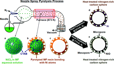
Melamine–formaldehyde (MF) resin was used as a source for the carbon and the nitrogen atoms of the spheres. After synthesizing MF resin from melamine and formaldehyde in NaOH aqueous solution, it was mixed with Ni precursors (10 at%) and CTAB (cetyl trimethylammonium bromide). The mixed solution was sprayed from a nozzle by N2 gas and then the droplets of the solution passed through the furnace (heating zone) while they were dried and pyrolyzed within the furnace (Scheme 1). The spherical products were collected on the filter and washed with ethanol and water to remove the residual of MF resin. The temperature of the furnace was varied to produce different types of spheres: the products are designated as 6N, 7N, and 8N, where the process temperatures of NSP are 673, 773, and, 873 K, respectively.
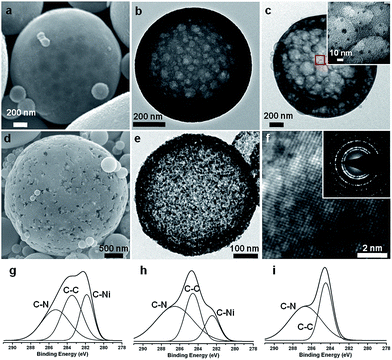
Hollow porous spheres are produced with the process temperature of 873 K. The spheres are polydispersed, having an average diameter of 1047 nm and a standard deviation of 829 nm (see ESI, Fig. S1a–h and S2 and Table S1†). Chemical cross-linking occurs within MF resins while the droplets pass through the furnace (Scheme 1a). Also, the functional groups incorporated in the MF resins such as –C–OH, –CNH2, and –CH can interact with Ni ions from the NiCl2 precursor to generate C–Ni bonds. Since the outside of a sphere is in a higher temperature region than its inside, the reaction occurs from the exterior, forming the shell part of the sphere (Scheme 1b). The shell thickness is dependent on the nickel content. TEM (Transmission Electron Microscopy) images of the spheres with various amounts of nickel show that the shell becomes thicker as the nickel content is increased; the shell of the products having 5 and 10 at% of nickel is much thinner than that having 30 at% (see ESI, Fig. S3a–d†). However, the nickel content does not affect the diameters of the spheres; the average diameters of the products having 5, 10, 15, and 30 at% of nickel are 1050, 1047, 1016, and 1036 nm, respectively. Since the drops of the solvent are vaporized and the remnant resin is decomposed at 873 K, the core is left out resulting in hollow spheres (Scheme 1c). As seen from the SEM (Fig. 1a) and TEM images (Fig. 1b) of 8N, the spheres produced with 10 at% of nickel at 873 K of the NSP process are hollow and have nanosize pores in the shell. The pores are generated during the pyrolysis process by decomposing the CTAB. Since the CTAB is in the aqueous solution, the CTAB forms spherical micelle structures while the core of the micelles consists of the carbon chain tail of CTAB and the cation head of CTAB is located on the shell of the micelles. The CTAB micelles were surrounded by the MF resins, and the micelles decomposed during the pyrolysis process, which resulted in the porous structures, However, this led the spheres to have a small BET (Brunauer–Emmett–Teller) surface area (6.81 m2 g−1). This indicates that most of the pores are embedded in the shell and have no windows to the outside of the spheres. Uniformly dispersed nickel atoms in nitrogen-rich carbon spheres could be discerned through the EDS (Energy Dispersive Spectrometer) elemental mapping (see ESI, Fig. S4a–e†). Carbon (Fig. S4b†), nitrogen (Fig. S4c†), oxygen (Fig. S4d†), and nickel (Fig. S4e†) atoms are distributed throughout the spheres, while the concentration of the atoms are higher on the rim because of their hollow structures. The existence of nickel in the spheres is also verified by XPS (X-ray photon spectroscopy); the elemental ratio of C![[thin space (1/6-em)]](https://www.rsc.org/images/entities/char_2009.gif) :
:![[thin space (1/6-em)]](https://www.rsc.org/images/entities/char_2009.gif) N
N![[thin space (1/6-em)]](https://www.rsc.org/images/entities/char_2009.gif) :
:![[thin space (1/6-em)]](https://www.rsc.org/images/entities/char_2009.gif) O
O![[thin space (1/6-em)]](https://www.rsc.org/images/entities/char_2009.gif) :
:![[thin space (1/6-em)]](https://www.rsc.org/images/entities/char_2009.gif) Ni for 8N is 62.21
Ni for 8N is 62.21![[thin space (1/6-em)]](https://www.rsc.org/images/entities/char_2009.gif) :
:![[thin space (1/6-em)]](https://www.rsc.org/images/entities/char_2009.gif) 25.95
25.95![[thin space (1/6-em)]](https://www.rsc.org/images/entities/char_2009.gif) :
:![[thin space (1/6-em)]](https://www.rsc.org/images/entities/char_2009.gif) 7.58
7.58![[thin space (1/6-em)]](https://www.rsc.org/images/entities/char_2009.gif) :
:![[thin space (1/6-em)]](https://www.rsc.org/images/entities/char_2009.gif) 2.66 (Fig. S5 and Table S2†). It is noted that although the amount of Ni is much lower than those of carbon and nitrogen, the peak intensity of C–Ni bonds is higher than that of C–C or C–N bonds (Fig. 1g). In this respect, it seems that nickel atoms are dispersed at the atomic scale and surrounded by several carbon atoms. In addition, no peak is observed in XRD (X-ray Diffraction) curves of 8N, which implies that the spheres have no crystalline structure. The heat treatment of 8N under the flow of H2 gas at 673 K was followed after washing and drying (Scheme 1d). The heat-treated 8N is designated as 8NH1. Although the spherical shape of 8NH1 was preserved, the average size was reduced by almost 40% (see ESI, Fig. S1i and j and Table S1†). Also, it is noted that nanosized (<10 nm) nickel particles are generated on the shell of 8NH1 after the heat treatment (Fig. 1c and see ESI, Fig. S6a†). It seems that nickel atoms in 8N are segregated from nitrogen-rich carbon spheres, forming nanosized nickel clusters. This is consistent with the XPS data20–26 of 8NH1, where the peak intensity of C–Ni bonds is lower than that of C–C bonds (Fig. 1h). Since nickel atoms constitute nanoparticles, the chances for nickel atoms to bond with carbon atoms are less than that of 8N. In addition, the heat treatment of 8N under N2 gas flow at 773 K was found to produce mesopores and micropores inside the shell, designated as 8NH2 (Scheme 1e). A slow heating rate of 1 K min−1 was used to preserve the porous structures during the step. The SEM images of 8NH2 show pores on the surface of the spheres (Fig. 1d). During the heat treatment step, nickel atoms were found to be segregated from nitrogen-rich carbon structures. This resulted in nickel oxide particles, which are clearly shown in the TEM images of 8NH2 (Fig. 1e and f). The oxygen atoms of NiO particles in 8NH2 are considered to be attributed from the NaOH solution and the formaldehyde parts of MF resin. The SAED (Selected Area Electron Diffraction) pattern of 8NH2 suggests that NiO particles have crystalline structures (Inset of Fig. 1f). The XRD curve of 8NH2 confirms that the particles are in the nickel oxide phase (see ESI, Fig. S6b†). The diffraction peaks at around 37°, 43°, and 63° can be indexed to (101), (012), and (110) of trigonal NiO, respectively.27–29 The C 1s XPS curve of 8NH2 has no C–Ni bond, but both the C–C and C–N bonds remain, which indicates that Ni atoms are completely detached from nitrogen-rich carbon structures and constitute nickel oxide particles (Fig. 1i). Also, the N 1s XPS spectrum of 8NH2 (Fig. S6c†), where the signals at 398.7 eV correspond to the sp2 hybridized nitrogen in triazine rings, supports that the nitrogen atoms do not bind with Ni. Although the melamine was used as a precursor for synthesis of the carbon spheres, it was found that the carbon spheres have different atomic structures from graphitic carbon nitride. In XPS spectra of the g–C3N4, there are two major C peaks around 288 (C
2.66 (Fig. S5 and Table S2†). It is noted that although the amount of Ni is much lower than those of carbon and nitrogen, the peak intensity of C–Ni bonds is higher than that of C–C or C–N bonds (Fig. 1g). In this respect, it seems that nickel atoms are dispersed at the atomic scale and surrounded by several carbon atoms. In addition, no peak is observed in XRD (X-ray Diffraction) curves of 8N, which implies that the spheres have no crystalline structure. The heat treatment of 8N under the flow of H2 gas at 673 K was followed after washing and drying (Scheme 1d). The heat-treated 8N is designated as 8NH1. Although the spherical shape of 8NH1 was preserved, the average size was reduced by almost 40% (see ESI, Fig. S1i and j and Table S1†). Also, it is noted that nanosized (<10 nm) nickel particles are generated on the shell of 8NH1 after the heat treatment (Fig. 1c and see ESI, Fig. S6a†). It seems that nickel atoms in 8N are segregated from nitrogen-rich carbon spheres, forming nanosized nickel clusters. This is consistent with the XPS data20–26 of 8NH1, where the peak intensity of C–Ni bonds is lower than that of C–C bonds (Fig. 1h). Since nickel atoms constitute nanoparticles, the chances for nickel atoms to bond with carbon atoms are less than that of 8N. In addition, the heat treatment of 8N under N2 gas flow at 773 K was found to produce mesopores and micropores inside the shell, designated as 8NH2 (Scheme 1e). A slow heating rate of 1 K min−1 was used to preserve the porous structures during the step. The SEM images of 8NH2 show pores on the surface of the spheres (Fig. 1d). During the heat treatment step, nickel atoms were found to be segregated from nitrogen-rich carbon structures. This resulted in nickel oxide particles, which are clearly shown in the TEM images of 8NH2 (Fig. 1e and f). The oxygen atoms of NiO particles in 8NH2 are considered to be attributed from the NaOH solution and the formaldehyde parts of MF resin. The SAED (Selected Area Electron Diffraction) pattern of 8NH2 suggests that NiO particles have crystalline structures (Inset of Fig. 1f). The XRD curve of 8NH2 confirms that the particles are in the nickel oxide phase (see ESI, Fig. S6b†). The diffraction peaks at around 37°, 43°, and 63° can be indexed to (101), (012), and (110) of trigonal NiO, respectively.27–29 The C 1s XPS curve of 8NH2 has no C–Ni bond, but both the C–C and C–N bonds remain, which indicates that Ni atoms are completely detached from nitrogen-rich carbon structures and constitute nickel oxide particles (Fig. 1i). Also, the N 1s XPS spectrum of 8NH2 (Fig. S6c†), where the signals at 398.7 eV correspond to the sp2 hybridized nitrogen in triazine rings, supports that the nitrogen atoms do not bind with Ni. Although the melamine was used as a precursor for synthesis of the carbon spheres, it was found that the carbon spheres have different atomic structures from graphitic carbon nitride. In XPS spectra of the g–C3N4, there are two major C peaks around 288 (C![[double bond, length as m-dash]](https://www.rsc.org/images/entities/char_e001.gif) N) and 284 eV (graphitic carbon).30 However, the carbon spheres have only one major peak around 284 eV (Fig. 1(g)–(i)). Also, carbon spheres have no peaks around 1571 and 1630 cm−1 (see Fig. S7† for more details) corresponding to C
N) and 284 eV (graphitic carbon).30 However, the carbon spheres have only one major peak around 284 eV (Fig. 1(g)–(i)). Also, carbon spheres have no peaks around 1571 and 1630 cm−1 (see Fig. S7† for more details) corresponding to C![[double bond, length as m-dash]](https://www.rsc.org/images/entities/char_e001.gif) N stretching modes30 for C3N4.
N stretching modes30 for C3N4.
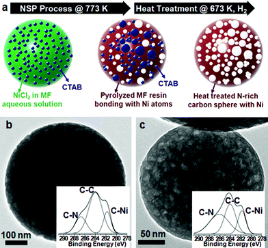
The porosity and atomic structures of nickel nitrogen-rich carbon spheres can be also controlled by the process temperature of the NSP method (Fig. 2a). The spheres produced at the NSP process temperature of 773 K, denoted as 7N (Fig. 2a and b and S9a and b†) and 673 K, denoted as 6N (ESI, Fig. S8a and b and S9e and f†), are solids, unlike the hollow structure of 8N (Scheme 1c and Fig. 1a and b). Because of the relatively low process temperature, only a small portion of surfactants is decomposed during the process and most of them remain with the spheres. XPS data show that 7N has a higher peak intensity of C–C bonds than those of C–Ni bonds and C–N bonds, while the 8N has a relatively similar peak intensity between C–C and C–Ni bonds (inset of Fig. 2b). Most C–C bonds detected by XPS data of 7N are from CTAB, whereas the peak of C–N bonds results from melamine. After the heat treatment of 7N under H2 at 673 K, more CTAB is decomposed, which generates pores inside the spheres, called 7NH (Fig. 2a and c). Since the CTAB is decomposed in 7NH, the XPS curve of 7NH has lower peak intensity of the C–C bond than that of 7N (Inset of Fig. 2c). Also, the average diameter of 7N is decreased by approximately by 20% after the heat treatment (see ESI, Fig. S9a–d and Table S1†). In addition, 6NH, which is produced by the heat treatment of 6N under H2 at 673 K, shows a similar shape of the structure to that of 7NH (Fig. S8c and S9g and h†).
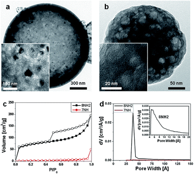
The hierarchical structures identified via TEM analysis of 8NH2 (Fig. 3a) with 7NH (Fig. 3b) show a significant difference in the specific surface area between 8NH2 and 7NH. The BET surface area for 8NH2 is 249.4 m2 g−1, which is about 30 times larger than that of 7NH (8.13 m2 g−1). For 7NH, its surface area is found to be extremely smaller than those of other porous structures in previous reports.31–34 During the heat treatment process, the internal porous structures may have expanded and effectively closed up certain vacancies rending 7NH's micropores and mesopores inaccessible. Comparing the high magnification TEM images, metal or metal oxide components have not been detected in 7NH unlike 8NH2. We therefore consider that there is little opportunity for 7NH to react with oxygen, thus being incapable of creating nickel oxide particles. Moreover, the isotherm curve of 8NH2 shows a notable hysteresis during adsorption and desorption of gas. This implies that there is a large pore volume (Fig. 3c). The pore volume of 8NH2 is 0.266 cm3 g−1, which is much larger than the 0.018 cm3 g−1 for 7NH. In addition, we find that 8NH2 has pores with ∼37.6 Å in diameter while there are no corresponding pores in 7NH (Fig. 3d). Also, 8NH2 has micropores with the average diameter of 7.5 Å. The pore size distribution of the micropores was obtained using the HK (Horvath–Kawazoe) method (inset of Fig. 3d).
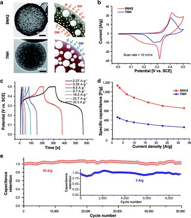
The activity of surface reactions can be determined by structural characteristics of materials. Both the porous and hollow structures could improve the properties of surface redox reactions for pseudo-capacitors by facilitating the accessibility of redox ions. The nickel oxide sites from both inside and outside of the hollow porous 8NH2 can be accessed by hydroxide ions, whereas the closed window of the pore for 7NH can offer the sites for electrochemisorption in the outside surface, as schematically demonstrated in Fig. 4a. We have performed electrochemical experiments to explore surface faradaic reactions for the electrode fabricated by the materials developed in this work (see the Experimental section). Fig. 4b shows the cyclic voltammetry (CV) data at a scan rate of 10 mV s−1, which was performed in the 1 M KOH aqueous electrolyte for the electrodes fabricated on 8NH2 and 7NH. Also, the CV data of 8NH2 and 7NH performed at different scan rates are shown in ESI Fig. S10 and S11,† respectively. As proposed in Fig. 4a, owing to many open pores and hollow structures, Fig. 4b supports that the intensities of redox reaction peaks for 8NH2 are dramatically higher than those of 7NH. The charge storage on NiO occurs via the reaction of NiO + OH− → NiOOH + e−. This reaction is associated with the pseudo-capacitive behavior in Fig. 4b and c that show corresponding Faradaic oxidation and reduction peaks in the CV and matching plateaus in the gravimetric charge/discharge curve, which is consistent with previous reports.35,36 Also, the intensities of cathodic and anodic peaks are increased in 8NH2 without significantly shifting their positions or introducing undesirable side reactions.
Fig. 4c also shows the charge/discharge profiles of 8NH2 at different current densities. In addition, the highest specific capacitance of 8NH2 is found to be 1130 F g−1, which is about 250% higher (459 F g−1) than that of 7NH (Fig. 4d). This is very high in consideration of the weight portion for NiO in 8NH2 (ESI, Fig. S12†). It is notable that the capacitance of NiO particles exceeds the capacitance of bare NiO particles. Several previous reports37–40 suggest that the composites with metal oxide and carbon nanomaterials generate the synergistic effect on capacitance. For example, the Ni–O–C bridges were found to give the excessive capacitance in the electrochemical devices.40 Furthermore, the capacitances of 8NH2 are well maintained for a high current density (660 F g−1 at 32.5 A g−1). In addition, there are previous reports41,42 for supercapacitors using high capacitance based on the NiO nanobelt41 and the NiO/Ni nanocomposite,42 which has been used as a part of the electrode. Also, our calculated capacitance, which is determined on the total mass of the electrode, shows the high efficiency in capacitance. Moreover, the structural advantage of our material also shows robust cycle life with excellent charge retention. We also studied the galvanostatic charge and discharge reactions by determining the specific capacitances at a high current density of 30 A g−1. The results show that the 8NH2 electrode preserves its capacitance over 50![[thin space (1/6-em)]](https://www.rsc.org/images/entities/char_2009.gif) 000 cycles with 100% capacitance retention (Fig. 4e). In addition, to evaluate the stability of the 8NH2 electrode at a low current density, we measured the cycle capability of the 8NH2 electrode at a current density of 3 A g−1 (Fig. 4e inset). These measurements support that the porous nitrogen-rich hollow spheres encapsulated with NiO particles preserve capacitance by utilizing their unique hierarchical structural characteristics. The nitrogen atoms,43 which are incorporated within 8NH2, promote the electrochemical reactions by coordinating with the available ions within the electrolyte. The micropores within the structure, in addition, enhance the hydrophilicity and electrolyte accessibility43 by channelling the redox ions of OH− to the NiO components. Finally, the hollow void44 within the structure services as an ion reservoir contributing to a potential ion-buffering effect. Consequently, these imply that multiple structural effects such as microporosity and hollow structure of 8NH2 can be applied to explain the exceptionally good charge retention at both high and low current densities.
000 cycles with 100% capacitance retention (Fig. 4e). In addition, to evaluate the stability of the 8NH2 electrode at a low current density, we measured the cycle capability of the 8NH2 electrode at a current density of 3 A g−1 (Fig. 4e inset). These measurements support that the porous nitrogen-rich hollow spheres encapsulated with NiO particles preserve capacitance by utilizing their unique hierarchical structural characteristics. The nitrogen atoms,43 which are incorporated within 8NH2, promote the electrochemical reactions by coordinating with the available ions within the electrolyte. The micropores within the structure, in addition, enhance the hydrophilicity and electrolyte accessibility43 by channelling the redox ions of OH− to the NiO components. Finally, the hollow void44 within the structure services as an ion reservoir contributing to a potential ion-buffering effect. Consequently, these imply that multiple structural effects such as microporosity and hollow structure of 8NH2 can be applied to explain the exceptionally good charge retention at both high and low current densities.
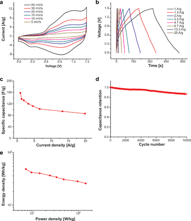
We have described the synthesis of 8NH2 – a NiO incorporated porous carbon hollow sphere – and showed experimental results that support structural factors contributing to the robust cycle life. In addition, to establish the applicability of the 8NH2 electrode to prepare a practical device, an asymmetric cell was assembled by combining with nitrogen-doped graphene as a negative electrode with 8NH2 as a positive electrode. The full cell configuration and the operating voltage were determined by performing the 3-electrode test for both nitrogen-doped graphene and 8NH2. The ultimate performance of the individual nitrogen-doped graphene electrode is shown in Fig. S13.† The mass of the active material on the anode and cathode was based on the mass ratio of 0.5, which was calculated from the capacitance at CV at 5 mV s−1 (see the Experimental section in the ESI†). The asymmetric devices are operated in a voltage window of 1.5 V at various CV scan rates (Fig. 5a). The stable gravimetric performances at various current densities of 1 to 20 A g−1 are shown in Fig. 5b and the specific capacitance was determined based on the total mass of both negative and positive electrodes (Fig. 5c). These results support that both the surface electrosorption of ions and the redox reaction of anions are well matched in this device. In addition, the well-matched configuration of the asymmetric cell shows the excellent cycle properties at a current density of 6.7 A g−1 as shown in Fig. 5d. A total capacitance loss of only 13.6% is detected after 10![[thin space (1/6-em)]](https://www.rsc.org/images/entities/char_2009.gif) 000 cycles. These results suggest that the high performance pseudocapacitive properties of the 8NH2 electrode could allow the high capacitance and stable properties in the full-cell configuration with other promising counter electrodes including nitrogen-doped graphene. Fig. 5e shows a Ragone plot of the asymmetric capacitor determined using the two-electrode full cell configuration and it shows the energy density from approximately 50 to 26 W h kg−1 at the power density from about 740 to 14
000 cycles. These results suggest that the high performance pseudocapacitive properties of the 8NH2 electrode could allow the high capacitance and stable properties in the full-cell configuration with other promising counter electrodes including nitrogen-doped graphene. Fig. 5e shows a Ragone plot of the asymmetric capacitor determined using the two-electrode full cell configuration and it shows the energy density from approximately 50 to 26 W h kg−1 at the power density from about 740 to 14![[thin space (1/6-em)]](https://www.rsc.org/images/entities/char_2009.gif) 522 W kg−1. These are excellent performance compared to those of other metal oxide structures such as nickel oxide based capacitors,45 nickel hydroxide based capacitors,46 and manganese oxide based asymmetric capacitor devices.47 Consequently, the experimental results in Fig. 5 demonstrate that the hollow 8NH2 can be utilized as a cathode electrode to realize high-performance metal oxide energy storage devices.
522 W kg−1. These are excellent performance compared to those of other metal oxide structures such as nickel oxide based capacitors,45 nickel hydroxide based capacitors,46 and manganese oxide based asymmetric capacitor devices.47 Consequently, the experimental results in Fig. 5 demonstrate that the hollow 8NH2 can be utilized as a cathode electrode to realize high-performance metal oxide energy storage devices.
Conclusions
In summary, we have developed a hard template-free synthesis of nickel oxide encapsulated hollow porous nitrogen-rich carbon spheres with multiporosity for high-performance pseudocapacitors having extremely robust cycles, where the pores inside the shell result from the removal of surfactants during the nozzle spray pyrolysis process without any hard templates while the thickness of the shell has been controlled by the amount of nickel atoms. In addition, the heat treatment of spheres generates micropores in the shell of spheres, thus leading to the higher surface area by about 30 times to store redox ions than that of the as-synthesized spheres. Moreover, it resulted in the mesopores capable of enhancing the diffusivity of redox ions. Indeed, these were found to enhance the accessibility of redox ions to nickel metal sites for surface Faradaic reactions, thus giving an ∼250% enhancement in capacitance, in addition to 100% capacitance retention over 50![[thin space (1/6-em)]](https://www.rsc.org/images/entities/char_2009.gif) 000 cycles at a high current density. Moreover, we provided experimental evidence that assembling the capsulated nickel oxide into a full asymmetric capacitor can be employed as practical positive electrodes in an asymmetric full cell with excellent performance in terms of both energy and power densities with robust cycle life.
000 cycles at a high current density. Moreover, we provided experimental evidence that assembling the capsulated nickel oxide into a full asymmetric capacitor can be employed as practical positive electrodes in an asymmetric full cell with excellent performance in terms of both energy and power densities with robust cycle life.
Acknowledgements
S. Y. Kim, H. M. Jeong, and J. H. Kwon contributed equally to this work. This research was supported by the Global Frontier R&D Program (2013M3A6B1078865) on Center for Hybrid Interface Materials (HIM) funded by the Ministry of Science, ICT & Future Planning, and the National Research Foundation of Korea (2011-0028737, 2012M1A2A2671813) and its BK21PLUS program. In addition, W. H. Suh thanks the Otis Williams Postdoctoral Fellowship.Notes and references
- A. M. Cao, J. S. Hu, H. P. Liang and L. J. Wan, Angew. Chem., Int. Ed., 2005, 44, 4391 CrossRef CAS PubMed.
- Y. F. Zhu, J. L. Shi, W. H. Shen, X. P. Dong, J. W. Feng, M. L. Ruan and Y. S. Li, Angew. Chem., Int. Ed., 2005, 44, 5083 CrossRef CAS PubMed.
- S. Ikeda, S. Ishino, T. Harada, N. Okamoto, T. Sakata, H. Mori, S. Kuwabata, T. Torimoto and M. Matsumura, Angew. Chem., Int. Ed., 2006, 45, 7063 CrossRef CAS PubMed.
- T. Harada, S. Ikeda, Y. H. Ng, T. Sakata, H. Mori, T. Torimoto and M. Matsumura, Adv. Funct. Mater., 2008, 18, 2190 CrossRef CAS.
- J. M. Shin, R. M. Anisur, M. K. Ko, G. H. Im, J. H. Lee and I. S. Lee, Angew. Chem., Int. Ed., 2009, 48, 321 CrossRef CAS PubMed.
- C. Almeida and A. J. G. Zarbin, Carbon, 2006, 44, 2869 CrossRef PubMed.
- S. Ikeda, K. Tachi, Y. H. Ng, Y. Ikoma, T. Sakata, H. Mori, T. Harada and M. Matsumura, Chem. Mater., 2007, 19, 4335 CrossRef CAS.
- A. B. Fuertes, T. Valdes-Solis, M. Sevilla and P. Tartaj, J. Phys. Chem. C, 2008, 112, 3648 CAS.
- R. M. Garcia, Y. J. Song, R. M. Dorin, H. R. Wang, P. Li, Y. Qiu, F. van Swol and J. A. Shelnutt, Chem. Commun., 2008, 2535 RSC.
- Y. C. Kang, H. S. Roh and S. B. Park, Adv. Mater., 2000, 12, 451 CrossRef CAS.
- R. M. Laine, J. Marchal, H. P. Sun and X. Q. Pan, Adv. Mater., 2005, 17, 830 CrossRef CAS.
- S. E. Skrabalak and K. S. Suslick, J. Am. Chem. Soc., 2005, 127, 9990 CrossRef CAS PubMed.
- W. H. Suh and K. S. Suslick, J. Am. Chem. Soc., 2005, 127, 12007 CrossRef CAS PubMed.
- R. M. Laine, J. C. Marchal, H. P. Sun and X. Q. Pan, Nat. Mater., 2006, 5, 710 CrossRef CAS PubMed.
- W. H. Suh, A. R. Jang, Y. H. Suh and K. S. Suslick, Adv. Mater., 1832, 2006, 18 Search PubMed.
- P. Simon and Y. Gogotsi, Nat. Mater., 2008, 7, 845 CrossRef CAS PubMed.
- M. F. El-Kady, V. Strong, S. Dubin and R. B. Kaner, Science, 2012, 335, 1326 CrossRef CAS PubMed.
- Y. Zhu, S. Murali, M. D. Solller, K. J. Ganesh, W. Cai, P. J. Fereira, A. Pirkle, R. M. Wallace, K. A. Cychosz, M. Thommes, D. Su, E. A. Stach and R. S. Ruoff, Science, 2012, 332, 1537 CrossRef PubMed.
- T. Brezesinski, J. Wang, S. H. Tolbert and B. Dunn, Nat. Mater., 2010, 9, 146 CrossRef CAS PubMed.
- D. Marton, K. J. Boyd, A. H. Albayati, S. S. Todorov and J. W. Rabalais, Phys. Rev. Lett., 1994, 73, 118 CrossRef CAS.
- J. W. Jang, C. E. Lee, S. C. Lyu, T. J. Lee and C. J. Lee, Appl. Phys. Lett., 2004, 84, 2877 CrossRef CAS PubMed.
- C. Ronning, H. Feldermann, R. Merk, H. Hofsass, P. Reinke and J. U. Thiele, Phys. Rev. B: Condens. Matter Mater. Phys., 1998, 58, 2207 CrossRef CAS.
- M. Tabbal, P. Merel, S. Moisa, M. Chaker, A. Ricard and M. Moisan, Appl. Phys. Lett., 1996, 69, 1698 CrossRef CAS PubMed.
- Y. Goto, K. Taniguchi, T. Omata, S. Otsuka-Yao-Matsuo, N. Ohashi, S. Ueda, H. Yoshikawa, Y. Yamashita, H. Oohashi and K. Kobayashi, Chem. Mater., 2008, 20, 4156 CrossRef CAS.
- T. Ujvari, A. Toth, G. J. Kovacs, G. Safran, O. Geszti, G. Radnoczi and I. Bertoti, Surf. Interface Anal., 2004, 36, 760 CrossRef CAS.
- M. V. Landau, M. Herskowitz, R. Agnihotri and J. E. Kegerreis, Ind. Eng. Chem. Res., 2008, 47, 6904 CrossRef CAS.
- Y. Lin, T. Xie, B. C. Cheng, B. Y. Geng and L. D. Zhang, Chem. Phys. Lett., 2003, 380, 521 CrossRef CAS PubMed.
- M. Ghosh, K. Biswas, A. Sundaresan and C. N. R. Rao, J. Mater. Chem., 2006, 16, 106 RSC.
- T. Ahmad, K. V. Ramanujachary, S. E. Lofland and A. K. Ganguli, Solid State Sci., 2006, 8, 425 CrossRef CAS PubMed.
- M. Kim, S. Hwang and J. S. Yu, J. Mater. Chem., 2007, 17, 1656 RSC.
- P. X. Hou, H. Orikasa, T. Yamazaki, K. Matsuoka, A. Tomita, N. Setoyama, Y. Fukushima and T. Kyotani, Chem. Mater., 2005, 17, 5187 CrossRef CAS.
- A. Vinu, Adv. Funct. Mater., 2008, 18, 816 CrossRef CAS.
- A. Vinu, K. Ariga, T. Mori, T. Nakanishi, S. Hishita, D. Golberg and Y. Bando, Adv. Mater., 2005, 17, 1648 CrossRef CAS.
- Y. D. Xia and R. Mokaya, Adv. Mater., 2004, 16, 1553 CrossRef CAS.
- K. W. Nam, K. H. Kim, E. S. Lee, W. S. Y, X. Q. Yang and K. B. Kim, J. Power Sources, 2008, 182, 642 CrossRef CAS PubMed.
- J. W. Lee, T. Ahn, J. H. Kim, J. M. Ko and J. D. Kim, Electrochim. Acta, 2001, 56, 4849 CrossRef PubMed.
- Z.-S. Wu, G. Zhou, L.-C. Yin, W. Ren, F. Li and H.-M. Cheng, Nano Energy, 2012, 1, 107 CrossRef CAS PubMed.
- W. H. Shin, H. M. Jeong, B. G. Kim, J. K. Kang and J. W. Choi, Nano Lett., 2012, 12, 2283 CrossRef CAS PubMed.
- G. Zhou, D. W. Wang, L. C. Yin, N. Li, F. Li and H. M. Cheng, ACS Nano, 2012, 6, 3214 CrossRef CAS PubMed.
- R. Zhou, C. Meng, F. Zhu, Q. Li, C. Liu, S. Fan and K. Jiang, Nanotechnology, 2010, 21, 345701 CrossRef PubMed.
- B. Wang, J. S. Chem, Z. Wang, S. Madhavi and X. W. Lou, Adv. Energy Mater., 2012, 2, 1188 CrossRef CAS.
- Q. Lu, M. W. Lattanzi, Y. Chen, X. Kou, W. Li, X. Fan, K. M. Unruh, J. G. Chen and J. Q. Xiao, Angew. Chem., Int. Ed., 2011, 50, 6847 CrossRef CAS PubMed.
- N. P. Wickramaratne, J. Xu, M. Wang, L. Zhu, L. Dai and M. Jaroniec, Chem. Mater., 2014, 26, 2820 CrossRef CAS.
- J. Han, G. Xu, B. Ding, J. Pan, H. Dou and D. R. MacFarlane, J. Mater. Chem. A, 2014, 2, 5352 CAS.
- F. Luan, G. Wang, Y. Ling, X. Lu, H. Wang, Y. Tong, X.-X. Liu and Y. Li, Nanoscale, 2013, 5, 7984 RSC.
- H. B. Li, M. H. Yu, F. X. Wang, P. Liu, Y. Liang, J. Xiao, C. X. Wang, Y. X. Tong and G. W. Yang, Nat. Commun., 2013, 4, 1894 CrossRef CAS PubMed.
- Z.-S. Wu, W. Ren, D.-W. Wang, F. Li, B. Liu and H.-M. Cheng, ACS Nano, 2010, 4, 5835 CrossRef CAS PubMed.
Footnotes |
| † Electronic supplementary information (ESI) available: See DOI: 10.1039/c4ee02897j |
| ‡ These authors contributed equally to this work. |
| § Present address: Samsung Advanced Institute of Technology (SAIT), 130, Samsung-ro, Yeongtong-gu, Suwon-si, Gyeonggi-do, 443-803, Republic of Korea. |
| This journal is © The Royal Society of Chemistry 2015 |

