Nickel hydroxide–nickel nanohybrids indirectly from coordination microfibers for high-performance supercapacitor electrodes†
Junhong
Zhao
a,
Junzhi
He
a,
Mengjun
Sun
a,
Meijiao
Qu
a and
Huan
Pang
*ab
aCollege of Chemistry and Chemical Engineering, Anyang Normal University, Anyang, 455002, Henan, P. R. China
bState Key Laboratory of Coordination Chemistry, Nanjing University, Nanjing, 210093, Jiangsu, P. R. China. E-mail: huanpangchem@hotmail.com; Web: http://huanpangchem.wix.com/advanced-material
First published on 3rd December 2014
Abstract
Nickel nanowire foams are primarily synthesized by the calcination of dimethylglyoxime nickel microfibers in Ar gas. Moreover, mesoporous nickel hydroxide–nickel nanohybrids are successfully obtained via oxidation of Ni nanowire foams in an alkaline H2O2 aqueous solution. Due to the mesoporous structure of nickel hydroxide and the high conductivity of the central Ni metal, electrodes assembled with nickel hydroxide–nickel nanohybrids show a highly accessible surface-interface site and high conductivity, and are successfully applied as high-performance supercapacitor electrodes.
1. Introduction
Nowadays, more and more attention is being paid to various power source devices for clean and efficient energy storage, such as Li–ion batteries, supercapacitors, fuel cells and so on.1–5 In recent years, electrochemical capacitors have received much attention due to their higher power density and longer cycle life compared to the secondary batteries and higher energy density than conventional electrical double-layer capacitors.6–8 In particular, electrochemical capacitors based on hydrous ruthenium oxides exhibit a much higher specific capacitance than conventional carbon materials and better electrochemical stability than electronically conducting polymer materials.9,10 Nevertheless, the high cost of this noble metal material limits its commercialization. Hence, much effort has been aimed at searching for alternative inexpensive electrode materials with good capacitive characteristics, such as Ni-based materials,11–20 Co-based materials21–31 and Mn-based materials,32–39etc. They show high specific capacitance and energy density, which can be ascribed to Faradic redox reactions.However, the poor electrical conductivity of metal oxides leads to lower electron transport rates. In order to solve this issue, recently a lot of effort is being made to improve the electrical conductivity. Many strategies were tried and two were proven to be effective: (a) one is to incorporate directly electrochemically active materials into good conductive carbon materials (activated carbon,40 mesoporous carbon,41 carbon nanotubes,42,43 or graphene44). However, it always results in a decrease in the conductivity of the carbon materials when some functional groups are introduced onto the carbon materials for better bonding with the pseudocapacitor materials; (b) the other one is to construct a pseudocapacitor material-conductive matrix hybrid nanostructure.45–49 The matrix with a porous conductive network improves the electron transport rate leading to an enhanced supercapacitor performance. For instance, Chen et al.45 synthesized an MnO2–gold matrix hybrid structure for supercapacitors. Xiao et al.46 constructed monolithic NiO–Ni matrix composites for supercapacitors by mechanically compacting Ni powder to produce thin pellet disks, followed by a subsequent low-temperature annealing process.
Recently, Ni(OH)2/nickel foam (NF) composites have been prepared.50–52 A hydrothermal method is applied to deposit ultrathin primary nanowalls of Ni(OH)2 on NFs, and the composites show a capacitance higher than the theoretical value.50 Moreover, porous and 3D nanostructured Ni(OH)2 is electrodeposited on NFs to synthesize the composites.51 The Ni(OH)2/NF composites have also been prepared by chemical bath deposition.52 The spike-piece-structured Ni(OH)2 multilayer nanoplate arrays on nickel foams are directly synthesized by a facile hydrothermal method, which shows high-performance for energy storage.53 The Ni(OH)2 nanoflake array on Ni foam was fabricated as a binder-free electrode material for high performance supercapacitors.54 Although these important developments have been made, there are no reports available for the synthesis of Ni(OH)2 nanoflakes on Ni micro/nanofibers and the corresponding applications of supercapacitors.
Dimethylglyoxime (CH3(C![[double bond, length as m-dash]](https://www.rsc.org/images/entities/char_e001.gif) NOH)2CH3, DMG) is a common organic precipitant for Ni2+ in industry.55 Herein, the red precursor was easily synthesized by mixing dimethylglyoxime and Ni(OAc)2 in aqueous solution with vigorous stirring (see the Experimental methods section and Fig. S1†). X-ray diffraction (XRD) analysis and scanning electron microscopy (SEM) observation confirmed that the obtained product is Ni(DMG)2, which has a one-dimensional morphology, with an average diameter of ∼1000 nm (corresponding XRD pattern and SEM image are shown in Fig. S2 and S3†). Dimethylglyoxime can chelate with an Ni2+ ion to form a square planar configuration with Ni2+ in the centre. The central metal Ni2+ ion interacts strongly with the adjacent molecules and the square planes stack face-to-face, resulting in a one-dimensional columnar structure.56 This inherent columnar structure would lead to the formation of Ni(DMG)2 microfibers. More importantly, we have successfully synthesized porous Ni nanowire foams (denoted P1) by the calcination of Ni(DMG)2 microfibers in Ar gas. The obtained Ni nanowire foams are further oxidized in an alkaline H2O2 aqueous solution under hydrothermal conditions. Thus mesoporous nickel hydroxide–nickel (Ni(OH)2–Ni) nanohybrids (denoted P2) are successfully obtained. The mesoporous structure and high surface area of Ni(OH)2 offer many nanochannels for the electrolytes or ions, and the central Ni improves the conductivity of the as-prepared electrode. At a relatively low current density of 1.25 A g−1, the mesoporous Ni(OH)2–Ni nanohybrid electrode delivers a high capacitance of 1793 F g−1. Even when the current density is increased by 10 fold, namely to 12.5 A g−1, the values remain as high as 850 F g−1.
NOH)2CH3, DMG) is a common organic precipitant for Ni2+ in industry.55 Herein, the red precursor was easily synthesized by mixing dimethylglyoxime and Ni(OAc)2 in aqueous solution with vigorous stirring (see the Experimental methods section and Fig. S1†). X-ray diffraction (XRD) analysis and scanning electron microscopy (SEM) observation confirmed that the obtained product is Ni(DMG)2, which has a one-dimensional morphology, with an average diameter of ∼1000 nm (corresponding XRD pattern and SEM image are shown in Fig. S2 and S3†). Dimethylglyoxime can chelate with an Ni2+ ion to form a square planar configuration with Ni2+ in the centre. The central metal Ni2+ ion interacts strongly with the adjacent molecules and the square planes stack face-to-face, resulting in a one-dimensional columnar structure.56 This inherent columnar structure would lead to the formation of Ni(DMG)2 microfibers. More importantly, we have successfully synthesized porous Ni nanowire foams (denoted P1) by the calcination of Ni(DMG)2 microfibers in Ar gas. The obtained Ni nanowire foams are further oxidized in an alkaline H2O2 aqueous solution under hydrothermal conditions. Thus mesoporous nickel hydroxide–nickel (Ni(OH)2–Ni) nanohybrids (denoted P2) are successfully obtained. The mesoporous structure and high surface area of Ni(OH)2 offer many nanochannels for the electrolytes or ions, and the central Ni improves the conductivity of the as-prepared electrode. At a relatively low current density of 1.25 A g−1, the mesoporous Ni(OH)2–Ni nanohybrid electrode delivers a high capacitance of 1793 F g−1. Even when the current density is increased by 10 fold, namely to 12.5 A g−1, the values remain as high as 850 F g−1.
2. Experimental methods
2.1 Materials preparation
2.2 Characterization
The morphology of the as-prepared samples was observed using a JEOL-6701F field-emission scanning electron microscope (FESEM) at an acceleration voltage of 5.0 kV. The phase analyses of the samples were performed by X-ray diffraction (XRD) on a Rigaku-Ultima III with Cu Kα radiation (λ = 1.5418 Å). Nitrogen adsorption–desorption measurements were performed using a Gemini VII 2390 Analyzer at 77 K using the volumetric method. The specific surface area was obtained from the N2 adsorption–desorption isotherms and was calculated by the Brunauer–Emmett–Teller (BET) method. Transmission electron microscopy (TEM) images and HRTEM, STEM images were captured on the FEI Tecnai G2 F20 S-TWIN instrument microscope at an acceleration voltage of 200 kV.2.3 Electrochemical measurements
An electrochemical study on mesoporous Ni(OH)2–Ni nanohybrid electrodes was carried out on a CHI 660D electrochemical work station (Shanghai Chenhua Instrument, Inc.). All electrochemical performances were carried out in a conventional three-electrode system equipped with a platinum electrode and a saturated calomel electrode (SCE) as the counter and reference electrodes, respectively. Before electrochemical measurements, O2 was purged out from the solution by the inert gas–Ar. The working electrode was made from first mixing the active materials, acetylene black and PTFE (polytetrafluoroethylene) in a weight ratio of 80![[thin space (1/6-em)]](https://www.rsc.org/images/entities/char_2009.gif) :
:![[thin space (1/6-em)]](https://www.rsc.org/images/entities/char_2009.gif) 15
15![[thin space (1/6-em)]](https://www.rsc.org/images/entities/char_2009.gif) :
:![[thin space (1/6-em)]](https://www.rsc.org/images/entities/char_2009.gif) 5, then coating it on a piece of foamed nickel of about 1 cm2, and pressing it into a thin foil at a pressure of 5.0 MPa. The weight of the active sample was about 5 mg. The electrolyte was a 3 M KOH solution. The capacitive properties of electrodes were determined by cyclic voltammetry and galvanostatic charge–discharge techniques. Electrochemical impedance spectroscopy measurements of all the samples were conducted at different biased potentials in the frequency range of 100 kHz to 0.01 Hz with an AC voltage amplitude of 5 mV by using PARSTAT2273.
5, then coating it on a piece of foamed nickel of about 1 cm2, and pressing it into a thin foil at a pressure of 5.0 MPa. The weight of the active sample was about 5 mg. The electrolyte was a 3 M KOH solution. The capacitive properties of electrodes were determined by cyclic voltammetry and galvanostatic charge–discharge techniques. Electrochemical impedance spectroscopy measurements of all the samples were conducted at different biased potentials in the frequency range of 100 kHz to 0.01 Hz with an AC voltage amplitude of 5 mV by using PARSTAT2273.
3. Results and discussion
Fig. 1 presents a schematic illustration of the formation of various Ni nanofoams composed of nanowires and mesoporous Ni(OH)2–Ni nanohybrids from Ni(DMG)2 microfiber precursors. After the Ni(DMG)2 microfiber precursor was calcined at 500 °C under Ar, porous Ni nanowire foams (denoted P1) were obtained. In Fig. 2, the XRD analysis confirms that the Ni(DMG)2 microfiber precursor has been completely transformed into pure Ni (JCPDS-040850). The XRD peaks are broad, indicating that the Ni nanocrystallites are in the nanometer range. Ni(OH)2–Ni nanohybrids (denoted P2) can be obtained by treating the Ni nanowire foams in an alkaline H2O2 solution under hydrothermal conditions. Corresponding XRD patterns are shown in Fig. 2, it is seen that the # mark is indexed to Ni(OH)2 (JCPDS-140117). However, the strongest peak is indexed to pure Ni (JCPDS-040850) due to the presence of a central Ni.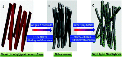 | ||
| Fig. 1 A schematic illustration of the formation of various Ni nanofoams composed of nanowires, and mesoporous Ni(OH)2–Ni nanohybrids. | ||
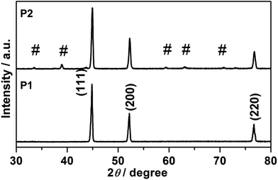 | ||
| Fig. 2 XRD patterns of P1, Ni nanowire foams; and P2, mesoporous Ni(OH)2–Ni nanohybrids, and the # sign is indexed to Ni(OH)2 (JCPDS-140117). | ||
FESEM images of the as-prepared samples are shown in Fig. 3. In Fig. 3a, the one-dimensional morphology has been maintained, and some Ni nanowires have intertwined with each other. Unlike the Ni(DMG)2 microfiber precursor, the diameter of Ni nanowires is ∼350 nm as shown in Fig. 3b, which is narrower than that of the Ni(DMG)2 microfiber. The surface of Ni nanowires appears smooth in the high magnification FESEM image (Fig. 3c). In Fig. 3d, it is clear that P2 has a one-dimensional morphology. A few nanowires assemble into big bundles. More importantly, there are many nanoplates on the surface of the one-dimensional structure. The diameter of a single Ni(OH)2–Ni nanohybrid is ∼500 nm, which is wider than the Ni nanowire due to the formation of Ni(OH)2 nanoplates (Fig. 3e). Some Ni(OH)2–Ni nanohybrids have a tube-like morphology as shown in Fig. 3f. From Fig. 3g, the size of a single nanoplate is determined to be ∼60 nm.
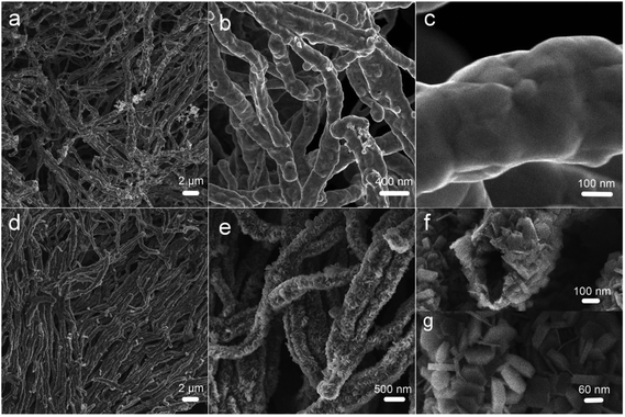 | ||
| Fig. 3 FESEM images of (a–c) P1, Ni nanowire foams; and (d–g) P2, mesoporous Ni(OH)2–Ni nanohybrids. | ||
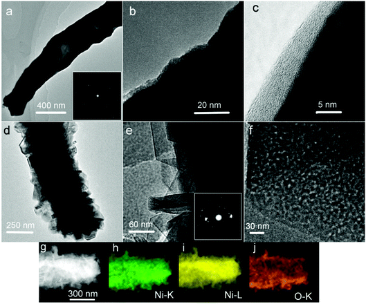
To better illustrate the structure and porosity, representative TEM images taken from the as-prepared samples are given in Fig. 4. In Fig. 4a, the Ni nanowire shows a hollow or semi-hollow structure and its corresponding SAED pattern is shown in the inset of Fig. 4a. The end of a single Ni nanowire is further magnified in Fig. 4b. It is clear that the Ni nanowire has good crystallinity, and thus possesses good electron transfer ability because a nearly perfect crystal shows little inner resistance. In the higher magnification image (Fig. 4c), there is an amorphous layer on the fringe of the Ni nanowire. The TEM result shows that there are many Ni(OH)2 nanoplates formed on the Ni nanowire foams (Fig. 4d) after hydrothermal treatment in an alkaline H2O2 solution. The Ni(OH)2 nanoplate is polycrystalline in nature, which is further proved by its corresponding SAED as shown in the inset of Fig. 4e. More importantly, at higher magnification, a lot of nanopores were observed on the nanoplates (Fig. 4f). It is well known that mesopores play a critical role in electrochemical processes, due to their capability of facilitating mass diffusion/transport (e.g., electrolyte penetration and ion transport) and ensuring a high electroactive surface area. To illustrate the spatial distribution of Ni(OH)2 and Ni in the composite, elemental mapping was performed on a representative Ni(OH)2–Ni nanohybrid (Fig. 4g) using TEM. The elemental mapping results (Fig. 4h–j) demonstrate the generally uniform distribution of O and Ni within the nanohybrid.
To gain further insight into the specific surface area of the as-prepared sample, Brunauer–Emmett–Teller (BET) measurements were performed. The N2 adsorption–desorption isotherms of P1 and P2 are shown in Fig. 5. The BET surface area for P1 and P2 are 89.8 m2 g−1 (P1) and 151.6 m2 g−1 (P2) respectively (Fig. 5). The pore-size distribution (in Fig. 5b) was determined by using the Barrett–Joyner–Halenda (BJH) method from the desorption branch of the isotherm. The average pore diameter of P1 is around 4.5 nm which may result from the intertwined hollow or semi-hollow structures and the amorphous fringe of P1, while that of P2 is around 3.2 nm which may result from the mesoporous morphology of Ni(OH)2 nanoplates. As is widely reported, an effective surface area usually offers many nanochannels for the electrolytes or ions to contact with the surface or the interfaces of nanoporous micro/nanostructures.
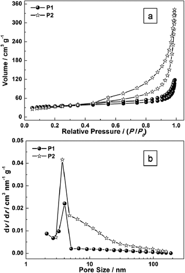 | ||
| Fig. 5 (a) N2 adsorption–desorption isotherms of as-prepared samples (P1 and P2); and (b) the pore-size distribution curves. | ||
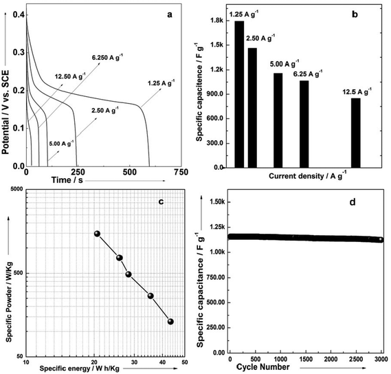
In order to determine the electrochemical capacitive properties of Ni(OH)2–Ni nanohybrids, cyclic voltammetry experiments within the 0.0–0.5 V range at a scan rate of 5 to 50 mV s−1 were performed on the mesoporous Ni(OH)2–Ni nanohybrid electrode in a 3.0 M KOH electrolyte at room temperature (Fig. S4†). The shape of the CV curves indicates the pseudocapacitive characteristics of the Ni(OH)2–Ni nanohybrid samples. Rate capability is one of the important factors for evaluating the power applications of supercapacitors. The discharge curves of the Ni(OH)2–Ni nanohybrid electrode at different current densities are shown in Fig. 6a. Discharge curves with an apparent plateau are consistent with the CV results. To calculate the specific capacitance during galvanostatic charge–discharge processes, the following equation is applied:30
 | (1) |
Fig. 6b gives the specific capacitance derived from galvanostatic discharge processes of the mesoporous Ni(OH)2–Ni nanohybrid electrode at different current densities. The mesoporous Ni(OH)2–Ni nanohybrid electrode generally exhibits a high specific capacitance and excellent rate capability. At a relatively low current density of 1.25 A g−1, the mesoporous Ni(OH)2–Ni nanohybrid electrode delivers a high capacitance of 1793 F g−1. Even when the current density is increased by 10 fold, namely 12.5 A g−1, the values remain as high as 850 F g−1.
In view of the high capacitance and excellent rate capability, we further calculated the energy and power densities, specific energy and specific power which are the two key factors for evaluating the power applications of electrochemical supercapacitors. A good electrochemical supercapacitor can provide high energy density and high specific capacitance. Specific energy (E) and specific power (P) derived from GV tests can be calculated from the following equations:30
 | (2) |
 | (3) |
Fig. 6c shows the plot of specific energy and specific power for the mesoporous Ni(OH)2–Ni nanohybrid electrode in a 3 M KOH aqueous solution. The specific energy of the mesoporous Ni(OH)2–Ni nanohybrid electrode decreases from 43.5 to 20.6 Wh kg−1, while the specific power increases from 131 to 1478 W kg−1. The good power density and energy density of mesoporous Ni(OH)2–Ni nanohybrid nanostructures make it a promising candidate for the electrode material of supercapacitors. The cyclic stability of the mesoporous Ni(OH)2–Ni nanohybrid electrode was further evaluated under galvanostatic charge–discharge conditions (Fig. 6d). It can be seen that only a very small capacitance drop is observed during the course of prolonged cycling. For example, the specific capacitance remains 98.4% of its initial value after 2000 cycles, and 97.2% after 3000 cycles, revealing its excellent cycling stability.
To identify the exact electrical conductivity of the electrode, we measured the electrochemical impedance spectra (EIS) for the mesoporous Ni(OH)2–Ni nanohybrid electrode in 3 M KOH at room temperature under different biased potentials in the frequency range 0.01–105 Hz as shown in Fig. 7. As seen in Fig. 7, the impedance plot at 0.40 V in 3 M KOH exhibits a line with a slope close to 70° along the imaginary axis (Z′′), and this is characteristic of an ideally polarizable electrode. At a potential of 0.6 or 0.8 V, the linear characteristic disappeared. Thus, the proper potential range, over which the electrode can generate desirable capacitance, is ≤0.40 V.
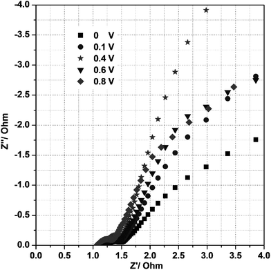 | ||
| Fig. 7 Electrochemical impedance spectra of the P2 electrode at different potentials under room temperature in a 3 M KOH solution. | ||
Such superior rate capability of the mesoporous Ni(OH)2–Ni nanohybrid electrode might be due to many reasons: the key one is to cause changes to the many paths of electrons, ions or electrolytes. For example, (1) the highly accessible surface area of mesoporous Ni(OH)2 structures; (2) the conductivity of the one-dimensional inner Ni nanostructures. Different surface–interface characteristics and conductivity might have different physicochemical adsorption–desorption abilities towards the ions and their diffusion paths, resulting in different electrochemical activities. It is worth mentioning that the abundant mesopores are of great significance for electrochemical processes.11,33,36,37 The highly mesoporous framework allows the facile penetration of the electrolyte that promotes the surface and near surface redox reactions, and guarantees a relatively high electroactive surface area. Thus high specific capacitance can be obtained even at high rates. This could also satisfactorily explain the superior performance of the mesoporous Ni(OH)2–Ni nanohybrid sample with abundant mesopores.
4. Conclusions
In summary, we demonstrate the facile synthesis of mesoporous Ni(OH)2–Ni nanohybrids with excellent supercapacitive performance. The Ni(DMG)2 microfiber is synthesized as the precursor via a rapid precipitation method at room temperature, followed by controlled annealing to obtain Ni nanowire foams. Moreover, mesoporous Ni(OH)2–Ni nanohybrids can be obtained by treating the Ni nanowire foams in an alkaline H2O2 solution under hydrothermal conditions. It was found that mesoporous Ni(OH)2–Ni nanohybrids possess more abundant mesopores and a higher BET surface area, and exhibit excellent supercapacitive performance in aqueous alkaline electrolytes. The remarkable electrochemical performance is likely due to the desirable nanohybrid and the unique mesoporous nanostructure. We also anticipate that the present synthetic strategy would be adopted to fabricate and optimize other promising nanohybrid materials for various applications.Acknowledgements
This work was supported by the Program for New Century Excellent Talents of the University in China (grant no. NCET-13-0645), the National Natural Science Foundation of China (NSFC-21201010, U1304504), the Program for Innovative Research Team (in Science and Technology) in University of Henan Province (14IRTSTHN004), the Science & Technology Foundation of Henan Province (122102210253, 13A150019), and the China Postdoctoral Science Foundation (2012M521115).Notes and references
- X. Peng, L. L. Peng, C. Z. Wu and Y. Xie, Chem. Soc. Rev., 2014, 43, 3303–3323 RSC.
- Y. G. Wang and Y. Y. Xia, Electrochim. Acta, 2006, 51, 3223–3227 CrossRef CAS.
- X. H. Wang, J. J. Ding, S. W. Yao, X. X. Wu, Q. Q. Feng, Z. H. Wang and B. Y. Geng, J. Mater. Chem. A, 2014, 2, 15958–15963 CAS.
- D. D. Zhu, Y. D. Wang, G. L. Yuan and H. Xia, Chem. Commun., 2014, 50, 2876–2878 RSC.
- S. Gu, R. Cai, T. Luo, Z. W. Chen, M. W. Sun, Y. Liu, G. H. He and Y. S. Yan, Angew. Chem., Int. Ed., 2009, 48, 6499–6502 CrossRef CAS PubMed.
- Q. F. Wang, X. F. Wang, J. Xu, X. Ouyang, X. J. Hou, D. Chen, R. M. Wang and G. Z. Shen, Nano Energy, 2014, 8, 44–51 CrossRef CAS.
- D. Zhou, X. R. Su, M. Boese, R. M. Wang and H. Z. Zhang, Nano Energy, 2014, 5, 52–59 CrossRef CAS.
- C. Zhang, H. Yin, M. Han, Z. Dai, H. Pang, Y. Zheng, Y. Q. Lan, J. Bao and J. Zhu, ACS Nano, 2014, 8, 3761–3770 CrossRef CAS PubMed.
- K. H. Chang, C. C. Hu and C. Y. Chou, Chem. Mater., 2007, 19, 2112–2119 CrossRef CAS.
- C. C. Hu, K. H. Chang, M. C. Lin and Y. T. Wu, Nano Lett., 2006, 6, 2690–2695 CrossRef CAS PubMed.
- C. Y. Cao, W. Guo, Z. M. Cui, W. G. Song and W. Cai, J. Mater. Chem., 2011, 21, 3204–3209 RSC.
- Z. Y. Lu, Z. Chang, J. F. Liu and X. M. Sun, Nano Res., 2011, 4, 658–665 CrossRef CAS.
- M. W. Xu, S. J. Bao and H. L. Li, J. Solid State Electrochem., 2007, 11, 372–377 CrossRef CAS.
- X. Sun, G. K. Wang, J. Y. Hwang and J. Lian, J. Mater. Chem., 2011, 21, 16581–16588 RSC.
- X. J. Zhang, W. H. Shi, J. X. Zhu, W. Y. Zhao, J. Ma, S. Mhaisalkar, T. L. Maria, Y. H. Yang, H. Zhang, H. H. Hng and Q. Y. Yan, Nano Res., 2010, 3, 643–652 CrossRef CAS.
- H. Jiang, T. Zhao, C. Z. Li and J. Ma, J. Mater. Chem., 2011, 21, 3818–3823 RSC.
- H. L. Wang, H. S. Casalongue, Y. Y. Liang and H. J. Dai, J. Am. Chem. Soc., 2010, 132, 7472–7477 CrossRef CAS PubMed.
- Y. Gao, J. H. Zhao, Z. Run, G. Zhang and H. Pang, Dalton Trans., 2014, 43, 17000–17005 RSC.
- S. B. Yang, X. L. Wu, C. L. Chen, H. L. Dong, W. P. Hu and X. K. Wang, Chem. Commun., 2012, 48, 2773–2275 RSC.
- H. Pang, Y. Ma, G. Li, J. Chen, J. Zhang, H. Zheng and W. Du, Dalton Trans., 2012, 41, 13284–13291 RSC.
- R. B. Rakhi, W. Chen, D. Cha and H. N. Alshareef, Nano Lett., 2012, 12, 2559–2567 CrossRef CAS PubMed.
- C. Z. Yuan, L. Yang, L. R. Hou, L. F. Shen, X. G. Zhang and X. W. Lou, Energy Environ. Sci., 2012, 5, 7883–7888 CAS.
- B. Wang, T. Zhu, H. B. Wu, R. Xu, J. S. Chen and X. W. Lou, Nanoscale, 2012, 4, 2145–2149 RSC.
- S. K. Meher and G. R. Rao, J. Phys. Chem. C, 2011, 115, 15646–15654 CAS.
- G. Q. Zhang and X. W. Lou, Sci. Rep., 2013, 3, 1470 Search PubMed.
- H. Jiang, J. Ma and C. Z. Li, Chem. Commun., 2012, 48, 4465–4467 RSC.
- H. L. Wang, Q. M. Gao and L. Jiang, Small, 2011, 7, 2454–2459 CAS.
- T. Y. Wei, C. H. Chen, H. C. Chien, S. Y. Lu and C. C. Hu, Adv. Mater., 2010, 22, 347–351 CrossRef CAS PubMed.
- H. B. Wu, H. Pang and X. W. Lou, Energy Environ. Sci., 2013, 6, 3619–3626 CAS.
- H. Pang, J. Deng, J. Du, S. Li, J. Li, Y. Ma, J. Zhang and J. Chen, Dalton Trans., 2012, 41, 10175–10181 RSC.
- C. Z. Yuan, J. Li, L. R. Hou, X. G. Zhang, L. F. Shen and X. W. Lou, Adv. Funct. Mater., 2012, 22, 4592–4597 CrossRef CAS.
- D. D. Zhu, Y. D. Wang, G. L. Yuan and H. Xia, Chem. Commun., 2014, 50, 2876–2878 RSC.
- M. J. Deng, P. J. Ho, C. Z. Song, S. A. Chen, J. F. Lee, J. M. Chen and K. T. Lu, Energy Environ. Sci., 2013, 6, 2178–2185 CAS.
- X. H. Tang, H. J. Li, Z. H. Liu, Z. Yang and Z. L. Wang, J. Power Sources, 2011, 196, 855–859 CrossRef CAS.
- L.-Q. Mai, F. Yang, Y.-L. Zhao, X. Xu, L. Xu and Y.-Z. Luo, Nat. Commun., 2011, 2, 318 CrossRef PubMed.
- Z. S. Wu, W. C. Ren, D. W. Wang, F. Li, B. L. Liu and H.-M. Cheng, ACS Nano, 2010, 4, 5835–5842 CrossRef CAS PubMed.
- Q. Li, Z. Wang, G. Li, R. Guo, L. Ding and Y. Tong, Nano Lett., 2012, 12, 3803–3807 CrossRef CAS PubMed.
- W. F. Wei, X. W. Cui, W. X. Chen and D. G. Ivey, Chem. Soc. Rev., 2011, 40, 1697–1721 RSC.
- H. Pang, S. M. Wang, G. C. Li, Y. H. Ma, J. Li, X. X. Li, L. Zhang, J. S. Zhang and H. H. Zheng, J. Mater. Chem. A, 2013, 1, 5053–5060 CAS.
- J. R. Zhang, D. C. Jiang, B. Chen, J. J. Zhu, L. P. Jiang and H. Q. Fang, J. Electrochem. Soc., 2001, 148, 1362–1367 CrossRef.
- Y. F. Yan, Q. L. Cheng, G. C. Wang and C. Z. Li, J. Power Sources, 2011, 196, 7835–7840 CrossRef CAS.
- J. Ren, L. Li, C. Chen, X. L. Chen, Z. B. Cai, L. B. Qiu, Y. G. Wang, X. G. Zhu and H. S. Peng, Adv. Mater., 2013, 25, 1155–1159 CrossRef CAS PubMed.
- S. W. Lee, J. Kim, S. Chen, P. T. Hammond and Y. Shao-Horn, ACS Nano, 2010, 4, 3889–3896 CrossRef CAS PubMed.
- Y. Zhao, C. G. Hu, Y. Hu, H. H. Cheng, G. Q. Shi and L. T. Qu, Angew. Chem., Int. Ed., 2012, 124, 11533–11537 CrossRef.
- X. Y. Lang, A. Hirata, T. Fujita and M. W. Chen, Nat. Nanotechnol., 2011, 6, 232–236 CrossRef CAS PubMed.
- Q. Lu, M. W. Lattanzi, Y. P. Chen, X. M. Kou, W. F. Li, X. Fan, K. M. Unruh, J. G. Chen and J. Q. Xiao, Angew. Chem., Int. Ed., 2011, 50, 1–5 CrossRef.
- G. X. Pan, X. Xia, F. Cao, P. S. Tang and H. F. Chen, Electrochim. Acta, 2012, 63, 335–340 CrossRef CAS.
- M. Hasan, M. Jamal and K. M. Razeeb, Electrochim. Acta, 2012, 60, 193–200 CrossRef CAS.
- M. Salari, S. H. Aboutalebi, K. Konstantinov and H. K. Liu, Phys. Chem. Chem. Phys., 2011, 13, 5038–5041 RSC.
- Z. Lu, Z. Chang, W. Zhu and X. M. Sun, Chem. Commun., 2011, 47, 9651–9653 RSC.
- G. W. Yang, C. L. Xu and H. L. Li, Chem. Commun., 2008, 6537–6539 RSC.
- U. M. Patil, K. V. Gurav, V. J. Fulari, C. D. Lokhande and O. S. Joo, J. Power Sources, 2009, 188, 338–342 CrossRef CAS.
- L. C. Wu, Y. J. Chen, M. L. Mao, Q. H. Li and M. Zhang, ACS Appl. Mater. Interfaces, 2014, 6, 5168–5174 CAS.
- B. L. Hua, X. Y. Qin, A. M. Asiri, K. A. Alamry, A. O. Al-Youbi and X. P. Sun, Electrochim. Acta, 2013, 107, 339–342 CrossRef.
- L. Tschugaeff, Ber. Dtsch. Chem. Ges., 1905, 38, 2520–2522 CrossRef.
- K. Yamamoto, T. Kamata, Y. Yoshida, K. Yase, F. Mizukami and T. Ohta, Adv. Mater., 1998, 10, 1018–1022 CrossRef CAS.
Footnote |
| † Electronic supplementary information (ESI) available. See DOI: 10.1039/c4qi00145a |
| This journal is © the Partner Organisations 2015 |

