Sodium potassium niobate (K0.5Na0.5NbO3, KNN) thick films by electrophoretic deposition
Morgane Dolhenab,
Amit Mahajana,
Rui Pinhoa,
M. Elisabete Costaa,
Gilles Trolliardb and
Paula M. Vilarinho*a
aDepartment of Materials and Ceramics Engineering, CICECO, University of Aveiro, 3810-193 Aveiro, Portugal. E-mail: paula.vilarinho@ua.pt
bScience of Ceramic Processing and Surface Treatments, University of Limoges, 87060 Limoges, France
First published on 10th December 2014
Abstract
K0.5Na0.5NbO3 (KNN) is one of the most promising lead free compositions to substitute lead based piezoelectrics. Due to size and functionality demands, thick films are currently required for specific electroceramics applications. However, what is lacking is the exploitation of low cost, solution-based processes for the fabrication of KNN thick films that are versatile and easy to scale up, such as electrophoretic deposition (EPD). In this article, KNN thick films with thicknesses ranging from 10–60 μm, prepared by EPD on platinum substrates, are reported. The films are made from acetone with triethanolamine suspension media. When sintered at 1100 °C/2 h they possess relative permittivity and dielectric loss of ∼393 and ∼0.07, respectively, at room temperature and at 1 MHz. KNN films show piezoelectric response (d33) of ~40 pC N−1. It is notable that such values are comparable to the properties of equivalent bulk ceramics. The study of the relationships between processing variables and the films' properties shows that, through a simple and yet low cost process such as EPD, thick KNN films can be consistently designed to be suited to the required application. These results suggest that this fabrication method is very promising as a core technology for low-cost and high-performance KNN thick films.
Introduction
Up to now, compositions within the solid solution between PbZrO3 and PbTiO3, generally designated as PZT (Pb1−xZrxTiO3), have been widely used in piezoelectric actuators, sensors and transducers, and more recently as promising energy harvesters. However, the use of PZT that contains more than 60 wt% of lead will soon be severely restricted, due to lead toxicity.1 Among the several possible lead free candidates to substitute PZT, three main systems have been considered: Ba0.5Na0.5TiO3–BaTiO3 (BNT–BT), (1 − x)[Ba0.92Zr0.08TiO3] − (x)[Ba0.92Ca0.08TiO3] (BZT–BCT), and sodium potassium niobate (K1−xNax)NbO3 (KNN). Much attention has been paid to KNN due to its high Curie temperature (Tc ∼ 420 °C), a piezoelectric d33 coefficient between 80 and 160 pC N−1 (for undoped KNN), and a high electromechanical coupling coefficient (kp) of 0.39.2 Moreover, in 2004 Saito et al.,3 and more recently (2014) Wang et al.,4 reported that doped and textured KNN ceramics with Tc < 400 °C have comparable properties to PZT.K1−xNaxNbO3 is a solid solution between KNbO3 and NaNbO3, and the highest dielectric and piezoelectric values were reported for x = 0.5(K0.5Na0.5NbO3).5–7 The crystallographic structure of KNN was first proposed by Shirane et al.8 as orthorhombic at room temperature, changing to tetragonal at 200 °C and then to cubic at 400 °C. However, the orthorhombic assignment is also consistent with a monoclinic structure with b > 90. Indeed, more recently using polarized Raman analysis performed on KNN single crystals, we were able to perform a precise Raman mode assignment for the monoclinic structure in KNN single crystals.9 K0.5Na0.5NbO3 has the following polymorphisms: a low temperature (<123 °C) rhombohedral phase, room temperature monoclinic (orthorhombic) phase, high temperature tetragonal (200–410 °C) phase and final cubic (>410 °C) phases.10,11
Besides the environmental issues, current trends in the microelectronics and related industries demand increased integration and functionality, small size, and reduced costs. Hence, thick films of dielectric materials are being considered to replace the dielectric components currently utilised in bulk ceramic form. Within this context, thick films of KNN are of industrial interest for various electronic applications in which miniaturised capacitors, sensors and actuators, among others are required. When compared with thin films, there are applications in which a bulk-type response is required, and for that thick films will be appropriate.
Thick films of KNN have been prepared by many different methodologies, such as spin-coating, tape-casting, hydrothermal methods and screen-printing. Wang et al.12 reported the fabrication of lead-free KNN by spin-coating – 3.5 μm thick films exhibited a high d33 of 61 pm V−1. KNN thick films fabricated by hydrothermal method at 240 °C have been reported by Shiraishi et al.,13,14 and 4 to 6 μm thick films have good ferroelectric and piezoelectric properties (d33 = 68 pm V−1). Lusiola et al. reported the fabrication of NaNbO3–K0.5Na0.5NbO3 (NN–KNN) thick films using a low temperature molten salt powder synthesis combined with a hybrid powder/sol gel ink film.15 These films have a piezoelectric coefficient and relative permittivity around 18 pC N−1 and 250 to 800 (depending on the poling conditions), respectively. However, with chemical solution deposition methods, a repeated number of depositions are required to achieve a thick layer, increasing drastically the amount of defects in the final film, besides being a lengthy and costly process.
Of all techniques for the fabrication of thick films, electrophoretic deposition (EPD) stands out due its high flexibility, low cost and simplicity of application.16,17 Moreover, EPD allows the fabrication of intricate shapes, and can be scaled-up for large volume fabrication. EPD has been exploited for the fabrication of different electroceramic thick films, such as PZT on alumina substrates,18 PZT on copper and platinum foils,19 BaNd2Ti5O14 (BNT) on platinum foils,20 TiTe3O8 on platinum and alumina substrates,21 and even for multilayering new high permittivity composites for high frequency applications (in this case BaLa4Ti4O15 (BLT) and BNT),22 among others. However, the preparation of KNN thick films by electrophoretic deposition was only reported once.23 Although that paper proves the feasibility of getting KNN thick films by EPD, processing studies, dielectric characterization and relations between processing conditions and properties have not been reported.
Within this context, in the present work K0.5Na0.5NbO3 (KNN) thick films are deposited on Pt foils by EPD and sintered at 1100 °C for 2 h. We investigate the key parameters, and establish the relationships between suspension media, EPD process conditions, microstructure of the deposits, and resulting electrical properties of KNN films. This work is also a part of a wide ranging study on the EPD processing of electroceramics that we have been carrying out. The use of EPD is well documented in the area of solid-state fuel cells and biomaterials.16 However, improved knowledge of EPD for dielectrics, piezoelectrics, ferroelectrics and related materials is still required. In our previous papers we have reported EPD of different electroceramic systems: piezoelectrics such as PZT, incipient ferroelectrics such as SrTiO3, low loss dielectrics such as BNT, and more recently low sintering temperature such as Tellurium based compounds.19–22 Among these results, we demonstrated that the selection of the medium, the stability of the suspensions, and the control of the particle zeta potentials, critical for a good deposition, need to be established for each new electroceramic material being processed by EPD. The current study on KNN thick films has not been reported before, and it is of interest for the fabrication of KNN thick films and exploitation of KNN assets for the electroceramics community.
Experimental
K0.5Na0.5NbO3 (KNN) powders were synthesised by a solid-state reaction method starting from Na2CO3 (Chempur, purity 99.5%), K2CO3 (Merck, purity 99.0%) and Nb2O5 (BDH Chemicals, purity 99.5%). Due to their hygroscopic nature, the carbonates Na2CO3 and K2CO3 were heated to 150 °C immediately prior to weighing. The powders were weighed according to the 1![[thin space (1/6-em)]](https://www.rsc.org/images/entities/char_2009.gif) :
:![[thin space (1/6-em)]](https://www.rsc.org/images/entities/char_2009.gif) 1
1![[thin space (1/6-em)]](https://www.rsc.org/images/entities/char_2009.gif) :
:![[thin space (1/6-em)]](https://www.rsc.org/images/entities/char_2009.gif) 2 stoichiometry, and ball milled in Teflon jars containing absolute ethanol as a media and zirconia balls. The ball milling was performed for 5 h at 200 rpm. After drying the stoichiometric powders in the oven at 150 °C for 24 h, they were calcined in air at 850 °C for 2 h, with a heating rate of 2 °C min−1. The calcined powders were ball milled (under identical conditions to the ones described above) to obtain fine particle size, which is essential for a stable suspension.
2 stoichiometry, and ball milled in Teflon jars containing absolute ethanol as a media and zirconia balls. The ball milling was performed for 5 h at 200 rpm. After drying the stoichiometric powders in the oven at 150 °C for 24 h, they were calcined in air at 850 °C for 2 h, with a heating rate of 2 °C min−1. The calcined powders were ball milled (under identical conditions to the ones described above) to obtain fine particle size, which is essential for a stable suspension.
EPD was conducted in an acetone medium (Carlo Erba, purity > 99%), and the final concentration of KNN particles in the suspension is 10 g L−1. Triethanolamine (TEA) and iodine (I2) (dissolved in acetone) were used as additives to modify both the pH of the suspension medium and the surface charge of the particles. Suspensions were prepared by ultrasonication for 1 h followed by magnetic stirring for 2 h. Platinum foils (11 × 11 × 0.025 mm, Good Fellow, U.K.) were used as substrates.
The zeta potential of the suspensions was measured by Zetasizer (Malvern Instruments, Zetasizer Nano ZS). The degree of dispersion of KNN powders in the suspension was evaluated by UV light transmittance using a UV spectrophotometer (UV-vis-NIR, UV-3100, SHIMADZU), and the particle size distribution in the different media was studied by Particle Size Analyzer (Coulter LS 230).
The deposition of thick films was carried out under dc electric field (EPS, Stromversorgung Gmbh, Germany). A homemade EPD cell with a working distance of 20 mm between the opposite platinum electrodes was used to fabricate the thick films. The deposition of the films was carried out at constant voltage and constant time mode. A digital multimeter (MY-64, MASTECH, Hong Kong) was attached in series to measure the electric current during the EPD process. For comparison purposes, some depositions were carried out in water as well. The deposited KNN films were dried at room temperature for at least 24 h to evaporate the solvent before sintering. Some of the films were iso-statically pressed at 200 MPa for 5 min in order to increase the green density of the films. Films were sintered in air at 1100 °C for 2 h with a heating of 2 °C min−1 in a box furnace and covered with KNN powders to minimize the alkaline volatilization. The surface morphology and the thickness of the films were evaluated by Scanning electron microscope (SEM, Hitachi, S-4100). X-ray diffraction (XRD, PANalytical X'Pert PRO) was used for the structural analysis of the films before and after sintering.
Electrical measurements were carried out using a metal–insulator–metal (MIM) configuration with Au as top electrodes, sputtered through a shadow mask of 1 mm diameter. Relative permittivity (εr) and loss tangent (tan![[thin space (1/6-em)]](https://www.rsc.org/images/entities/char_2009.gif) δ) were evaluated using an impedance bridge. εr and tan
δ) were evaluated using an impedance bridge. εr and tan![[thin space (1/6-em)]](https://www.rsc.org/images/entities/char_2009.gif) δ were measured at 1 MHz as a function of temperature, and at room temperature as a function of frequency.
δ were measured at 1 MHz as a function of temperature, and at room temperature as a function of frequency.
The piezoelectric coefficient d33 is an important parameter to be evaluated from the application point of view. Direct piezoelectric coefficient was measured by applying fixed force of 250 × 10−3 N using the Berlincourt method (Berlincourt meter, Si-nocera, YE 2730A) that operates at 110 Hz. These measurements were conducted on poled films. The poling was conducted using point plane corona setup. The voltage amplifier (Glassman high voltage, EQ020R060-22) was used to apply dc bias and the temperature was monitored by Eurotherm controller (3216). The poling was carried out by fixing the upper and bottom electrodes at 1.5 cm distance apart and KNN thick films were placed on the bottom electrode in-line with the top electrode. The films were poled at 80 °C (this is the maximum temperature attainable in the present setup) with applied voltage of 12 kV for 2 h. For d33 measurements top electrodes of Au were sputtered through a shadow mask of 1.5 mm diameter. The bottom electrode substrate (platinum) was used. The sample was clamped between the probes to measure the piezoelectric coefficient.
Results and discussion
The X-ray diffraction pattern of KNN powders is depicted in Fig. 1. KNN powders calcined at 850 °C for 2 h are single phase, and crystallize with a monoclinic (orthorhombic) structure (JCPDS 00-061-0315). As is characteristic of polycrystalline KNN, the most intense diffraction line corresponds to the crystallographic (110) plane.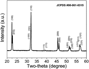 | ||
| Fig. 1 XRD pattern of the K0.5Na0.5NbO3 powders calcined at 850 °C for 2 h. Monophasic KNN powders were obtained. | ||
The quality of the EPD films mainly depends on two groups of parameters: those related to the suspension, such as powder particle size, dielectric constant and electrical conductivity of the liquid; and those related to the processing, including physical parameters such as deposition time and applied voltage.16,24 It is well known that the selection of the medium, the stability of the suspensions, and the control of the particle potentials are critical for a good deposition, but unfortunately there is no universal suspension medium for the EPD of oxides, and this needs to be established for each new material.22
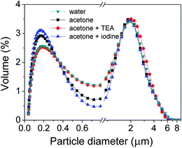
In ideal suspensions, the mobility of the particles due to electrophoresis must be higher than that due to gravity. Hence, charge, particle size and particle size distribution are important parameters to control and ensure a stable suspension. Fig. 2 depicts the particle size distribution of KNN powders in different media (water and acetone, with and without additives). The particle size of the milled KNN calcined powders is below 5 μm. All the suspensions of particles in media are characterized by a bimodal distribution, with the highest volume% of particles showing a peak centred around 2.2 μm, but with a similar fraction of small particles below 1 μm, with a lower peak around 0.2 μm. The water-based suspension exhibits the lowest volume% of sub-micron particles. However, this volume% is slightly increased to 2.9% in the acetone medium and to 3.2% for acetone with iodine (I2). For acetone with TEA, the particle size distribution is very similar to the behaviour in water. There are no significant variations in the particle distributions for fraction of particle sizes greater than 1 μm between all the suspensions.
Particle size is essential to guarantee a stable suspension in which particles do not settle, but the stability of the suspension is also highly affected by particle charge and media. Indeed, the medium acts as a vehicle to transport the particles in the suspension to the substrate. Critically, in EPD the suspension medium determines the magnitude of the charge that is developed on the particle surface in suspension, thus ensuring the stability of the suspension and, as a consequence, a successful deposition.
A variety of nonaqueous organic solvents are commonly used to prepare suspensions for EPD, such as acetone, ethanol, acetic acid and isopropanol, among others. Organic liquids are generally preferred in relation to water, due to their high density, good chemical stability and low conductivity. From our previous work,25 BNT thick films deposited from acetone with I2− based suspensions resulted in uniform, homogeneous and dense microstructure and good dielectric properties, in this study an acetone suspension medium was selected as well, and two different additives used: iodine (I2) and triethanolamine (TEA). As a reference, the stability of the suspensions was compared with the stability in water.
The stability of the studied KNN suspensions was assessed by UV transmittance spectroscopy and zeta potential measurements (Fig. 3 and 4). UV transmittance results illustrate that the transmittance is higher for water-based suspensions than for the acetone-based ones. The transmittance percentage varies between 17.7 and 25.6% for water, compared to 4 to 11% for acetone, which indicates a lower stability for the water based KNN suspensions. These high transmittance values for water can be explained by the fact that the particles settled in the very first seconds of stabilization. The lower degree of transmittance observed for KNN in acetone-based suspensions indicates a better dispersion of the particles in acetone, and a greater stability with the time. The transmittance percentage slightly increases with time for EPD carried out in acetone-based media, because of the sedimentation of the suspended particles over time. However, even after a long period of time (600 s), the transmittance percentage is relatively low, meaning that the suspensions are quite stable with time. A decrease in the transmittance percentage was observed after the addition of additives. In the case of water, the transmittance percentage decreases from ∼25.6% to 21.3% with the addition of TEA, and from 25.6% to 17.7% with the addition of I2. Identical behaviour was observed for acetone-based suspensions, for which the lowest transmittance occurred with I2 addition, the transmittance percentage decreasing from ∼8.7% to 6.4% with the addition of I2. For acetone with TEA, the transmittance percentage increases after 300 s, which may be due to the faster sedimentation of the larger particles, corroborating the results of particle size distribution. The UV transmittance study clear indicates the high stability of the suspensions with additives.
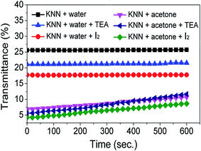 | ||
| Fig. 3 UV transmittance as a function of time for KNN suspensions in acetone and in water without and with additives. Acetone-based suspensions with additives are the most stable ones. | ||
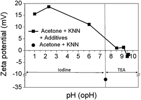
Though stable and well-dispersed, suspensions should produce densely packed deposits;26 the use of suspensions with high zeta potential and low ionic conductivity are also determinant aspects.27 The zeta potential is defined as the potential difference between the dispersion medium and the stationary layer of the fluid attached to the dispersed particle. It indicates the degree of repulsion between adjacent, similarly charged particles in dispersion, and is a measure of the stability of suspensions. Therefore, colloids with high zeta potential (negative or positive) are electrically stabilized, while colloids with low zeta potentials tend to coagulate or flocculate. A value of 25 mV (positive or negative) can be taken as the arbitrary value that separates low-charged surfaces from highly charged surfaces [ASTM Standard], but at the same time it is a measure of mobility of charged particles under an electric field. Therefore, zeta potential or electrophoretic mobility is commonly used to determine the ability of a suspension to be deposited by EPD.
The zeta potential curves of KNN particles in acetone-based suspensions as a function of the operational pH are illustrated in Fig. 4. I2 and TEA were used to modify the pH of the suspension. The zeta potential curves revealed that the KNN particles in acetone are positively charged below the isoelectric point at pH ≈ 9.3, and negatively charged above this point. The KNN suspension exhibits a positive zeta potential of 1.34 mV at pH of 9.16 for acetone with TEA. In the case of acetone with I2, the zeta potential was increased by adding I2 from 11.1 to 18.6 mV, corresponding to a decrease of the pH value from 6 to 2.3.
Iodine has been previously shown to be an effective additive to disperse PZT, BaxSr1−xTiO3 (BST) and BaNd2Ti5O14 (BNT)28,29 powders for EPD processes. It is reported that protons are formed by a reaction between acetone and I2 through the following equation:
| CH3COCH3 + 2I2 ⇔ ICH2COCH2I + 2H+ + 2I− |
Protons (H+) formation results in the acidic suspension and negative charged iodine ions might be adsorbed at the surface of the particles.
Triethanolamine (TEA) has been reported as an additive in EPD in the processing of thick films of yttria stabilized zirconia (YSZ),30 silicon-substituted hydroxyapatite31 and TiO2 nanoparticles.30 Though the role of TEA is still not fully explained, in all cases the beneficial role of TEA was highlighted, and a high stability for the suspension, and in some cases high positive zeta potential, were reported.
Based on the stability results presented above, the first EPD experiments were conducted in acetone with and without additives. Non-additive acetone suspension showed very poor deposition (on anode). On the contrary, a cathodic deposition occurred in acetone media with I2 and TEA with pH values of 2 and 9.1, respectively. Table 1 summarises the quality of the deposited KNN films obtained from acetone-based suspensions.
| Suspension medium | pH of the suspension | Zeta potential (mV) | Working electrode | Results |
|---|---|---|---|---|
| Acetone | 6 | −31 | Anode | Very poor deposition |
| Acetone + 1 mL of I2 solution | 2 | 18.6 | Cathode | Better deposition, but still poor films |
| Acetone + 0.5 mL of TEA | 9 | 1.34 | Cathode | Very good uniform films |
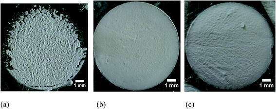
The optical micrographs of the deposited films are illustrated in Fig. 5. Even though the zeta potential (18 mV) was high for the I2 acetone based suspension, the morphology of the obtained KNN films is poor. However, when TEA was used with pH of 9.1 and a zeta potential of 1.34 mV, the morphology of the deposited film at 100 V for 1 min is very regular, with a very smooth surface and presenting no surface defects. With the increase of deposition voltage to 200 V the quality of the films deteriorate, which might be due to the high mobility of the particles, which does not allow them time to settle down on the substrate, hence resulting in a poor morphology of the deposited films.
However, it is strange that with such a low zeta values (1.34 mV) obtained KNN films had smooth and uniform morphology. One possible explanation for the formation of very uniform KNN films from acetone with TEA might be related to the hygroscopic nature of KNN. In order to confirm the presence of –OH ions on the surface of KNN, FTIR was performed on the KNN particles (Fig. 6(a)). The high intensity transmittance band at 3444 cm−1 clearly suggests the presence of hydroxyl (–OH) group. Other transmittance peaks detected at 669 and 362 cm−1 are the characteristic peaks of KNN arising from the oxygen octahedra. Moreover, the peak observed at 1637 cm−1 may be attributed to carboxyl groups formed as reaction products of organic combustion during the heat treatment of KNN powders. On the other hand, TEA has unique properties due to the presence of amine and alcohol groups; its basic nitrogen atom with a lone pair accounts for the weak basic character of TEA, whereas its terminal hydroxyl groups may undergo hydrogen bonding with neighbouring OH groups. When TEA is added to the KNN suspension, being a weak base it increases the pH of the suspension. In addition, some TEA molecules become bonded to the surface of the KNN particles, probably through hydrogen bonding between the OH groups of TEA and chemically adsorbed OH groups on KNN, as detected by FTIR. As the zeta potential of KNN suspensions with minor amounts of TEA is a modest but positive value (+1.34 mV), the overall effect of TEA adsorption is the development of a net positive charge on the surface of KNN particles. Under the influence of the applied external electric field, KNN charged particles move towards the counter charged electrode, where they overcome the repulsive forces due to the electrostatic repulsion, and form a thick layer. The presence of adsorbed TEA molecules on the KNN particle surface is thought to promote the bonding of adjacent KNN particles stacking on the substrate via hydrogen bonding. Because of such adhesive properties,32 imparted by adsorbed TEA, KNN particles attach to each other strongly and uniformly, resulting in a very smooth KNN film surface.
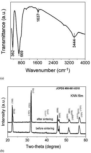 | ||
| Fig. 6 (a) FTIR spectra of KNN powders and (b) XRD spectra of the KNN thick film deposited in acetone with TEA before and after sintering. | ||
Both potassium and sodium can undergo leaching into the acetone suspension, and this can affect the stoichiometry or the formation of secondary phases in the sintered KNN films. Therefore, XRD was performed on KNN films before and after sintering (Fig. 6(b)). From the XRD analysis there are no significant changes in the diffraction patterns of non sintered and sintered KNN films. The main XRD peaks of KNN are present, however, there are few extra peaks observed for as deposited KNN thick film and sintered KNN films, when compared with KNN powders, at 25.58, 29.39 and 34.35 2θ° that correspond to K3Nb5.4O15 (pdf. #04-010-8979). The presence of this secondary phase might be due to some leaching of KNN in suspension. The other peak at 39.82 2θ° (pdf. #04-011-9036) is associated to the platinum substrate.
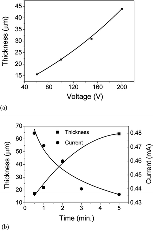
Uniform films of KNN can be obtained from acetone suspension with TEA. Therefore, the deposition thickness of KNN films was studied as a function of time and voltage (Fig. 7). It was observed that for a constant deposition time, the film thickness increases more or less linearly with the voltage, whereas, for a constant voltage, the film thickness increases linearly with the deposition time until 2 min (40 μm), and then starts to deviate from linearity. These observations are in agreement with the Hamaker relation. Hamaker correlated the deposit yield (w) with the electric field strength (E), the electrophoretic mobility (μ), the area of the electrode (A) and the particle mass concentration in the suspension (C) through the following equation:33
The decrease of the rate of film thickness increase with deposition time is the result of the insulating layer that is formed as KNN particles deposit on the substrate (counter electrode), which results in the decrease of the electric field. Indeed the electric current of the suspension measured during the EPD process as a function of deposition time and illustrated in Fig. 7(b) decreases exponentially (from 0.48 to 0.435 mA).
The observed decrease in the electric current might also be related to the decrease in the charged species concentration in the suspension, as the film is formed in the counter electrode.
The microstructure of KNN particles and films is illustrated in Fig. 8. Calcined KNN powders possess a cuboid-like shape with average size around 1 μm (Fig. 8(a)). Fig. 8(b) and (c) presents the microstructure of two KNN films sintered at 1100 °C for 2 h: one without iso-static pressing (Fig. 8(b)), and the other one with iso-static pressing (Fig. 8(c)). As expected, films isostatically pressed are denser when compared to those not pressed. The cross-section of isostatically pressed KNN films reveals a dense and uniform film section, without any abrupt interface between the film and the substrate (Fig. 8(d)).
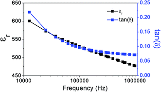
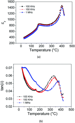
The dielectric properties of the KNN thick films derived from acetone with TEA at 100 V for 1 min are presented in Fig. 9 and 10. Table 2 compiles the data obtained in this work and includes also reported electrical data for KNN single crystals, ceramics and thick films prepared from other methods. Properties of PZT are also included in the table, as a reference material. At room temperature, the relative permittivity is around 393 (1 MHz) (Fig. 9), which is close to the values reported for KNN ceramics of around 300–400. The dielectric losses are around 0.07 (1 MHz). Fig. 10 depicts the relative permittivity (εr) as a function of the temperature (acquired during cooling). Two peaks were observed at 180 °C and 400 °C, corresponding to the phase transitions from monoclinic to tetragonal and from tetragonal to cubic, respectively, which are slightly lower than the transition temperatures reported for equivalent KNN ceramics (220 °C and 420 °C).34 Fig. 10(b) shows the dielectric loss tan(δ) as a function of temperature during cooling. Two peaks can be seen at 156 °C and 330 °C, corresponding to the phase transitions from monoclinic to tetragonal and from tetragonal to cubic, respectively. These values are also lower than those reported for KNN ceramics (170 °C and 392 °C). The slight lowering of the phase transition temperature for KNN films might be related to the stresses due to substrate clamping and grain size in the thick films, as reported before.35 Similar observation was reported for KNN thin films fabricated by sol gel.36 The dielectric losses of the KNN thick film were 0.07 at 1 MHz, which is higher than that reported for KNN ceramics (0.04 at 1 MHz).34 The dielectric performance of EPD KNN films is quite similar to that reported for equivalent ceramics.
![[thin space (1/6-em)]](https://www.rsc.org/images/entities/char_2009.gif) :
:![[thin space (1/6-em)]](https://www.rsc.org/images/entities/char_2009.gif) 1) single crystals, ceramics and thick films of this work and previously reported. As a comparison the data for doped KNN and PZT are also included
1) single crystals, ceramics and thick films of this work and previously reported. As a comparison the data for doped KNN and PZT are also included
| Material | εr (Troom) | Tc (°C) | tan![[thin space (1/6-em)]](https://www.rsc.org/images/entities/char_2009.gif) δ δ |
d33 (pC N−1) | Reference |
|---|---|---|---|---|---|
KNN (1![[thin space (1/6-em)]](https://www.rsc.org/images/entities/char_2009.gif) : :![[thin space (1/6-em)]](https://www.rsc.org/images/entities/char_2009.gif) 1) thick films by EPD 1) thick films by EPD |
393 (1 MHz) | 400 | 0.07 (1 MHz) | 40 | Present work |
| KNN thick films by sol gel | 250 (1 kHz) | 1.3 | 18 | 37 | |
| KNN thick films by aerosol deposition | 116 (as-deposited) 545 (annealed) (1 kHz) | 0.04 | 38 | ||
KNN (1![[thin space (1/6-em)]](https://www.rsc.org/images/entities/char_2009.gif) : :![[thin space (1/6-em)]](https://www.rsc.org/images/entities/char_2009.gif) 1) ceramics 1) ceramics |
290 (1 kHz) | 0.04 (1 kHz) | 80 | 34 | |
KNN (1![[thin space (1/6-em)]](https://www.rsc.org/images/entities/char_2009.gif) : :![[thin space (1/6-em)]](https://www.rsc.org/images/entities/char_2009.gif) 1) ceramics 1) ceramics |
436 (1 kHz) | 417 | <0.5 (1 kHz) | 74 | 39 |
KNN (1![[thin space (1/6-em)]](https://www.rsc.org/images/entities/char_2009.gif) : :![[thin space (1/6-em)]](https://www.rsc.org/images/entities/char_2009.gif) 1) hot pressed ceramics 1) hot pressed ceramics |
420 (1 kHz) | 160 | 40 | ||
| KNN-LF4 textured ceramics | 1570 (1 kHz) | 253 | 410 | 3 | |
KNN (1![[thin space (1/6-em)]](https://www.rsc.org/images/entities/char_2009.gif) : :![[thin space (1/6-em)]](https://www.rsc.org/images/entities/char_2009.gif) 1) single crystals [001] 1) single crystals [001] |
300 (1 kHz) | 429 | 160 | 41 | |
KNN (1![[thin space (1/6-em)]](https://www.rsc.org/images/entities/char_2009.gif) : :![[thin space (1/6-em)]](https://www.rsc.org/images/entities/char_2009.gif) 1) single crystals [001] 1) single crystals [001] |
240 (100 kHz) | 393 | 0.02 (100 kHz) | 160 | 42 |
KNN (1![[thin space (1/6-em)]](https://www.rsc.org/images/entities/char_2009.gif) : :![[thin space (1/6-em)]](https://www.rsc.org/images/entities/char_2009.gif) 1) single crystals [1 1) single crystals [1![[3 with combining macron]](https://www.rsc.org/images/entities/char_0033_0304.gif) 1] 1] |
1015 (100 kHz) | 410 | 0.01 (100 kHz) | 50 | 43 |
KNN (1![[thin space (1/6-em)]](https://www.rsc.org/images/entities/char_2009.gif) : :![[thin space (1/6-em)]](https://www.rsc.org/images/entities/char_2009.gif) 1) single crystals [ 1) single crystals [![[3 with combining macron]](https://www.rsc.org/images/entities/char_0033_0304.gif) ![[2 with combining macron]](https://www.rsc.org/images/entities/char_0032_0304.gif) ![[3 with combining macron]](https://www.rsc.org/images/entities/char_0033_0304.gif) ] ] |
650 (100 kHz) | 409 | 0.01 (100 kHz) | — | 43 |
| PZT (type Navy I) Morgan type 402 hard ceramics | 1250, 1200 (1 kHZ) | 325, 320 | 0.4 0.003 (1 kHz) | 290, 285 | 44 and 45 |
| PZT (type VI) soft ceramics | 3400 | 180 | 1.70 (1 kHz) | 650 | 44 |
The piezoelectric coefficient (d33) of poled KNN thick films (KNN + Pt foil) was measured by Berlincourt method, and an average value of 40 pC N−1 was recorded. This value is close to values previously reported for KNN thick films, and also measured by Berlincourt meter (18 pC N−1 and 44 pC N−1)36,37 and in other studies where d33 was measured by scanning vibrometer (35 pm V−1).46 This value is lower than those reported for equivalent ceramics, with the lowest d33 reported for monophasic KNN being 80 pC N−1,34 and the highest being 160 pC N−1.40 Composition, porosity and presence of a non-piezoelectric substrate (Pt) may account for these differences.
For bulk materials, the most commonly used method to assess piezoelectric coefficients is the Berlincourt meter, in which a dynamically varying load is applied and the electrical energy generated by the element measured per unit of mechanical stress applied. However, it is generally considered that this method is not adequate to characterize thin films, because it is usually difficult to produce a homogeneous uniaxial stress on a thin film deposited on a thick substrate without also generating a bending effect, which would produce a large amount of charge through the transverse piezoelectric effect.47 In the present case, although the determined d33 values are affected by the substrate, because the films are thick (10 to 60 μm) this effect might be minimised.
Conclusions
K0.5Na0.5NbO3 (KNN) thick films, between 10–60 μm in thickness, were successfully fabricated on platinum foils by electrophoretic deposition. Acetone with triethanolamine (TEA) was found to be a suitable suspension medium for the deposition of KNN, and the addition of TEA to be crucial for obtaining high quality films. The results of this work clearly show that besides the particle charge in suspension (quantified by zeta potential), the mobility and surface functionalization of the particles are also critical for a good quality deposited film. At room temperature, the relative permittivity and dielectric losses of 42 μm thick KNN films, iso-statically pressed at 200 MPa for 5 min and sintered at 1100 °C for 2 h, are 397 and 0.07 at 1 MHz, respectively. At 200 °C, these same films exhibit a relative permittivity of 820 and loss tangent of 0.045 at 1 MHz. These films exhibit a similar dielectric performance as their ceramics counterparts. This work proves that EPD is a suitable low cost, versatile and promising technology for the preparation of KNN thick films with tailored specifications to the appropriate application.Acknowledgements
The authors acknowledge Fundação para a Ciência e a Tecnologia (FCT), Fundo Europeu de Desenvolvimento Regional Portugal (FEDER), QREN-COMPETE Portugal, and the Associate Laboratory CICECO (PEst-C/CTM/LA0011/2013) for funding support. Amit Mahajan acknowledges FCT for financial support (SFRH/BD/65415/2009). Morgane Dolhen is thankful to the University of Limoges for financial support within ERASMUS MUNDUS. Many thanks to Dr R. C. Pullar for helping with the English language corrections.References
- P. Panda, J. Mater. Sci., 2009, 44, 5049–5062 CrossRef CAS PubMed.
- H. Birol, D. Damjanovic and N. Setter, J. Am. Ceram. Soc., 2005, 88, 1754–1759 CrossRef CAS PubMed.
- Y. Saito, H. Takao, T. Tani, T. Nonoyama, K. Takatori, T. Homma, T. Nagaya and M. Nakamura, Nature, 2004, 432, 84–87 CrossRef CAS PubMed.
- X. Wang, J. Wu, D. Xiao, J. Zhu, X. Cheng, T. Zheng, B. Zhang, X. Lou and X. Wang, J. Am. Chem. Soc., 2014, 136, 2905–2910 CrossRef CAS PubMed.
- R. E. Jaeger and L. Egerton, J. Am. Ceram. Soc., 1962, 45, 209–213 CrossRef CAS PubMed.
- B. Jaffe, W. R. Cook and H. Jaffe, Piezoelectric Ceramics, Academic, New York, 2nd edn, 1971, pp. 135–156 Search PubMed.
- A. Ahtee, M. Ahtee, A. M. Glazer and A. W. Hewat, Acta Crystallogr., Sect. B: Struct. Crystallogr. Cryst. Chem., 1976, 32, 3243–3246 CrossRef.
- G. Shirane, R. Newnham and R. Pepinsky, Phy. Rev., 1954, 96, 581–588 CrossRef CAS.
- M. Asif Rafiq, P. Supancic, M. Elisabete Costa, P. M. Vilarinho and M. Deluca, Appl. Phys. Lett., 2014, 104, 011902 CrossRef PubMed.
- J. Tellier, B. Malic, B. Dkhil, D. Jenko, J. Cilensek and M. Kosec, Solid State Sci., 2009, 11, 320–324 CrossRef CAS PubMed.
- K. Wang and J.-F. Li, Appl. Phys. Lett., 2007, 91, 262902 CrossRef PubMed.
- L. Wang, K. Yao and W. Ren, Appl. Phys. Lett., 2008, 93, 092903 CrossRef PubMed.
- T. Shiraishi, H. Einishi, S. Yasui, H. Funakubo, T. Hasegawa, M. Kurosawa, M. Ishikawa, H. Uchida and Y. Sakashita, J. Korean Phys. Soc., 2013, 62, 1055–1059 CrossRef CAS.
- T. Shiraishi, H. Einishi, S. Yasui, M. Ishikawa, T. Hasegawa, M. Kurosawa, H. Uchida, Y. Sakashita and H. Funakubo, J. Ceram. Soc. Jpn., 2013, 121, 627–631 CrossRef CAS.
- T. Lusiola, N. Chelwani, F. Bortolani, Q. Zhang and R. A. Dorey, Ferroelectrics, 2011, 422, 50–54 CrossRef CAS.
- A. R. Boccaccini and I. Zhitomirsky, Curr. Opin. Solid State Mater. Sci., 2002, 6, 251–260 CrossRef CAS.
- I. Corni, M. P. Ryan and A. R. Boccaccini, J. Eur. Ceram. Soc., 2008, 28, 1353–1367 CrossRef CAS PubMed.
- J. Van Tassel and C. A. Randall, Thin/thick piezoelectric films by electrophoretic deposition, 5th Annual International Symposium on Smart Structures and Materials, 1998 Search PubMed.
- A. Wu, P. Vilarinho, S. Srinivasan, A. I. Kingon, I. M. Reaney, D. Woodward, A. Ramos and E. Alves, Acta Mater., 2006, 54, 3211–3220 CrossRef CAS PubMed.
- Z. Fu, A. Wu, P. M. Vilarinho, A. I. Kingon and R. Wordenweber, Appl. Phys. Lett., 2007, 90, 052912–052913 CrossRef PubMed.
- X. Su, A. Wu and P. M. Vilarinho, Scr. Mater., 2009, 61, 536–539 CrossRef CAS PubMed.
- P. M. Vilarinho, A. Mahajan, I. Sterianou and I. M. Reaney, J. Eur. Ceram. Soc., 2012, 32, 4319–4326 CrossRef CAS PubMed.
- A. Hosang, P. Jung-Hyun, K. Seon-Bae and K. Dong-Joo, Applications of Ferroelectrics, 2009. ISAF 2009. 18th IEEE International Symposium on the, 2009.
- L. Besra and M. Liu, Prog. Mater. Sci., 2007, 52, 1–61 CrossRef CAS PubMed.
- P. M. Vilarinho, Z. Fu, A. Wu and A. I. Kingon, J. Phys. Chem. B, 2013, 117, 1670–1679 CrossRef CAS PubMed.
- F. Bouyer and A. Foissy, J. Am. Ceram. Soc., 1999, 82, 2001–2010 CrossRef CAS PubMed.
- O. O. Van der Biest and L. J. Vandeperre, Annu. Rev. Mater. Sci., 1999, 29, 327 CrossRef CAS.
- I. Zhitomirsky, J. Mater. Sci. Lett., 1998, 17, 2101–2104 CrossRef CAS.
- P. S. S. Nicholson, P. Sarkar and X. Huang, J. Mater. Sci. Lett., 1993, 28, 6274–6278 CrossRef CAS.
- H. Xu, I. P. Shapiro and P. Xiao, J. Eur. Ceram. Soc., 2010, 30, 1105–1114 CrossRef CAS PubMed.
- M. Ghorbani and M. Roushan Afshar, Int. J. Mod. Phys. B, 2008, 22, 2989–2994 CrossRef CAS.
- http://www.dow.com/amines/prod/ethano-tea.htm, retrived on 20 June 2014.
- H. C. Hamaker, Trans. Faraday Soc., 1940, 35, 279–287 RSC.
- L. Egerton and D. M. Dillon, J. Am. Ceram. Soc., 1959, 42, 438–442 CrossRef CAS PubMed.
- R. A. Wolf and S. Trolier-McKinstry, J. Appl. Phys., 2004, 95, 1397–1406 CrossRef CAS PubMed.
- J. Pavlič, B. Malič and T. Rojac, J. Eur. Ceram. Soc., 2014, 34, 285–295 CrossRef PubMed.
- T. Lusiola, N. Chelwani, F. Bortolani, Q. Zhang and R. Dorey, Ferroelectrics, 2011, 422, 50–54 CrossRef CAS.
- J. Ryu, J.-J. Choi, B.-D. Hahn, D.-S. Park, W.-H. Yoon and K.-H. Kim, Appl. Phys. Lett., 2007, 90, 152901 CrossRef PubMed.
- M. A. Rafiq, Electromechanical properties of engineered lead free potassium sodium niobate based materials, University of Aveiro, 2014 Search PubMed.
- R. Jaeger and L. Egerton, J. Am. Ceram. Soc., 1962, 45, 209–213 CrossRef CAS PubMed.
- M. A. Rafiq, V. Costa, M. Elisabete and P. M. Vilarinho, Sci. Adv. Mater., 2014, 6, 426–433 CrossRef CAS PubMed.
- D. Lin, Z. Li, S. Zhang, Z. Xu and X. Yao, Solid State Commun., 2009, 149, 1646–1649 CrossRef CAS PubMed.
- H. Uršič, A. Benčan, M. Škarabot, M. Godec and M. Kosec, J. Appl. Phys., 2010, 107, 033705 CrossRef PubMed.
- http://www.americanpiezo.com/apc-materials/piezoelectric-properties.html, retrieved on 28 June 2011.
- http://www.morganelectroceramics.com/materials/piezoelectric/, retrieved on 28 June 2011.
- L. Wang, W. Ren, K. Yao, P. Shi, X. Wu and X. Yao, Ceram. Int., 2012, 38(suppl 1), S291–S294 CrossRef CAS PubMed.
- Z. Huang, Q. Zhang, S. Corkovic, R. Dorey and R. W. Whatmore, IEEE Transactions on Ultrasonics, Ferroelectrics, and Frequency Control, 2006, 53, 2287–2293 CrossRef.
| This journal is © The Royal Society of Chemistry 2015 |

