DOI:
10.1039/C4RA14871A
(Paper)
RSC Adv., 2015,
5, 26985-26990
Anisotropic terahertz response of stretch-aligned composite films based on carbon nanotube–SiC hybrid structures†
Received
19th November 2014
, Accepted 9th March 2015
First published on 10th March 2015
Abstract
Well-organized CNT–SiC hybrid structures were prepared by a floating catalytic chemical vapor deposition (CCVD) process. The aligned CNT–based composite materials were also fabricated by simply stretching. Gelatin and CNT–SiC hybrid structures were taken as the matrix and fillers, respectively. The alignment of CNT–SiC hybrids and anisotropic properties of the composite materials were discussed using the detection of THz time-domain spectroscopy technology. The results indicated that the anisotropic properties of CNT–SiC hybrid based composite films are better than the case of pure MWCNTs. The unique structure of the hybrids not only largely favors the dispersion of CNTs in a polymer matrix, but also favors the alignment of CNTs in the composites by stretching. The CNT-based composite films with further improvement in anisotropy are highly desirable for various modern applications in the electrical and optical industry (such as in polarizers).
1. Introduction
Carbon nanotubes (CNTs) have attracted increasing interest and attention worldwide due to their unique structure, and extraordinary physical and chemical properties.1–4 Extensive potential applications have been proposed in many fields such as composite materials, nanometer-sized electronic devices, detectors, polarizers,5–7 sensors8–10 and the probes of electron microscopes.11–13 In particular, using CNT as a filler material to fabricate the composites is one of the most realizable industrial applications in the short term, and the composites usually exhibit superior multifunctional properties.14–17 However, there are some difficulties in manufacturing CNT-based composites due to their nanoscale characteristics. For example, pure CNTs are not easy to disperse in the composites and often tangle together due to the high aspect ratio and the strong pair interaction (van der Waals). This problem could be resolved in an efficient way, that is to fabricate multi-scale hybrid structures by growing CNTs on micrometer-scale materials. Bozlar M. et al. reported that the epoxy composites used CNT–Al2O3 hybrids as filler can have one order of magnitude higher thermal conductivity value than those composites adding pure CNTs with equal content.18 Recently, our group reported that the poly(vinylidene fluoride) (PVDF) composites based on the CNT–SiC micro/nano hybrids exhibited a much low percolation threshold, and the AC conductivity was enhanced significantly.19 The main idea of these works is that the microscale nature of the CNT hybrid, compared to pure CNTs, greatly favors the homogeneous distribution in the composites due to increasing size.
Many groups investigated the THz response of single (double)-walled CNTs based composites.20–23 In addition, CNTs in the composite could be arranged in certain direction through some processing technologies (e.g. stretching), thus the composite materials have anisotropic properties. For example, in the important publication by Y. Kim et al. substantial alignment of isolated individual single-walled CNTs has been achieved by mechanically stretching the composite films, and the composite materials presented highly polarized absorption.24 A.V. Okotrub et al. reported that the composite materials have been prepared by repeated forge rolling of polystyrene and their anisotropic terahertz responses were investigated.25 Based on the anisotropic property, CNTs-based composite materials will have a wide range of applications. However, the anisotropic properties of the composites with different CNT organization modes (CNT types, CNT content, etc.) were rarely investigated systematically.
In this paper, we obtained special CNT–SiC hybrid structure by single-directionally growing CNTs on plate-like SiC microparticles during chemical vapor deposition process. The anisotropic composite films were prepared by mechanically stretching the gelatin films filled with various CNT materials. A systematic study on the anisotropy of the composite films was presented by utilizing THz time-domain spectroscopy (THz-TDS) detection. The anisotropic terahertz responses of the composites containing CNT–SiC hybrids comparing with pure CNTs were emphasized, and the effect of CNT content on the anisotropy of the composite films was also explored.
2. Experimental methods
2.1 Synthesis of hybrid structure
The synthesis of hybrid structure was carried out by catalytic chemical vapor deposition (CCVD). The detailed procedure was as described in previous work.19 Briefly, the plate-like SiC microparticles were used as the substrate, and one layer of particles were homogeneously dispersed on the surface of a quartz plate, which was then put into the center of a quartz tube (110 cm long, inner diameter 50 mm). The substrate was heated to the set temperature by a horizontal tube furnace under the carrier gases (argon and hydrogen) with varied flow rate ratios. Acetylene was used as carbon source, and the flow rate was kept at 30 ml min−1. The catalyst precursor ferrocene (Fe(C5H5)2) was dissolved in xylene (C8H10) at 0.05 g ml−1. The CNT–SiC hybrid structures were grown on SiC substrates at 600 °C during 10 min.
2.2 Preparation of composite material
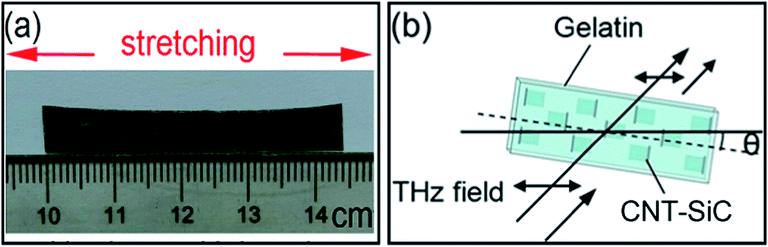
CNT–SiC hybrid structure was used as a starting material. Granular gelatin from alkali-processed bovine bone was obtained from Wako Chemicals. An aqueous solution was obtained by dissolving 4 g of gelatin in 100 ml of deionized water and then continuously heated and stirred at 65 °C for one hour. CNT hybrids were dispersed in aqueous solution and heated at 65 °C to concentrate the solution.26 Then CNT/gelatin films were obtained by casting the solution in the Petri dish and dried at room temperature for 24 hours. Gelatin was chosen because its solution undergoes gelatin at 37 °C during the cooling, which was expected to prevent the aggregation (or rebundling) of CNTs.24 Dried films were soaked in ethanol for 10 min and then taken out of the Petri dish. Thus obtained free-standing films were swollen in a mixture of water and ethanol (3![[thin space (1/6-em)]](https://www.rsc.org/images/entities/char_2009.gif) :2) for 15 min and fixed on a glass substrate by stretching. After being stretched (to 2.5 times of the original length), the films were dried in air under the constant elongation. The sample obtained was shown in Fig. 1a. The thickness of the sample films was about 0.25 (±0.02) mm. Also we purchased the multi-walled carbon nanotubes (MWCNT, diameter: ∼8 nm; length: 10–30 μm; purity: >95%) from Beijing Dknano S&T Ltd to fabricate the MWCNT/gelatin composite films as a comparison.
:2) for 15 min and fixed on a glass substrate by stretching. After being stretched (to 2.5 times of the original length), the films were dried in air under the constant elongation. The sample obtained was shown in Fig. 1a. The thickness of the sample films was about 0.25 (±0.02) mm. Also we purchased the multi-walled carbon nanotubes (MWCNT, diameter: ∼8 nm; length: 10–30 μm; purity: >95%) from Beijing Dknano S&T Ltd to fabricate the MWCNT/gelatin composite films as a comparison.
 |
| | Fig. 1 (a) The real figure of the stretched CNT–SiC/gelatin film. (b) Sketch of the experimental configuration used, showing the interaction between the CNTs-based composite film and the linearly polarized THz electric field. | |
2.3 Characterization of sample
The collected samples were characterized by the following techniques: scanning electron microscope (SEM, LEO Gemini 530), transmission electron microscope (TEM, JEOL JEM-3010 at 300 kV), and a custom-designed THz-TDS system (Ti: Sapphire femtosecond laser: Maitai Spectra-Physics, repetition rate 80 MHz, pulse width 70 fs, central wavelength 800 nm). As schematically shown in Fig. 1b, the CNTs-based composite film was rotated about the propagation direction of the THz wave, which changed the angle, θ, between the stretching direction and the polarization direction of the THz electric field. Here, we chose two directions to test, θ = 0° and θ = 90° (the stretching direction parallel or perpendicular to the polarization direction of the THz electric filed, respectively).
3. Results and discussion
In this paper, we manufactured the various CNTs-based composite materials. In order to understand the performance of the composites, we comparatively analyzed the THz transmission spectroscopy about the composites based on the different organization modes of CNTs. Also we discussed the relationship between the THz transmission spectroscopy and the alignment of CNTs in the composite film by analyzing the distribution of CNTs on the cross section of polymer.
3.1 Morphology of CNT–SiC hybrid structure
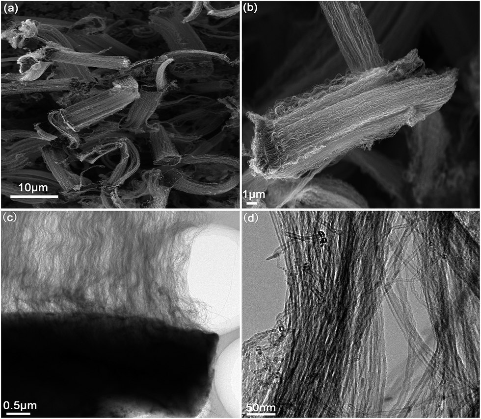
The diameter, length and number density of CNT could influence the CNT alignment in the hybrids and thus the CNT distribution in the composites. The bigger diameter, shorter length and higher number density of CNT favored straighter CNT array.19,27 The reaction conditions can influence the structure (diameter, length, number density, etc.) of CNT–SiC hybrids. For examples, higher H2 ratio (0.3 L min−1) favored the growth of multi-directions hybrids,19 which resulted in the decrease of CNT alignment degree. Therefore, we chose single-direction hybrids grown at 600 °C for 10 min with the fixed gas ratio (Ar:H2:C2H2 = 0.9:0.1:0.03 L min−1). SEM and TEM images of the hybrids were shown in Fig. 2. As shown in Fig. 2(a and b), the CNT–SiC hybrid structure was micro-scale structure. Compared with the independent CNTs, the hybrid structures were more helpful for dispersing and processing in the composites due to the increasing size. The CNT bundles perpendicular to the plate-like SiC particles were grown uniformly along one direction, and the average length of CNTs was about 20 μm. The special structures of CNT hybrids were easily adjusted to certain directions in composites and produced some direction-related properties. From the TEM pictures in Fig. 2(c and d), we can also see that the aligned CNTs were grown on the surface of the SiC substrate, and the diameter of each nanotube was in the range of 8–10 nm.
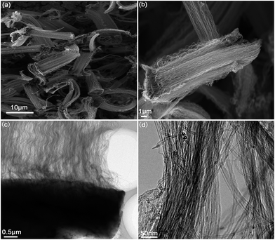 |
| | Fig. 2 (a and b) SEM images and (c and d) TEM images of CNT–SiC hybrid structure prepared at 600 °C for 10 min with Ar:H2:C2H2 = 0.9:0.1:0.03 L min−1. | |
3.2 THz transmission of various CNTs-based composites
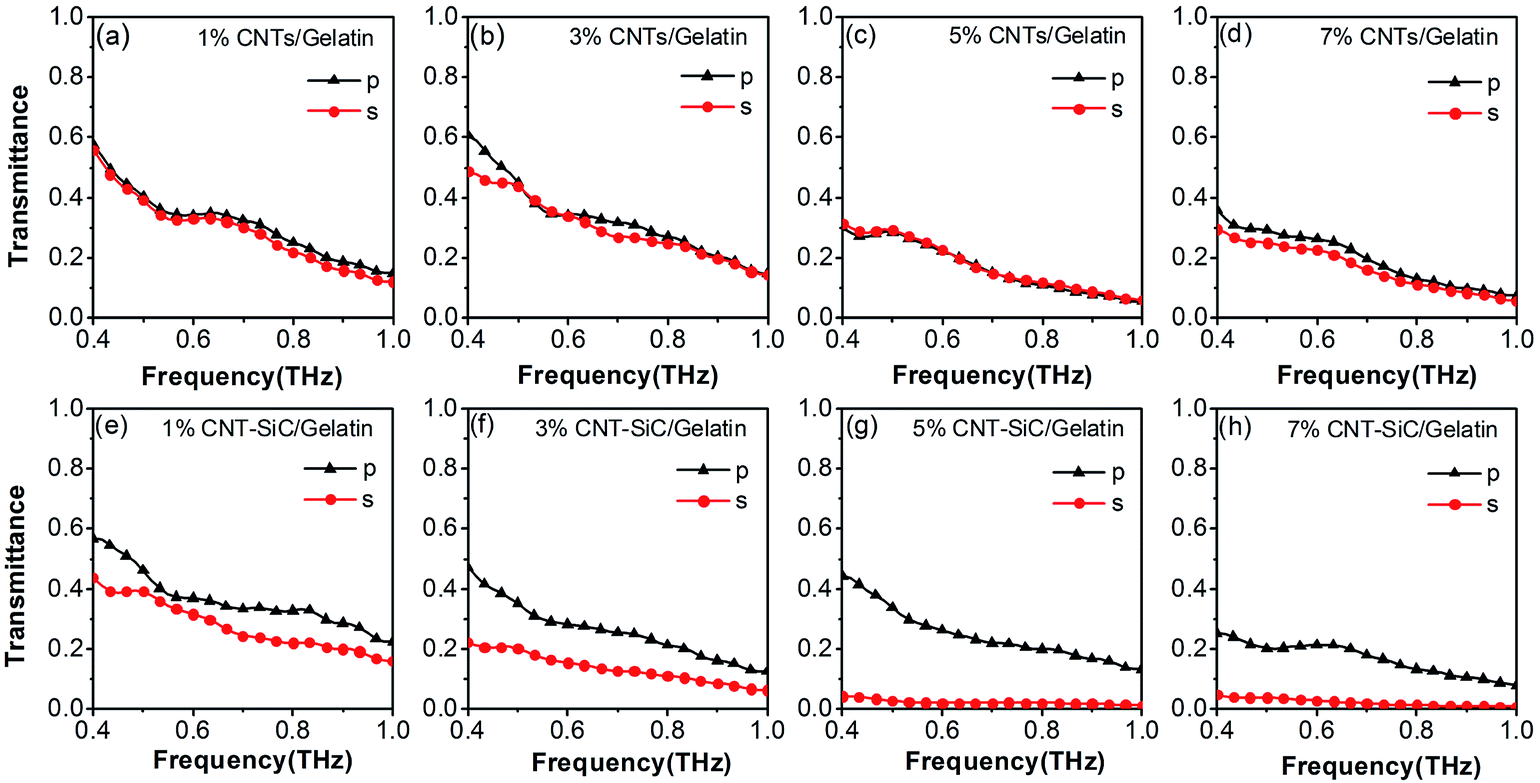
The THz setup we utilized to study the samples was a custom-designed time-domain THz spectroscopy system as shown in Fig. S1 (in the ESI†). The THz pulses were generated by a photoconductive antenna under the excitation of a 70 fs laser which its center wavelength is 800 nm and the repetition rate is 80 MHz. Then the pulses were detected by an electro-optic sampling with a ZnTe crystal. The all optical path was in the N2 atmosphere to avoid the effect of the humidity. The THz beam was already highly linearly polarized. To extract the spectral features of our CNTs-based composite films, we obtained the transmittance spectra calculated after Fourier transformation of the time domain signals in the range of 0.4–1.0 THz. The transmittance was defined as T = |Es/Er|2, where Es and Er were the complex THz signals in the frequency domain after Fourier transform from their time-domain data for the sample and reference, respectively. THz absorption results on the pristine gelatin films and films with only SiC particles embedded in them were shown in the Fig. S2 (in the ESI†). We can see that the transmittance curves of SiC/gelatin composites in two directions nearly overlap with that of pure gelatin samples in the studied frequency range. The results indicate that the influence of SiC particles in our samples on the THz transmittance is negligible. Fig. 3 shows the THz transmittance spectra of CNTs-based composite materials. Black lines with triangle marks are for the samples with THz polarization perpendicular to the stretching direction, and the red lines with circle marks are for the parallel case. For Fig. 3(a and d), the concentrations of MWCNTs in the composite materials are 1%, 3%, 5%, 7%, respectively. The transmittance of perpendicular case is a little higher than that of the parallel case, and the gaps of transmittance between the two cases are very small even when the concentration of MWCNTs in the composite film increases to 7%. The reason may be that, although the MWCNTs in composite materials will be aligned after stretching and the composites may have anisotropic properties, aggregated MWCNTs in the composites degrades the alignment of MWCNTs in the composites. For Fig. 3(e–h), the concentrations of CNT–SiC hybrid structure in the gelatin polymers are 1%, 3%, 5%, 7%, respectively. Compared with the Fig. 3(a–d), the transmittance of the composite films of the perpendicular case is higher than that of the parallel case, and the gaps of transmittance between the two cases are obvious. The result indicates that the alignment of the CNT–SiC hybrid structure in the films is better than the case of pure MWCNTs. We can include that the alignment degree and the dispersion state of the CNT–SiC hybrids in the composite materials are better than the case of pure MWCNTs due to the increasing size. Also, the gap of transmittance between the two directions firstly increases with the content of the CNT–SiC hybrid structures and reaches the maximum at 5%, and then decreases a little when the concentration of the hybrids further increases to 7%. More detailed explanation about this result will be given in the following section.
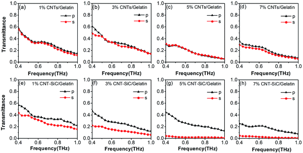 |
| | Fig. 3 (a–d) THz transmittance spectra of MWCNTs/gelatin films with the concentration of MWCNTs are for 1%, 3%, 5%, 7%. (e–g) THz transmittance spectra of CNT–SiC/gelatin films with the concentration of CNT–SiC are for 1%, 3%, 5%, 7%. Black lines with triangle marks are for the perpendicular case, and red lines with circle marks are for the parallel case. | |
In addition, to quantify the degree of alignment of CNTs in the composites from these THz transmission data, we employ a data analysis procedure developed for studying anisotropic optical properties of CNTs in the optical range.28–33 We introduce the isotropic absorbance A0, defined as A0 = (A‖ + 2A⊥)/3, where A‖ is the parallel absorbance and A⊥ is the perpendicular absorbance.34 This physical quantity represents the absorbance expected if the nanotubes were randomly oriented. Finite alignment moves up (down) A‖(A⊥) with respect to A0 and induces a finite linear dichroism, LD = A‖ − A⊥. However, it is the reduced linear dichroism, LDr ≡ LD/A0, that provides a normalized measure of alignment. For example, LD increases with the film thickness, while LDr remains the same.5 The degree of alignment of CNTs in the composites can be expressed by the value of LDr (=0 when the nanotubes are randomly oriented and =3 when the nanotubes are perfectly aligned) and increases with the LDr. Fig. 4 shows the LDr of CNTs-based composite materials. Black lines with the square marks are for the samples with the CNT concentration of 1%, red lines with circle marks are for 3%, blue lines with triangle marks are for 5%, and magenta lines with star marks are for 7%, respectively. For Fig. 4a, pure MWCNTs were used as the filler in the composite materials. We can see that the LDr curves for the composites with different CNT concentrations in the range of 0.4–1.0 THz are centralized together, and all the LDr values are very small (near the 0). This result indicates that pure MWCNTs in the composites are almost randomly oriented even after being stretched. The reason may be that pure MWCNTs due to the smaller size are always entangled together and not easily dispersed in the polymer matrix, which is responsible for the low alignment degree of pure MWCNTs in the composite materials. For Fig. 4b, the CNT–SiC hybrid structures were used as the filler in the composite materials. We can clearly see that the LDr curves for the composites with different CNT concentrations in the range of 0.4–1.0 THz are set apart well, and the LDr values of the composite films for the corresponding concentration are higher than those of pure MWCNTs. Also the LDr value of the composites firstly increases with the content of the CNT–SiC hybrids and reaches the maximum value (about 1.2) at 5%, and then decreases a little when the concentration of the hybrids further increases to 7%. The result about the change of LDr value with the CNT–SiC hybrid concentrations can be explained by the Fig. 5. At the lower contents of the CNT–SiC hybrids (e.g., =1%), although each CNT–SiC hybrid structure is aligned along the stretching direction in the composites, the effective connections between the CNT–SiC hybrid structures are not formed and thus the anisotropic properties of the composites are not obvious, as shown in Fig. 5a. With the increase of the concentration of CNT–SiC hybrid structures, the aligned connections will be gradually formed between the CNT–SiC hybrid structures, giving rise to a network at 5%, as shown in Fig. 5b.35 As a result, the anisotropic properties of CNT–SiC hybrids based composites approach to the best. However, if the concentration of CNT–SiC hybrid structures further increases, as show in Fig. 5c, the aligned connections will be destroyed and the axial directions of part of CNT–SiC hybrid structures are not parallel to the stretching direction due to the agglomeration of the CNT–SiC hybrid structures, and thus the anisotropic responses of the composite films will become weak. The results about the linear dichroism of the composites are consistent with the analysis of the transmittance of the composites above.
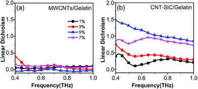 |
| | Fig. 4 Linear dichroism of (a) MWCNTs/gelatin polymer films and (b) CNT–SiC/gelatin polymer films. Black lines with the square marks, red lines with circle marks, blue lines with triangle marks, and magenta lines with star marks are for the samples with the CNT concentration of 1%, 3%, 5%, 7%, respectively. | |
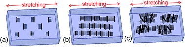 |
| | Fig. 5 Schematics of the distribution of CNT–SiC hybrids in the stretched composite materials with the different concentrations: (a) 1%, (b) 5%, (c) 7%. | |
3.3 The mechanism of terahertz response for various CNTs-based composite materials
For better understanding the terahertz response and the aligned nature for various CNTs-based composite materials, we analyzed the CNT distribution in the cross-surface (perpendicular to the stretching direction) of composite films, as shown in the Fig. 6. Fig. 6(a and b) show the cross-surface of pure MWCNTs based composite films. We can see that MWCNTs are randomly distributed in the gelatin polymer. The axial directions of part of MWCNTs are not perpendicular to the cross-surface and oriented along various directions, especially in the high-magnification SEM image marked by green ellipse. Also we can see some MWCNTs are aggregated or entangled together in the polymer. This could explain why there is no obvious difference about the terahertz responses of two directions (parallel and perpendicular to the stretching direction) for pure-MWCNTs based composite materials. Fig. 6(c and d) show the cross-surface of CNT–SiC hybrid structures based composite films. We can see that CNT–SiC hybrid structures are orientationally arranged in the gelatin polymer. The axial directions of most of CNTs in the hybrid structures are perpendicular to the cross-surface and oriented along the stretching directions, especially in the high-magnification SEM image marked by yellow circle. Also the CNT–SiC hybrid structures are rarely aggregated or entangled together in the composite films. The result indicates that with the SiC microplate fixing the aligned CNTs, the entanglement of nanotubes can be effectively prevented inside the polymer matrix. Therefore, we can conclude that the unique structure of hybrids not only largely favors the dispersion of CNTs in polymer matrix, but also favors the alignment of CNTs in the composites by stretching.
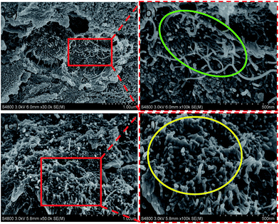 |
| | Fig. 6 SEM images of the fractured cross-surface of MWCNTs/gelatin composite film (a and b) and CNT–SiC/gelatin composite film (c and d). (b and d) are the enlarged images of the square part marked in (a and c), respectively. | |
4. Conclusion
Well-organized CNT–SiC hybrid structures were fabricated by growing CNT arrays on the plate-like SiC microparticles using the floating CCVD method. CNTs-based composite films were also prepared using CNTs–SiC hybrids as the filler and the gelatin polymer as the matrix, and the CNT–SiC hybrids were aligned in the composite films by stretching. Through the analysis of THz time-domain spectroscopy, there was an obvious difference about the terahertz responses between the two directions (parallel and perpendicular to the stretching direction), which made the composite films have the property of anisotropy. What is more, the anisotropic properties of CNT–SiC hybrids based composite films are better than the case of pure-MWCNTs due to the increasing size of the filler. The unique structure of hybrids not only largely favors the dispersion of CNTs in polymer matrix, but also favors the alignment of CNTs in the composites by stretching. The CNTs-based composite films with further improving the anisotropy are highly desirable for various modern applications in the electrical and optical industry (such as the polarizer). In addition, in virtue of the method this study proposed, we can simply examine the alignment of CNTs (conductive filler) in the composite materials without destroying the samples.
Acknowledgements
This work was supported by the National Natural Science Foundation of China (nos 11304249 and 61275105), Doctoral fund of Ministry of Education (no. 20126101120029), the Natural Science Foundation of Shaanxi Education Committee (12JK0990). Dr Xu acknowledges support from the open foundation of State Key Lab Incubation Base of Photoelectric Technology and Functional Materials (no. ZS12018).
References
- V. N. Popov, Mater. Sci. Eng., R, 2004, 43, 61–102 CrossRef.
- O. Kibis, M. Rosenau da Costa and M. Portnoi, Nano Lett., 2007, 7, 3414–3417 CrossRef CAS.
- Y. Wang, Q. Wu, W. Shi, X. He, X. Sun and T. Gui, Int. J. Infrared Millimeter Waves, 2008, 29, 35–42 CrossRef CAS PubMed.
- K. Batrakov, S. Maksimenko, P. Kuzhir and C. Thomsen, Phys. Rev. B: Condens. Matter Mater. Phys., 2009, 79, 125408 CrossRef.
- L. Ren, C. L. Pint, L. G. Booshehri, W. D. Rice, X. Wang, D. J. Hilton, K. Takeya, I. Kawayama, M. Tonouchi and R. H. Hauge, Nano Lett., 2009, 9, 2610–2613 CrossRef CAS PubMed.
- J. Kyoung, E. Y. Jang, M. D. Lima, H.-R. Park, R. O. Robles, X. Lepró, Y. H. Kim, R. H. Baughman and D.-S. Kim, Nano Lett., 2011, 11, 4227–4231 CrossRef CAS PubMed.
- L. Ren, C. L. Pint, T. Arikawa, K. Takeya, I. Kawayama, M. Tonouchi, R. H. Hauge and J. Kono, Nano Lett., 2012, 12, 787–790 CrossRef CAS PubMed.
- T. Fuse, Y. Kawano, T. Yamaguchi, Y. Aoyagi and K. Ishibashi, Nanotechnology, 2007, 18, 044001 CrossRef.
- S. Watanabe, N. Minami and R. Shimano, Opt. Express, 2011, 19, 1528–1538 CrossRef CAS PubMed.
- Z. Zhong, N. M. Gabor, J. E. Sharping, A. L. Gaeta and P. L. McEuen, Nat. Nanotechnol., 2008, 3, 201–205 CrossRef CAS PubMed.
- Y. Wang, K. Kempa, B. Kimball, J. Carlson, G. Benham, W. Li, T. Kempa, J. Rybczynski, A. Herczynski and Z. Ren, Appl. Phys. Lett., 2004, 85, 2607–2609 CrossRef CAS PubMed.
- R. H. Baughman, A. A. Zakhidov and W. A. de Heer, Science, 2002, 297, 787–792 CrossRef CAS PubMed.
- K. Kempa, J. Rybczynski, Z. Huang, K. Gregorczyk, A. Vidan, B. Kimball, J. Carlson, G. Benham, Y. Wang and A. Herczynski, Adv. Mater., 2007, 19, 421–426 CrossRef CAS.
- D. Qian, E. C. Dickey, R. Andrews and T. Rantell, Appl. Phys. Lett., 2000, 76, 2868–2870 CrossRef CAS PubMed.
- L. Ci and J. Bai, Compos. Sci. Technol., 2006, 66, 599–603 CrossRef CAS PubMed.
- M. Biercuk, M. C. Llaguno, M. Radosavljevic, J. Hyun, A. T. Johnson and J. E. Fischer, Appl. Phys. Lett., 2002, 80, 2767–2769 CrossRef CAS PubMed.
- M. B. Bryning, M. F. Islam, J. M. Kikkawa and A. G. Yodh, Adv. Mater., 2005, 17, 1186–1191 CrossRef CAS.
- M. Bozlar, D. He, J. Bai, Y. Chalopin, N. Mingo and S. Volz, Adv. Mater., 2010, 22, 1654–1658 CrossRef CAS PubMed.
- W. Li, J. Yuan, Y. Lin, S. Yao, Z. Ren, H. Wang, M. Wang and J. Bai, Carbon, 2013, 51, 355–364 CrossRef CAS PubMed.
- S. Kumar, N. Kamaraju, A. Moravsky, R. O. Loutfy, M. Tondusson, E. Freysz and A. K. Sood, Eur. J. Inorg. Chem., 2010, 27, 4363–4366 CrossRef.
- H. Nishimura, N. Minami and R. Shimano, Appl. Phys. Lett., 2007, 91, 011108 CrossRef PubMed.
- S. Kumar, N. Kamaraju, B. Karthikeyan, M. Tondusson, E. Freysz and A. K. Sood, J. Phys. Chem. C, 2010, 114, 12446–12450 CAS.
- T.-I. Jeon, K.-J. Kim, C. Kang, S.-J. Oh, J.-H. Son, K. H. An, D. J. Bae and Y. H. Lee, Appl. Phys. Lett., 2002, 80, 3403 CrossRef CAS PubMed.
- Y. Kim, N. Minami and S. Kazaoui, Appl. Phys. Lett., 2005, 86, 073103 CrossRef PubMed.
- A. Okotrub, V. Kubarev, M. Kanygin, O. Sedelnikova and L. Bulusheva, Phys. Status Solidi B, 2011, 248, 2568–2571 CrossRef CAS.
- M. J. O'connell, S. M. Bachilo, C. B. Huffman, V. C. Moore, M. S. Strano, E. H. Haroz, K. L. Rialon, P. J. Boul, W. H. Noon and C. Kittrell, Science, 2002, 297, 593–596 CrossRef PubMed.
- D. He, H. Li, W. Li, P. Haghi-Ashtiani, P. Lejay and J. Bai, Carbon, 2011, 49, 2273–2286 CrossRef CAS PubMed.
- M. Islam, D. Milkie, C. Kane, A. Yodh and J. Kikkawa, Phys. Rev. Lett., 2004, 93, 037404 CrossRef CAS.
- S. Zaric, G. N. Ostojic, J. Kono, J. Shaver, V. C. Moore, M. S. Strano, R. H. Hauge, R. E. Smalley and X. Wei, Science, 2004, 304, 1129–1131 CrossRef CAS PubMed.
- S. Zaric, G. N. Ostojic, J. Kono, J. Shaver, V. C. Moore, R. H. Hauge, R. E. Smalley and X. Wei, Nano Lett., 2004, 4, 2219–2221 CrossRef CAS.
- M. Islam, D. Milkie, O. Torrens, A. Yodh and J. Kikkawa, Phys. Rev. B: Condens. Matter Mater. Phys., 2005, 71, 201401 CrossRef.
- O. N. Torrens, D. E. Milkie, H. Y. Ban, M. Zheng, G. B. Onoa, T. D. Gierke and J. M. Kikkawa, J. Am. Chem. Soc., 2007, 129, 252–253 CrossRef CAS PubMed.
- J. Shaver, A. N. G. Parra-Vasquez, S. Hansel, O. Portugall, C. H. Mielke, M. Von Ortenberg, R. H. Hauge, M. Pasquali and J. Kono, ACS Nano, 2008, 3, 131–138 CrossRef PubMed.
- A. Rodger, Circular dichroism and linear dichroism, Wiley Online Library, 1997 Search PubMed.
- J. Yuan, S. Yao, W. Li, A. Sylvestre and J. Bai, J. Phys. Chem. C, 2014, 118, 22975–22983 CAS.
Footnote |
| † Electronic supplementary information (ESI) available. See DOI: 10.1039/c4ra14871a |
|
| This journal is © The Royal Society of Chemistry 2015 |
Click here to see how this site uses Cookies. View our privacy policy here.