Supported ionic liquid [Bmim]FeCl4/Am TiO2 as an efficient catalyst for the catalytic oxidative desulfurization of fuels†
Suhang Xuna,
Wenshuai Zhu*a,
Dan Zhenga,
Hongping Lia,
Wei Jiangb,
Ming Zhangb,
Yuejiao Qina,
Zhen Zhaoc and
Huaming Li*b
aSchool of Chemistry and Chemical Engineering, Jiangsu University, Zhenjiang, 212013, P. R. China. E-mail: zhuws@ujs.edu.cn; Fax: +86-511-88791708; Tel: +86-511-88791800
bInstitute for Energy Research, Jiangsu University, Zhenjiang 212013, P. R. China. E-mail: lhm@ujs.edu.cn
cState Key Laboratory of Heavy Oil Processing, Faculty of Science, China University of Petroleum, Beijing 102249, P. R. China
First published on 17th April 2015
Abstract
High activity oxidation of sulfur compounds to sulfones in extraction coupled with catalytic oxidative desulfurization (ECODS) system catalyzed by supported ionic liquid [Bmim]FeCl4/Am TiO2 was reported. The catalysts were analyzed by thermogravimetric (TG) analysis, X-ray diffraction (XRD), Fourier transform infrared spectroscopy (FT-IR) and X-ray photoelectron spectroscopy (XPS). It was found that [Bmim]FeCl4 and Am TiO2 had a synergistic effect on the desulfurization system. Effects of calcination temperature of the catalyst and various reaction conditions on the catalytic activity of desulfurization were investigated. Moreover, GC-MS analyses were employed to prove the process of the desulfurization. As a solid catalyst, the supported ionic liquid could be separated from the reaction easily. The recycling tests showed that the desulfurization efficiency remained 100% after reusing it for 25 times. Therefore, the ECODS system has excellent reusability and is promising for industrial applications for catalytic oxidative desulfurization.
1. Introduction
Sulfur compounds in fuel are converted to SOx during combustion, which not only causes serious environmental pollution, but also irreversibly poisons the metal catalysts in automobiles. Consequently, many countries have legislated more stringent environmental regulations to restrict the sulfur content of fuels.1,2 As sulfur compounds in fuels have greatly contribution to the air pollution of the environment, considerable attention has been given to the desulfurization of fuel in the past few decades.In the petroleum refining industry, hydrodesulfurization (HDS) is a conventional method for the removal of sulfur compounds such as thiols, sulfides and disulfides. However, it is difficult to remove some aromatic sulfur-containing compounds such as benzothiophene (BT), dibenzothiophene (DBT), 4,6-dimethyl dibenzothiophene (4,6-DMDBT) and their derivatives under mild conditions. To achieve the purpose of deep desulfurization, the conditions of high temperature and pressure as well as highly active catalysts are used in HDS, resulting in a significant increase in expense. Therefore, various desulfurization technologies, such as adsorption,3–8 extraction,9–11 bioprocess12 and oxidation,13–20 have attracted wide attention. Among these methods, oxidative desulfurization (ODS) is regarded as a promising strategy to achieve low sulfur content fuel under mild conditions. The oxidants used in ODS include molecular oxygen,21–23 ozone,24 organic peroxide25 and hydrogen peroxide (H2O2).13–16,26,27 Among these oxidants, H2O2 has been extensively used because of its high activity and production of only water after the reaction. Many approaches have been used in combination with ODS such as photocatalytic oxidation,28 microwave catalytic oxidation,29 solvent extraction and oxidation.30,31
Room temperature ionic liquids (ILs) have been traditionally employed as good solvents and extractants in desulfurization of fuels.11,26,32 Due to their unique physical and chemical properties such as non-volatility, good thermal stability, negligible vapor pressure and good solubility characteristics, the ILs received particular interest as novel catalysts in homogeneous systems.33–36 Recently, there has been increasing attention for supported ILs in the structure of heterogeneous catalytic systems.37–39 The supported ILs exhibit similar or enhanced chemical properties and have the advantage of being a solid catalyst, which make the catalysts separate from the reaction mixtures conveniently. Another advantage of supported ILs is that loading the ILs on a suitable carrier could increase the dispersion and number of active sites.37 This process reduces not only the amount of ILs but also the costs. Consequently, various supports have been researched such as layered materials,40 porous glasses,41 mesoporous materials,42,43 silica gel44 and metallic oxide.45 In addition, titanium dioxide (TiO2) as a good carrier has versatile applications in photocatalysis28 and photoelectrochemistry.46 For example, Chen et al. reported a one-pot sol–gel method for the synthesis of Ag/TiO2 catalyst with highly dispersed Ag on the surface of the TiO2 carrier.47 The TiO2-supported Ag catalyst displayed excellent catalytic activity in the reduction of methylene blue in the aqueous phase. Moreover, task-specific basic ionic liquid was prepared and successively immobilized on mesoporous silicas of MCM-41 and SBA-15 by Yin and colleagues.48 The supported ionic liquid catalyst showed high catalytic performance and good reusability for Knoevenagel condensation in aqueous media. In view of the characters of TiO2 carrier and supported ionic liquid, this work focused on supported ILs with the Am TiO2 carrier and applied to a thermocatalytic oxidative desulfurization system.
The [Bmim]FeCl4 IL has been used in desulfurization systems; however, a large amount of [Bmim]FeCl4 was used and it was difficult to separate and recycle it after the reaction.49,50 In this work, [Bmim]FeCl4 was loaded onto Am TiO2 first, and then the supported ionic liquid was employed as a catalyst in the extraction coupled with a catalytic oxidative desulfurization (ECODS) system. Compared to the previous literature, the as-prepared supported catalyst is superior to most of the traditional heterogeneous solid catalysts for the removal of DBT (Table S1 in ESI†). The amount of [Bmim]FeCl4 used in the desulfurization system is very low and it can be separated from the extractant easily after the reaction. The defective sites on the surface of Am TiO2 have a strong adsorption towards atoms with lone pair electrons,51,52 which makes Am TiO2 an ideal carrier in the supported ionic liquid. The desulfurization efficiency of the supported IL improved significantly compared with the simple mixing of the two substances, indicating that [Bmim]FeCl4 and Am TiO2 had a synergistic effect on the desulfurization system. In addition, the ECODS system had an excellent reuse performance with an extremely low amount of catalyst. The desulfurization efficiency remained at 100% after recycling 25 times, and this result is far superior to the reported literature.43,53 It will be conducive to catalytic oxidative desulfurization research for industrial applications.
2. Experimental section
2.1 Materials
BT, DBT and 4,6-DMDBT were purchased from Sigma-Aldrich. Tetradecane was purchased from Aladdin. Tetrabutyl titanate, absolute ethyl alcohol, 30 wt% H2O2, iron(III) chloride anhydrous (FeCl3) and n-octane were purchased from Sinopharm Chemical Reagent Co., Ltd. The conventional ionic liquids 1-butyl-3-methylimidazolium tetrafluoroborate ([Bmim]BF4), 1-n-octyl-3-methylimidazolium tetrafluoroborate ([Omim]BF4), 1-butyl-3-methylimidazolium hexafluorophosphate ([Bmim]PF6), 1-n-octyl-3-methylimidazolium hexafluorophosphate ([Omim]PF6) and 1-butyl-3-methylimidazolium chloride ([Bmim]Cl) were purchased from Shanghai Chengjie Chemical Co., Ltd. n-Octane was chemically pure, and other chemicals used in the experiments were of analytical reagent grade without further purification.2.2 Preparation of [Bmim]FeCl4/Am TiO2 catalyst
[Bmim]FeCl4 was prepared based on the previous work.49 The supported ionic liquid catalysis was carried out via the following steps (Scheme 1). First, 4.6 mmol tetrabutyl titanate was dissolved in 10 mL absolute ethyl alcohol under stirring, and then 0.9 mL deionized water was added to form solution A. Next, 0.5 mmol [Bmim]FeCl4 was dissolved in 10 mL absolute ethyl alcohol to form solution B. Solution A was magnetically stirred for 0.5 h at room temperature, and then solution B was added slowly and stirred for another 2 h to form a homogeneous mixture. The mixture was aged overnight and then dried at 60 °C and 100 °C to obtain a powder. Finally, the powder was calcined in a muffle furnace from room temperature to 250 °C under atmosphere with a heating rate of 5 °C min−1 and then maintained at 250 °C for 180 min before cooling. Am TiO2 and other samples with different metal-based ionic liquids and treatment temperatures were prepared with the similar method mentioned above.2.3 Characterization of the catalysts
Thermogravimetric (TG) analysis was performed using a STA-449C Jupiter (NETZSCH Corporation, Germany). The sample was tested from room temperature to 600 °C under atmosphere, with a heating rate of 10 °C min−1. The powder X-ray diffraction (XRD) analysis was carried out using a Bruker D8 diffractometer with high-intensity Cu-Kα radiation. Fourier transform infrared spectroscopy (FT-IR) was performed with a Nicolet FT-IR spectrophotometer (Nexus 470, Thermo Electron Corporation) using KBr pellets at room temperature. X-ray photoelectron spectroscopy (XPS) was performed using a PHI5300 with a monochromatic Mg-Kα source to explore the elements on the surface. The GC-MS analysis was measured using an Agilent 7890/5975C-GC/MSD (HP-5 MS column, 30 m × 250 μm i.d. × 0.25 μm; temperature program: 100 °C-temperature rising 15 °C min−1 to 200 °C for 10 min) to characterize oxidized sulfur compounds after the desulfurization reaction.2.4 Oxidative desulfurization procedure
In a typical reaction run, 5 mg [Bmim]FeCl4/Am TiO2, 1 mL conventional IL and 5 mL model oil with DBT were added into a flask. Then, 32 μL H2O2 was added, and the mixture was stirred vigorously to complete the desulfurization reaction. After the reaction, the remaining sulfur-containing compounds in the model oil were analyzed by GC-FID (Agilent 7890A; HP-5, 30 m × 0.32 mm i.d. × 0.25 μm; FID: Agilent). The conversion of DBT in the model oil was used to calculate the removal of sulfur compounds. Model oils were prepared by dissolving DBT, BT and 4,6-DMDBT in n-octane with a corresponding S-content of 500 ppm, 250 ppm, and 250 ppm. The internal standard was tetradecane.3. Results and discussion
3.1 Characterization of the catalysts
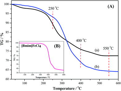
In order to investigate the correlation between structure and properties of the catalysts, various characteristics were studied. TG analysis of TiO2 and [Bmim]FeCl4/TiO2 under air atmosphere were first taken to study the calcining process of the samples. Then Am TiO2 and the catalysts calcined under different temperatures were characterized by wide-angle powder XRD, FT-IR and XPS. As shown in Fig. 1(A), when the catalyst and TiO2 were calcined at 250 °C, the weight loss of TiO2 was 3.8% more than [Bmim]FeCl4/TiO2. Since there was no obvious loss of [Bmim]FeCl4 when the temperature was below 290 °C [Fig. 1(B)], this difference of loss was caused by the decomposition of Ti(OH)4 and the desorption of water from the catalyst. As could be seen in Fig. 2, no typical diffraction was detected in the samples calcined at 250 °C [Fig. 2(a) and (b)], indicating that the synthesized TiO2 might be present in an amorphous structure. As for TiO2, the FT-IR spectra characteristic peaks around 633 cm−1, 1400 cm−1 and 1548 cm−1 were observed in Fig. 3(a). The peak at 1400 cm−1 was attributed to Ti–O bond, which came from Ti(OH)4.54 When the calcination temperatures reached 400 °C, because the [Bmim]FeCl4 decomposed violently, the difference of the loss between the two samples reached 6.9% [Fig. 1(A)]. Finally, at calcination temperature of 550 °C, the weight loss of [Bmim]FeCl4/TiO2 was 8.3% more than TiO2 [Fig. 1(A)]. The decomposition of [Bmim]FeCl4 would result in the decrease of catalytic activity in the ECODS system. As the catalysts calcined at 400 and 550 °C, diffraction peaks were observed and became stronger with the increase of calcination temperature [Fig. 2(c) and (d)]. The peaks at 25.36° (101), 38.02° (111), 48.12° (200) and 55.12° (211) were clearly representative of the anatase phase TiO2 (JSPDF no. 84-1285). As displayed in Fig. 3, the peaks at 1400 cm−1 turned weak when the calcination temperatures increased from 250 °C to 550 °C, which means that the Ti(OH)4 had broken down into TiO2 and H2O. The absorption peak of C![[double bond, length as m-dash]](https://www.rsc.org/images/entities/char_e001.gif) N in the imidazole ring was around 1591 cm−1; however, there were no evident peaks found from the curves in Fig. 3(b)–(d). That is because the peak was covered by TiO2 around 1548 cm−1. In the meantime, as shown in the Fig. 3(B) (the catalyst calcination temperatures at 250 °C), the ring stretching vibrations of the imidazole ring around 1164 cm−1 and 1107 cm−1 could be detected.55 The results proved that [Bmim]FeCl4 has been loaded onto Am TiO2 and was intact.
N in the imidazole ring was around 1591 cm−1; however, there were no evident peaks found from the curves in Fig. 3(b)–(d). That is because the peak was covered by TiO2 around 1548 cm−1. In the meantime, as shown in the Fig. 3(B) (the catalyst calcination temperatures at 250 °C), the ring stretching vibrations of the imidazole ring around 1164 cm−1 and 1107 cm−1 could be detected.55 The results proved that [Bmim]FeCl4 has been loaded onto Am TiO2 and was intact.
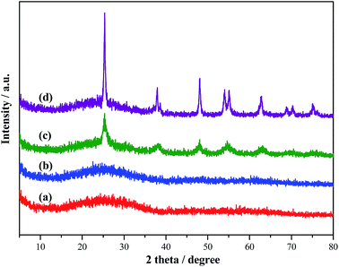 | ||
| Fig. 2 Wide angle XRD patterns at different calcination temperatures: (a) 250 °C TiO2, (b) 250 °C [Bmim]FeCl4/TiO2, (c) 400 °C [Bmim]FeCl4/TiO2 and (d) 550 °C [Bmim]FeCl4/TiO2. | ||
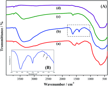 | ||
| Fig. 3 FT-IR spectra of (a) 250 °C TiO2, (b) 250 °C [Bmim]FeCl4/TiO2, (c) 400 °C [Bmim]FeCl4/TiO2 and (d) 550 °C [Bmim]FeCl4/TiO2. | ||
The XPS analysis provided further information for the evaluation of the purity and surface composition of the [Bmim]FeCl4/Am TiO2 catalyst calcined at 250 °C. The survey XPS spectrum in Fig. 4(A) demonstrated that the main elements on the surface of the catalyst were C, O, N, Cl, Ti and Fe. The C 1s peak shown in Fig. 4(B) with two peaks around at 284.9 eV and 288.5 eV could be assigned to sp2 hybridization of carbon atoms.56 As can be seen from Fig. 4(C), the N 1s peak is located at 399.8 eV, which could be ascribed to sp2-hybridized nitrogen (C![[double bond, length as m-dash]](https://www.rsc.org/images/entities/char_e001.gif) N–C).56 The high-resolution spectrum [Fig. 4(D)] showed that the peak binding energy of 529.9 eV was assigned to O 1s.54 The peak binding energy of 198.1 eV is ascribed to Cl 2p [Fig. 4(E)].57 The Ti 2p region displayed in Fig. 4(F) with characteristic peaks at 458.4 and 464.0 eV was ascribed to Ti 2p3/2 and Ti 2p1/2, respectively.54 The result of XPS further confirmed the existence of [Bmim]FeCl4 and Am TiO2 in the [Bmim]FeCl4/Am TiO2 composites, which is consistent with the result of the FT-IR analysis.
N–C).56 The high-resolution spectrum [Fig. 4(D)] showed that the peak binding energy of 529.9 eV was assigned to O 1s.54 The peak binding energy of 198.1 eV is ascribed to Cl 2p [Fig. 4(E)].57 The Ti 2p region displayed in Fig. 4(F) with characteristic peaks at 458.4 and 464.0 eV was ascribed to Ti 2p3/2 and Ti 2p1/2, respectively.54 The result of XPS further confirmed the existence of [Bmim]FeCl4 and Am TiO2 in the [Bmim]FeCl4/Am TiO2 composites, which is consistent with the result of the FT-IR analysis.
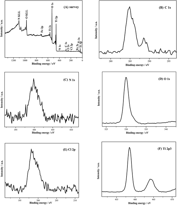 | ||
| Fig. 4 XPS spectra of [Bmim]FeCl4/Am TiO2. (A) Survey of the catalyst; (B) C 1s; (C) N 1s; (D) O 1s; (E) Cl 2p and (F) Ti 2p3. | ||
3.2 Effects of the calcination temperatures on sulfur removal
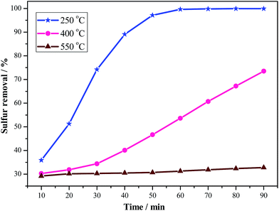
To investigate the effect of calcination temperatures of the catalysts on sulfur removal,58 three temperatures, 250 °C, 400 °C and 550 °C, were taken for [Bmim]FeCl4/TiO2. The results of various calcination temperature catalysts with different reaction times are shown in Fig. 5. The results indicated that sulfur removal decreased from 99.6% to 31.3% in 1 h with the increasing temperatures from 250 °C to 550 °C. There is no significant increase in sulfur removal when prolonging the reaction time for another 30 min. Based on the results of TG analysis (Fig. 1), [Bmim]FeCl4 remained stable at 250 °C and began to decompose at 290 °C, which means that the catalyst calcined at 250 °C and presents the highest desulfurization efficiency among the three calcination temperatures. However, as the carrier Am TiO2 transformed from the amorphous to the anatase phase at 400 and 550 °C, the defective sites on the surface were reduced, and that weakened the performance of attracting DBT. Both of the two factors resulted in the higher calcination temperatures, and the lower sulfur removal was obtained in the ECODS system. Thus, the catalyst that calcined at 250 °C and the reaction time of 1 h were chosen as the optimal conditions in the desulfurization system.3.3 Effect of different desulfurization systems on sulfur removal
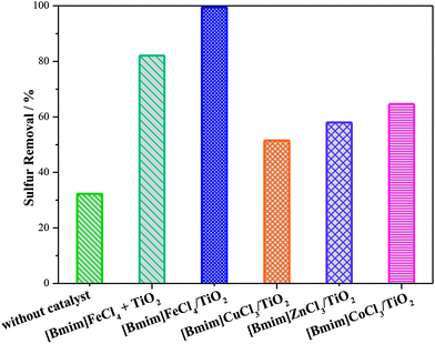
The desulfurization systems greatly affected sulfur removal,59,60 and the results of various systems containing different catalysts are shown in Fig. 6. As can be seen, sulfur removal was only 32.3% without a catalyst. Sulfur removal reached 82.1% when [Bmim]FeCl4 and Am TiO2 were employed only by simply mixing them together. When [Bmim]FeCl4 was loaded onto Am TiO2 first, and then used as catalyst in the ECODS system, sulfur removal increased evidently and reached 99.6%. These results indicated that [Bmim]FeCl4 and Am TiO2 had a synergistic effect after loading, which could improve desulfurization efficiency greatly. However, sulfur removal in desulfurization systems containing another supported ionic liquid, for example, [Bmim]CuCl3/Am TiO2, [Bmim]ZnCl3/Am TiO2 and [Bmim]CoCl3/Am TiO2, was below 65%. It is evident that [Bmim]FeCl4/Am TiO2 had the best catalytic ability among the different supported ionic liquid catalysts. Further research was focused on studying the desulfurization system catalyzed by [Bmim]FeCl4/Am TiO2.3.4 Effect of the amount of catalyst on sulfur removal
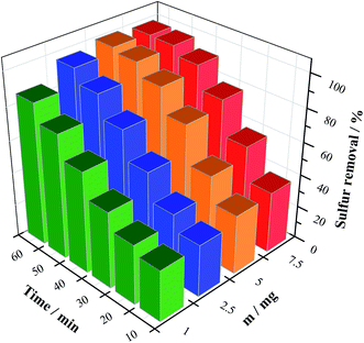
Fig. 7 shows the effect of catalyst amount on sulfur removal, and sulfur removal increased with increasing catalyst amounts. When the amount of catalyst increased from 1 mg to 5 mg, sulfur removal increased from 86.2% to 99.6% in 1 h. Compared with the previous research, this work greatly reduced the amount of [Bmim]FeCl4 required to achieve ultra-deep desulfurization.49 However, when 7.5 mg catalyst was used, sulfur removal only reached 98.4%, which is due to the possibility of [Bmim]FeCl4 increasing the decomposition of H2O2, resulting in reduced efficiency of the oxidant.37 Therefore, 5 mg catalyst was chosen as the most suitable amount in the following investigation.3.5 The effect of different reaction temperatures on sulfur removal
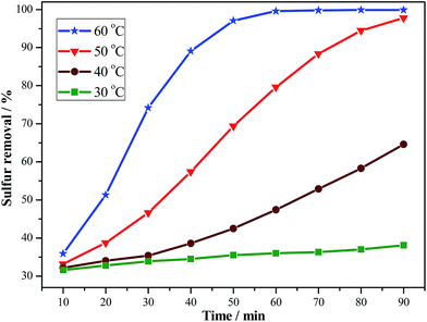
The reaction temperature is an important parameter in the desulfurization system. Sulfur removal at different reaction temperatures and time are displayed in Fig. 8. With the increase of the temperature from 40 to 60 °C, a continuous increase in the removal of DBT was observed. When the desulfurization system was reacted for 1 h, sulfur removal was 47.4%, 79.6% and 99.6% at 40, 50 and 60 °C, respectively. However, sulfur removal appeared to be unsatisfactory at 30 °C, mainly because the catalyst and oxidant cannot work efficiently at a low reaction temperature.61 Based on the abovementioned results, the reaction temperature of 60 °C was recommended.3.6 The effect of different n(H2O2)/n(DBT) on sulfur removal
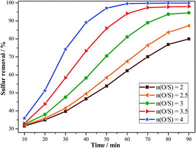
To investigate the amount of H2O2 on the removal of DBT, the desulfurization reaction was carried out under various molar ratios of H2O2 and DBT (O/S) at 60 °C. According to the stoichiometric reaction, 2 mol of H2O2 is consumed for oxidation of 1 mol DBT to DBTO2. However, as shown in Fig. 9, sulfur removal was only 62.3% when the O/S was 2 within 1 h. The reason for this was that there existed two parallel reactions in the oxidation: one was the oxidation of DBT and the other was the self-decomposition of H2O2. When the O/S increased to 4, sulfur removal reached 99.6% in 1 h. Thus, the O/S of 4 was chosen as the optimal ratio.3.7 Effects of different extractants on sulfur removal
In the ECODS system, one of the main factors was the type of extractants. To investigate the influence of different extractants on desulfurization, four conventional ILs, [Bmim]BF4, [Omim]BF4, [Bmim]PF6 and [Omim]PF6, were used in the ECODS system. [Bmim]FeCl4/Am TiO2 was insoluble in the ILs, which allowed the catalyst to be easily separated and recovered after the reaction. In addition, neither the catalyst nor the ILs could dissolve in the model oil. The results in Table 1 showed that sulfur removal in the ECODS system with the four ILs was 75.8%, 99.6%, 17.9% and 32.2%, whereas sulfur removal in the extractive desulfurization (EDS) system was 17.2%, 29.3%, 15.1% and 26.5%.61 Therefore, [Omim]BF4 was chosen as the most suitable extractant in the desulfurization experiments.| Entry | Different ILs | Sulfur removal/% | |
|---|---|---|---|
| EDSa | ECODSb | ||
a Experiment conditions: T = 60 °C, t = 1 h, VIL = 1 mL, V(model oil) = 5 mL.b Experiment conditions: m(catalyst) = 5 mg, T = 60 °C, t = 1 h, n(H2O2)/n(DBT) = 4![[thin space (1/6-em)]](https://www.rsc.org/images/entities/char_2009.gif) : :![[thin space (1/6-em)]](https://www.rsc.org/images/entities/char_2009.gif) 1, VIL = 1 mL, V(model oil) = 5 mL. 1, VIL = 1 mL, V(model oil) = 5 mL. |
|||
| 1 | [Bmim]BF4 | 17.2 | 75.8 |
| 2 | [Omim]BF4 | 29.3 | 99.6 |
| 3 | [Bmim]PF6 | 15.1 | 17.9 |
| 4 | [Omim]PF6 | 26.5 | 32.2 |
3.8 Effects of the nature of the substrates on sulfur removal
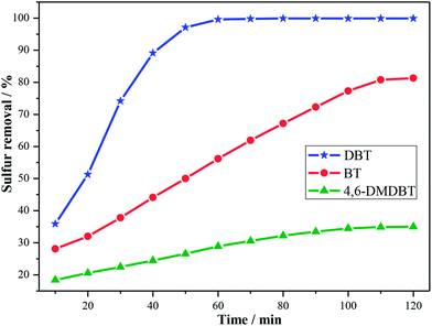
The nature of the substrates is a crucial factor influencing sulfur removal in the desulfurization system. Besides DBT, two other representatives, BT and 4,6-DMDBT, were chosen to investigate desulfurization efficiency. As shown in Fig. 10, sulfur removal decreased in the order DBT > BT > 4,6-DMDBT under the corresponding reaction conditions. Sulfur removal of DBT and BT increased over time evidently, and sulfur removal of DBT could reach deep desulfurization within 1 h, whereas sulfur removal of BT increased from 56.2% in 1 h to 81.3% in 2 h. However, what is unexpected is that the removal of 4,6-DMDBT in the desulfurization system is poor: sulfur removal was only 28.9% in 1 h and increased slightly in another hour (35%). For DBT and BT, the result could be attributed to the different electron densities of the sulfur atoms.62 The electron density of BT (5.739) is lower than DBT (5.758), which led to the low desulfurization efficiency. Though 4,6-DMDBT had the highest electron density (5.760) of the three sulfur-containing compounds, the two methyl groups on the benzene ring brought great steric hindrance, which became the main difficulty and caused the lowest sulfur removal in the ECODS system (Scheme 2).59,603.9 Recycling performance of the ECODS system
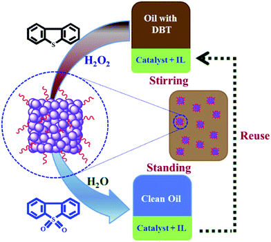
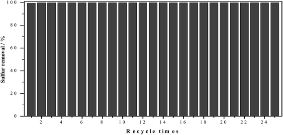
Recycling ability and multiphase reaction are two important factors in industrial applications. The recycling performance of the ECODS system was investigated on the removal of DBT in model oil. Judging from the results reported in literature,43,50,53 the stability and recycle ability of the ECODS system in this work was more outstanding than other desulfurization systems. Because the catalyst and IL were immiscible in the model oil, the model oil could be transferred easily from the system by decanting and drying, and then new model oil containing DBT was added for the next run. There was some white DBT sulfone residue in the system after oxidation. Though the amount of DBT sulfones increased over reaction times, it has no effect on the sulfur removal ability in the ECODS system. The results in Fig. 11 showed that the ECODS system had an excellent recycling performance, and the sulfur removal could still reach 100% after recycling for 25 times. This result also showed that [Bmim]FeCl4 did not leak from the carrier after the reaction, because the sulfur removal was only 82.1% when [Bmim]FeCl4 and Am TiO2 were employed by simply mixing them together (Fig. 6). Supported ionic liquid has unique advantages compared with other ionic liquid catalysts. The excellent cycling performance could promote the ECODS system applied to industrial applications of catalytic oxidative desulfurization.3.10 The proposed reaction process of ECODS system
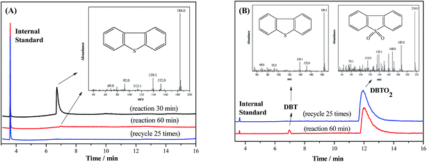
In order to research the mechanism of the ECODS system, sulfur compounds in the model oil phase and the IL phase were measured by GC-MS. During the reaction, DBT was first extracted into the ionic liquid phase from the oil phase under rigorous stirring, and then it was oxidized by H2O2 with the catalyst. After reaction, the model oil was in the upper layer, whereas the other components were in the lower layer. The model oil was withdrawn and analyzed by GC-MS directly after reaction for 30 min and 60 min, and recycled 25 times; the results are shown in Fig. 12(A). There was a strong peak belonging to DBT (m/z = 184.0)53,63 in the oil phase with sulfur removal of 74.2% after 30 min of reaction. The peak of DBT was not evident after 60 min of reaction because sulfur removal reached 99.6%. There was no DBT peak to be found in the oil phase since sulfur removal remained 100% after being recycled 25 times. The results of the IL phase are shown in Fig. 12(B). The ionic liquid phase was first re-extracted by tetrachloromethane and then detected by GC-MS. The DBTO2 peak (m/z = 216.0)53,63 could be detected in the ionic liquid phase, meaning that DBTO2 was the final oxidizing product of DBT. Based on the results mentioned above, apart from the ultra low content of DBT, there were no other sulfur-containing compounds detected in the oil phase after the reaction, meaning that clean oil was obtained after catalytic oxidative desulfurization.4. Conclusions
In conclusion, a supported ionic liquid catalyst [Bmim]FeCl4/Am TiO2 was synthesized and investigated in this work. The catalyst had high desulfurization efficiency in the removal of DBT in an ECODS system. The most appropriate conditions of catalyst calcination temperature of 250 °C, amount of catalyst 5 mg, temperature 60 °C, O/S 4, extractant 1 mL, and reaction time 1 h were obtained. GC-MS analysis was employed to detect sulfur-containing compounds after the reaction and to investigate the process of the ECODS system. The ECODS system presents an excellent recycling performance with an extremely low amount of supported ionic liquid, and the desulfurization efficiency remained 100% after recycling 25 times. Therefore, the supported ionic liquid catalyst is promising for catalytic oxidation desulfurization in industrial applications.Acknowledgements
This work was financially supported by the National Nature Science Foundation of China (no. 21276117, 21376111, 21406092), Doctoral Innovation Fund of Jiangsu Province (KYLX_1066), Six Big Talent Peak in Jiangsu province (JNHB-004) and State Key Laboratory of Heavy Oil Processing (no. SKLOP201402004).References
- J. Zhang, D. S. Zhao, L. Y. Yang and Y. B. Li, Chem. Eng. J., 2010, 156, 528–531 CrossRef CAS PubMed.
- B. B. Shao, L. Shi and X. Meng, Ind. Eng. Chem. Res., 2014, 53, 6655–6663 CrossRef CAS.
- W. L. Li, Q. F. Liu, J. M. Xing, H. S. Gao, X. C. Xiong, Y. G. Li, X. Li and H. Z. Liu, AIChE J., 2007, 53, 3263–3268 CrossRef CAS PubMed.
- Y. L. Zhang, Y. X. Yang, H. X. Han, M. Yang, L. Wang, Y. N. Zhang, Z. X. Jiang and C. Li, Appl. Catal., B, 2012, 119, 13–19 CrossRef PubMed.
- J. M. Palomino, D. T. Tran, J. L. Hauser, H. Dong and S. R. J. Oliver, J. Mater. Chem. A, 2014, 2, 14890–14895 CAS.
- J. Xiao, X. X. Wang, Y. S. Chen, M. Fujii and C. S. Song, Ind. Eng. Chem. Res., 2013, 52, 15746–15755 CrossRef CAS.
- J. Xiao, X. X. Wang, M. Fujii, Q. J. Yang and C. S. Song, AIChE J., 2013, 59, 1441–1445 CrossRef CAS PubMed.
- J. Xiong, W. S. Zhu, H. P. Li, W. J. Ding, Y. H. Chao, P. W. Wu, S. H. Xun, M. Zhang and H. M. Li, Green Chem., 2015, 17, 1647–1656 RSC.
- A. Bosmann, L. Datsevich, A. Jess, A. Lauter, C. Schmitz and P. Wasserscheid, Chem. Commun., 2001, 2494–2495 RSC.
- Y. Nie, C. X. Li, A. J. Sun, H. Meng and Z. H. Wang, Energy Fuels, 2006, 20, 2083–2087 CrossRef CAS.
- C. P. Li, D. Li, S. S. Zou, Z. Li, J. M. Yin, A. L. Wang, Y. N. Cui, Z. L. Yao and Q. Zhao, Green Chem., 2013, 15, 2793–2799 RSC.
- S. Guchhait, D. Biswas, P. Bhattacharya and R. Chowdhury, Chem. Eng. J., 2005, 112, 145–151 CrossRef CAS PubMed.
- D. Huang, Z. Zhai, Y. C. Lu, L. M. Yang and G. S. Luo, Ind. Eng. Chem. Res., 2007, 46, 1447–1451 CrossRef CAS.
- C. Komintarachat and W. Trakarnpruk, Ind. Eng. Chem. Res., 2006, 45, 1853–1856 CrossRef CAS.
- J. T. Sampanthar, H. Xiao, H. Dou, T. Y. Nah, X. Rong and W. P. Kwan, Appl. Catal., B, 2006, 63, 85–93 CrossRef CAS PubMed.
- B. Y. Zhang, Z. X. Jiang, J. Li, Y. N. Zhang, F. Lin, Y. Liu and C. Li, J. Catal., 2012, 287, 5–12 CrossRef CAS PubMed.
- Y. Lu, Y. Wang, L. D. Gao, J. C. Chen, J. P. Mao, Q. S. Xue, Y. Liu, H. H. Wu, G. H. Gao and M. Y. He, ChemSusChem, 2008, 1, 302–306 CrossRef CAS PubMed.
- J. H. Xu, S. Zhao, W. Chen, M. Wang and Y. F. Song, Chem.–Eur. J., 2012, 18, 4775–4781 CrossRef CAS PubMed.
- C. Li, Z. X. Jiang, J. B. Gao, Y. X. Yang, S. J. Wang, F. P. Tian, F. X. Sun, X. P. Sun, P. L. Ying and C. R. Han, Chem.–Eur. J., 2004, 10, 2277–2280 CrossRef CAS PubMed.
- Y. S. Chi, C. P. Li, Q. Z. Jiao, Q. S. Liu, P. F. Yan, X. M. Liu and U. Welz-Biermann, Green Chem., 2011, 13, 1224–1229 RSC.
- H. Y. Lü, J. B. Gao, Z. X. Jiang, Y. X. Yang, B. Song and C. Li, Chem. Commun., 2007, 150–152 RSC.
- W. Zhang, H. Zhang, J. Xiao, Z. X. Zhao, M. X. Yu and Z. Li, Green Chem., 2014, 16, 211–220 RSC.
- J. Wang, Q. Guo, C. Zhang and K. Li, RSC Adv., 2014, 4, 59885–59889 RSC.
- C. H. Ma, B. Dai, P. Liu, N. Zhou, A. J. Shi, L. L. Ban and H. W. Chen, J. Ind. Eng. Chem., 2014, 20, 2769–2774 CrossRef CAS PubMed.
- A. Chica, A. Corma and M. E. Domine, J. Catal., 2006, 242, 299–308 CrossRef CAS PubMed.
- F. T. Li, C. G. Kou, Z. M. Sun, Y. J. Hao, R. H. Liu and D. S. Zhao, J. Hazard. Mater., 2012, 205, 164–170 CrossRef PubMed.
- D. S. Zhao, J. L. Wang and E. Zhou, Green Chem., 2007, 9, 1219–1222 RSC.
- W. S. Zhu, C. Wang, H. P. Li, P. W. Wu, S. H. Xun, W. Jiang, Z. G. Chen, Z. Zhao and H. M. Li, Green Chem., 2015, 17, 2464–2472 RSC.
- M. Ibe, S. Gomez, K. A. Malinger, P. Fanson and S. L. Suib, Appl. Catal., B, 2007, 69, 235–239 CrossRef CAS PubMed.
- H. S. Gao, C. Guo, J. M. Xing, J. M. Zhao and H. Z. Liu, Green Chem., 2010, 12, 1220–1224 RSC.
- H. Y. Lü, S. N. Wang, C. L. Deng, W. Z. Ren and B. C. Guo, J. Hazard. Mater., 2014, 279, 220–225 CrossRef PubMed.
- J. H. Xu, S. Zhao, Y. C. Ji and Y. F. Song, Chem. Eur. J., 2013, 19, 708–714 Search PubMed.
- P. S. Kulkarni and C. A. M. Afonso, Green Chem., 2010, 12, 1139–1149 RSC.
- D. A. Vicic and W. D. Jones, J. Am. Chem. Soc., 1997, 119, 10855–10856 CrossRef CAS.
- E. Lissner, W. F. de Souza, B. Ferrera and J. Dupont, ChemSusChem, 2009, 2, 962–964 CrossRef CAS PubMed.
- F. L. Yu, Y. Y. Wang, C. Y. Liu, C. X. Xie and S. T. Yu, Chem. Eng. J., 2014, 255, 372–376 CrossRef CAS PubMed.
- J. Zhang, A. J. Wang, X. Li and X. H. Ma, J. Catal., 2011, 279, 269–275 CrossRef CAS PubMed.
- Y. Chen, S. Zhao and Y. F. Song, Appl. Catal., A, 2013, 466, 307–314 CrossRef CAS PubMed.
- H. Li, P. S. Bhadury, B. Song and S. Yang, RSC Adv., 2012, 2, 12525–12551 RSC.
- W. S. Zhu, B. L. Dai, P. W. Wu, Y. H. Chao, J. Xiong, S. H. Xun, H. P. Li and H. M. Li, ACS Sustainable Chem. Eng., 2015, 3, 186–194 CrossRef CAS.
- M. Haumann, K. Dentler, J. Joni, A. Riisager and P. Wasserscheid, Adv. Synth. Catal., 2007, 349, 425–431 CrossRef CAS PubMed.
- X. Wang, X. Zhang, H. Liu, K. L. Yeung and J. Wang, Chem. Eng. J., 2010, 156, 562–570 CrossRef CAS PubMed.
- L. Zhang, Y. D. Cui, C. P. Zhang, L. Wang, H. Wan and G. F. Guan, Ind. Eng. Chem. Res., 2012, 51, 16590–16596 CrossRef CAS.
- M. Y. Zhu, G. Q. Luo, L. H. Kang and B. Dai, RSC Adv., 2014, 4, 16769–16776 RSC.
- T. Selvam, A. Machoke and W. Schwieger, Appl. Catal., A, 2012, 445, 92–101 CrossRef PubMed.
- K. C. Goddeti, S. M. Kim, Y. K. Lee, S. H. Kim and J. Y. Park, Catal. Lett., 2014, 144, 1411–1417 CrossRef CAS PubMed.
- H. J. Zhang, X. Y. Li and G. H. Chen, J. Mater. Chem., 2009, 19, 8223–8231 RSC.
- H. H. Zhao, N. Y. Yu, Y. Ding, R. Tan, C. Liu, D. H. Yin, H. Y. Qiu and D. L. Yin, Microporous Mesoporous Mater., 2010, 136, 10–17 CrossRef CAS PubMed.
- H. M. Li, W. S. Zhu, Y. Wang, J. T. Zhang, J. D. Lu and Y. S. Yan, Green Chem., 2009, 11, 810–815 RSC.
- S. H. Xun, W. S. Zhu, D. Zheng, L. Zhang, H. Liu, S. Yin, M. Zhang and H. M. Li, Fuel, 2014, 136, 358–365 CrossRef CAS PubMed.
- U. Terranova and D. R. Bowler, J. Phys. Chem. C, 2010, 114, 6491–6495 CAS.
- G. Liu, J. A. Rodriguez, Z. Chang, J. Hrbek and L. Gonzalez, J. Phys. Chem. B, 2002, 106, 9883–9891 CrossRef CAS.
- W. S. Zhu, P. W. Wu, L. Yang, Y. H. Chang, Y. H. Chao, H. M. Li, Y. Q. Jiang, W. Jiang and S. H. Xun, Chem. Eng. J., 2013, 229, 250–256 CrossRef CAS PubMed.
- C. Wang, W. S. Zhu, Y. H. Xu, H. Xu, M. Zhang, Y. H. Chao, S. Yin, H. M. Li and J. G. Wang, Ceram. Int., 2014, 40, 11627–11635 CrossRef CAS PubMed.
- F. Wang, Z. Q. Zhang, J. Yang, L. P. Wang, Y. Lin and Y. Wei, Fuel, 2013, 107, 394–399 CrossRef CAS PubMed.
- Q. J. Xiang, J. G. Yu and M. Jaroniec, Chem. Soc. Rev., 2012, 41, 782–796 RSC.
- J. Di, J. Xia, S. Yin, H. Xu, L. Xu, Y. Xu, M. He and H. Li, RSC Adv., 2014, 4, 14281–14290 RSC.
- Z. Hasan, J. Jeon and S. H. Jhung, J. Hazard. Mater., 2012, 205, 216–221 CrossRef PubMed.
- Y. Q. Jiang, W. S. Zhu, H. M. Li, S. Yin, H. Liu and Q. J. Xie, ChemSusChem, 2011, 4, 399–403 CrossRef CAS PubMed.
- J. T. Zhang, W. S. Zhu, H. M. Li, W. Jiang, Y. Q. Jiang, W. L. Huang and Y. S. Yan, Green Chem., 2009, 11, 1801–1807 RSC.
- Y. X. Ding, W. S. Zhu, H. M. Li, W. Jiang, M. Zhang, Y. Q. Duan and Y. H. Chang, Green Chem., 2011, 13, 1210–1216 RSC.
- S. Otsuki, T. Nonaka, N. Takashima, W. H. Qian, A. Ishihara, T. Imai and T. Kabe, Energy Fuels, 2000, 14, 1232–1239 CrossRef CAS.
- W. Jiang, W. S. Zhu, Y. H. Chang, Y. H. Chao, S. Yin, H. Liu, F. X. Zhu and H. M. Li, Chem. Eng. J., 2014, 250, 48–54 CrossRef CAS PubMed.
Footnote |
| † Electronic supplementary information (ESI) available. See DOI: 10.1039/c5ra00999e |
| This journal is © The Royal Society of Chemistry 2015 |


