 Open Access Article
The effect of CO2 on the CVD synthesis of carbon nanomaterials using fly ash as a catalyst†
Nomso
Hintsho
ab,
Ahmed
Shaikjee
a,
Pranav K.
Tripathi
b,
Paul
Franklyn
ab and
Shane
Durbach
*ab
aDST-NRF Centre of Excellence in Strong Materials, University of the Witwatersrand (Wits), Private Bag X3, Johannesburg 2050, South Africa. E-mail: Shane.Durbach@wits.ac.za
bMolecular Sciences Institute, School of Chemistry, University of the Witwatersrand (Wits), Private Bag X3, Johannesburg, 2050, South Africa
First published on 2nd June 2015
Abstract
The efficient use of fly ash is a worldwide issue due to its high production and harmful effects on the environment. In this work the synthesis of carbon nanomaterials (CNMs) via the chemical vapour deposition (CVD) method, using fly ash as a catalyst and CO2 as an alternate carbon source, was investigated. Here CO2 was employed in three different ways: (1) as a sole carbon source, (2) as an additive to C2H2 and (3) as a carbon source prior to the reaction of C2H2 with fly ash. SEM, TEM and laser Raman spectroscopy confirmed that CNMs were formed in all three cases. In the first case, when CO2 was used as a sole carbon source, CNMs were formed in low yields with a considerable amount of amorphous carbon. However, in the second case when CO2 was used as an additive to C2H2, a drastic increase in CNM formation was observed. In both cases optimal yields were observed at 600 °C. However in the third case, when CO2 was used as a carbon source prior to the reaction with C2H2, uniform-sized nanofibers of the highest yields of all three cases were formed. Likewise these CNMs were found to be the most thermally stable. Hence this study has shown that the use of waste materials such as fly ash as a catalyst and CO2 as a carbon source prior to the reaction with C2H2, results in a very simple and cost efficient process to make uniformally shaped, thermally stable CNMs.
Introduction
Since the rediscovery of carbon nanomaterials (CNMs) in 1991, their production has been found to be a costly exercise. This is mainly due to the catalysts used and the carbon sources.1 In order to remediate this researchers across the world have tried to find more efficient and cheaper ways of synthesizing CNMs (e.g. carbon nanotubes (CNTs) and carbon nanofibres (CNFs)).2–5 At present, three methods are widely used for such syntheses: laser ablasion, arc-discharge and chemical vapour deposition (CVD).5–11 CVD is the most widely used of these techniques due to its high product yield, selectivity and scale-up capabilities.12 During CVD, a gas phase carbon rich molecule (e.g. C2H2) is pyrolysed in the presence of a transition metal catalyst (e.g. Fe, Mo, Cu, Co, etc.) at high temperatures (800–1000 °C).13 Though hydrocarbons are widely used, they do offer some disadvantages, as they are mostly hazardous and can form polyaromatic by-products during a CVD synthesis process.CO2 is a low energy molecule that is found in abundance on the earth.14 Due to its relative cheapness and availability, the search for uses of CO2 has attracted a lot of attention. The need to do this has been heightened by the current problems of global warming that face society and the impending shortage of fossil fuels. Recently when researchers used CO2 as an alternative carbon source for CNT production, results showed that parameters such as high pressures, specific temperature ranges, high flow rates and the choice of catalyst support played a very important role.15–18 In one study, when FeO was used on a support of CaO, CNTs were formed.14 However, when Al2O3, SiO2 and MgO were used as supports, no CNTs were produced.18 Unfortunately this approach still suffers from low CNT yields and high energy consumption due to the very high carbonization temperatures that are required. These conditions regrettably tend to be unsuitable for such approaches to be scaled up.
Recent studies have shown that an addition of a small amount of an oxygen containing species to the carbon source (e.g. C2H2) improves the yield of CNMs.19 For example, the addition of oxygen which has been shown to act as a scavenger of hydrogen radicals, has provided conditions that were suitable for CNM synthesis. On the other hand the addition of water, which acts as an etching agent that prevents the encapsulation of catalyst particles by amorphous carbon, increased the CNT yield, extended lifetime of the catalyst and an enhanced the initial growth rate as compared to those of classical C2H2 decomposition reactions.28
Fly ash is an inorganic waste material generated from the burning of coal in the production of electricity. It is an heterogeneous material with a variable composition depending on its source and the processes used. It is mainly composed of Al2O3, SiO2 and other materials such as Fe2O3, MgO and CaO.20 Disposal of this material has become a major issue due to the expense. In recent years, owing to the transition metal content in fly ash, this waste material has been at the forefront of CNM (in particular CNT/CNF) synthesis.12,13,20,21 In recent years, owing to the transition metal content in fly ash, this waste material has been at the forefront of CNM (in particular CNT/CNF) synthesis.12,13,20,21 In particular, Dunens et al. have shown that CNTs and CNFs could be synthesised by reaction of acetylene and Australian coal fly ash.13 However, unlike in this present study where no pre-treatment of the South African fly ash was required, Dunens et al. were required to further impregnate their fly ash with iron before these materials could be synthesised.13 To date, no study has reported on the use of as-received fly ash as a catalyst with CO2 as a carbon source for CNM formation. Likewise the use of fly ash, CO2 and C2H2 in one system for CNM formation has also not been reported.
This paper reports on the utilisation of two waste products, namely: fly ash and CO2 to produce CNMs. It further demonstrates the use of fly ash as a catalyst and CO2 as an additive or a as a carbon source prior to the reaction with C2H2 improved the yields of CNMs, in the CVD synthesis method.
Experimental
Synthesis
Waste South African coal fly ash was obtained from the Electricity Supply Commission (ESCOM) Research and Innovation Centre (Rosherville, South Africa) and was used without any chemical pre-treatments or thermal modifications. Carbon depositions were achieved by CVD reactions of: (1) only CO2, (2) CO2 together with C2H2 (i.e. CO2/C2H2) or (3) CO2 followed by C2H2 (i.e. CO2_C2H2) over the waste coal fly ash. An horizontal CVD furnace was used which had been fabricated in the School of Chemistry, University of the Witwatersrand, as reported previously.20 In these reactions, coal fly ash was used as a catalyst, CO2 and C2H2 were used as the carbon sources and hydrogen as the carrier gas, in order to create an optimal reaction environment.21–23 In each synthesis run, 500 mg of fly ash was uniformly spread in a quartz boat and placed in the centre of a horizontal tube furnace. The fly ash was then heated at 10°C min−1 in H2 at a flow rate of 100 ml min−1 to temperatures between 500 °C and 1000 °C. In the cases of using only CO2 or CO2 together with C2H2, these gases were introduced into the reaction zone at 100 ml min−1 for 30 min after the set temperature for reaction was reached. After 30 min of reaction time, the flows of CO2 and CO2/C2H2 were terminated and the reactor was cooled under H2 to ambient temperature. For the case where CO2 was used as carbon source prior to the reaction with C2H2, the procedure followed was the same as before except that CO2 was introduced on its own at the set reaction temperature for 30 min, then the reaction chamber was flushed out using H2 for 15 min, followed by the introduction of C2H2 into the reaction chamber for 30 min. The reactor was then cooled as before. The resultant carbonaceous material was then harvested for characterization. The percentage yield of carbon material that was formed was calculated based upon the mass of carbon obtained relative to the mass of catalyst.Characterization
The chemical composition of fly ash was determined using X-ray florescence spectroscopy (S1). The morphology and particle size of the CNMs formed from these reactions were characterized by scanning electron microscopy at an applied voltage of 10 kV using an FE-SEM ZEISS SIGMA equipped with an In-lens and secondary electron detectors and transmission electron microscopy (TEM) using a FEI Tecnai G2 Spirit electron microscope at an accelerating voltage of 120 kV. For SEM analysis, carbon tape was placed on top of a specimen holder and a small representative amount of fine powder was dusted onto the tape. The specimen then was introduced into the SEM instrument. For TEM analysis, a small amount of the powder samples of CNFs were diluted in 10 ml of ethanol, followed by sonification for 5 min. Specimens were then transferred onto the holey carbon film double layered 400 mesh copper grids (sample holder) and allowed to dry at room temperature. The specimens were then characterized by TEM.To confirm the formation of CNFs, laser Raman spectra were measured using an InVia Raman microscope (Reinshaw) at an excitation wavelength of 514 nm. Powder X-ray diffraction (PXRD) was used to identify the crystalline phases present in the ash and products using a Bruker D2 phaser with a Lynexe detector using a Co-Kα at 30 kV and 10 mA. The thermal stabilities of the products through reaction with fly ash were determined by using a Perkin Elmer Pyris 1 thermogravimetric analyser. In these measurements, 10 mg samples were heated to 900 °C at a rate of 10°C min−1 under air (20 ml min−1).
Results and discussion
A summary of the different approaches of using CO2 as well as the various outcomes (to be discussed in further detail later on) is shown in Fig. 1.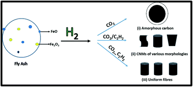 | ||
| Fig. 1 Synthesis of CNMs using CO2 as a sole carbon source, as an additive and as a carbon source prior to the reaction with C2H2. | ||
CO2 as a carbon source
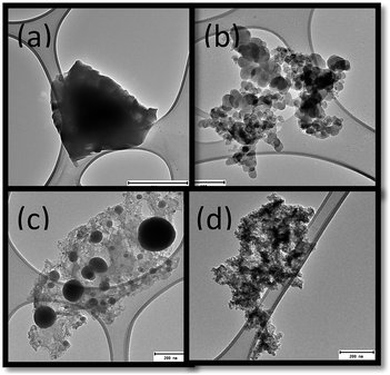
The morphologies of the products from the CO2 treated fly ash are shown in Fig. 2(a–d). These images show that various kinds of amorphous carbon had been formed. In some cases particles exhibited spherical shapes (Fig. 2(c)) and in others irregular ones (Fig. 2(d)). These differences in the amorphous carbon could possibly be due to the various mechanisms of fly ash formation or due the incomplete oxidation of the precursor coal.24The as-received fly ash and CO2 reacted fly ash were analysed by SEM (Fig. 3(a and b)). Fig. 3(a) shows the spherical shape of the as-received fly ash, while Fig. 3(b) shows the CO2 reacted fly ash. Laser Raman confirmed the presence of both amorphous and graphitic carbon, as shown by a high D (disordered) peak and a low G (graphitic) peak Fig. 3(c).25 The presence of the high D peak indicated that the carbon products that formed were poorly graphitised.16
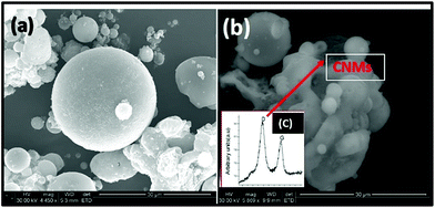 | ||
| Fig. 3 SEM images of (a) as-received fly ash, (b) carbon materials grown at 900 °C (c) laser Raman of CNMs formed at 900 °C. | ||
When as-received fly ash was used as a catalyst it was found that the very low yields of nanocarbon materials were formed at 900 °C, while at temperatures between 500–800 °C and above 1000 °C, only irregularly shaped amorphous carbon materials were formed. This is in contrast to other studies where CO2 was used as a sole carbon source and CNTs were formed.15–18 In those studies iron and cobalt were used as catalysts. The lack of CNT formation in this study could have been caused by the large quantities of Al2O3, SiO2 and MgO found in the fly ash.19,20 On the other hand, it is possible that the rate of carbon supply exceeded the growth rate of CNTs, since this has been shown to result in the formation of amorphous carbon and fibers as compared to tubes.13 Our results, in a similar manner to Xu et al.18 have revealed that the reduction of CO2 to graphitic CNMs is sensitive to both the catalyst and the temperature used. This work, together with other studies, has shown that more research is still required to understand the growth of CNMs from CO2 as a sole source of carbon.
Based on the difficulties experienced in using CO2 as a sole carbon source for CNT formation, Magrez et al.19 attempted a triple point junction reaction, where CO2, C2H2 and the FeO metal catalyst were all used in one reaction. This was done in an effort to increase the yield and favour the production of more CNTs at lower temperatures. While their study found a dramatic increase in the yield of CNTs, it was also found that this decreased at higher temperatures. In another study using Fe/MgO as a catalyst, ethanol as a carbon source and acetonitrile as a nitrogen source, a similar trend was reported.26 Here this effect was attributed to the O2 containing species which were believed to oxidise the carbon at higher temperatures. Similarly it is known that the etching effect of OH radicals disrupts the initiation stage of CNT growth.29 In this present study the reaction temperatures employed were from 500 °C to 700 °C, using as-received fly ash as a catalyst and CO2 as an additive to C2H2, which was the main carbon source.
CO2 as an additive to C2H2
When CO2 was employed as an additive to C2H2, the results obtained indicated that there was a three-fold increase in the yield in carbonaceous materials formed from 500 °C to 600 °C, which then remained constant at 700 °C. Laser Raman spectroscopy conducted on these products (Fig. 4(c)) showed that the IG/ID ratio increased as the reaction temperature was increased. This suggested that the degree of ordered carbon increased as the reaction temperature was increased.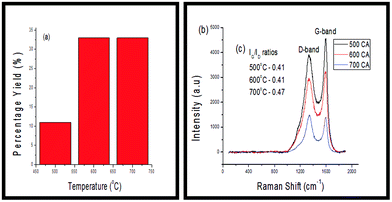 | ||
| Fig. 4 (a) Percentage yields of CNMs produced (b) Raman spectra of CNMs grown between 500–700 °C and (c) ID/IG ratios of CNMs. | ||
TGA was conducted on all of these products to test their thermal stability. As shown in Fig. 5(a), the percentage of carbonaceous products formed from the fly ash increased from 500 °C to 600 °C and then remained relatively constant at 700 °C. This trend was consistent with that of the percentage yields, as noted in Fig. 4(a).
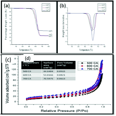 | ||
| Fig. 5 (a) TGA profile, (b) weight loss derivative, (c) adsorption isotherms and (d), Table 1: BET surface area and pore volumes of CNMs grown between 500–700 °C. | ||
Likewise the increase of the first weight derivative Fig. 5(b) to higher temperatures as the reaction temperature was increased (i.e. from ca. 600 °C to 640 °C), suggested an increase in the amounts of graphitic materials. This coincided with a corresponding decrease in the IG/ID ratio (Fig. 4(c)) and a shift from straight fibres of various diameters at 500 °C and 600 °C (Fig. 6(a–d) to straight and coiled fibres at 700 °C (Fig. 6(e–f)). Similarly, as the graphitic nature of these materials increased it was observed that their surface areas also increased (Fig. 5(c)). Based upon the adsorption/desorption data, a type III hysteresis loop was observed, which corresponded to a material with non-porous structures.
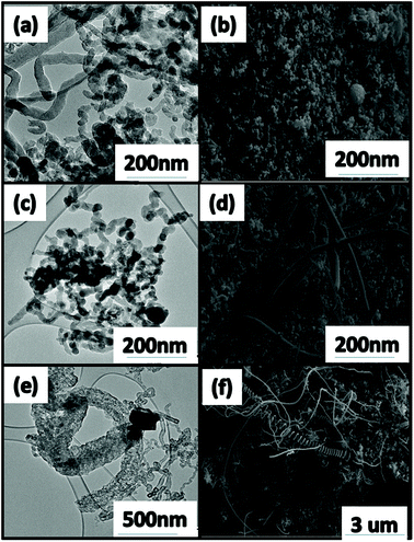 | ||
| Fig. 6 TEM and SEM images of CNF/Ts formed (a and b) 500 °C, (c and d) 600 °C and (e and f) 700 °C. The block gives the size of the scale bar. | ||
Unlike in the previous case where CO2 was used as the sole carbon source, it was noted that upon reaction between the two gases a popping noise was heard which became increasingly louder as the reaction temperature was increased. This was most likely due to the presence of the oxygen containing species (i.e. CO2) reacting with the hydrocarbon in the presence of the fly ash catalyst.27 A previous study has shown that at least two types of reactions (eqn (1) and (2)) occurred when CO2 and C2H2 were co-reacted for CNT synthesis:19
| CO2 + C2H2 → 2C + H2O + CO | (1) |
| CO2 + C2H2 → C + 2CO + H2 | (2) |
CO2 as a carbon source prior to C2H2
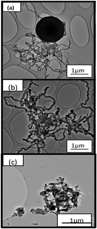
To avoid these potentially dangerous reactions from occurring, a further study was conducted where CO2 was introduced into the reaction zone on its own first. CO2 was then flushed out with H2 for 15 min. This was then followed by the introduction of C2H2. These reactions (as described previously) were also carried out in the temperature range between 500 °C to 700 °C.In Fig. 7(a), it can be observed that regularly and irregularly shaped carbon nanofibers were formed when subjected to CO2 and then C2H2. Small amounts of CNTs were also observed among the products. In Fig. 7(b) well-defined uniform CNFs, with a narrow particle size range, were observed. In Fig. 7(c), carbon nanofibers of various diameters were observed together with agglomerations of materials, which may have been caused by the sintering of the fly ash catalyst during the reaction.
As before the yields of CNMs formed revealed a slight increase at 500 °C with the use of CO2 as a carbon source prior to the reaction with C2H2 as compared to when CO2 was used as an additive. On the other hand, at 600 °C the yield increased to 49%, which was an increase of about 17% by comparison when CO2 was used as an additive with C2H2. Unlike when CO2 was used as an additive, in this case when the temperature was increased to 700 °C the percentage yield of the CNMs decreased (Fig. 8(a)). This also corresponded with an increase in the crystallinity of the fly ash from 500 °C to 700 °C as observed in Fig. 8(b). The reduction in the percentage yield may either have been caused by sintering at 700 °C or by the presence of an oxygen species (i.e. CO2) which has previously been shown to limit the growth of CNMs at higher temperatures.19
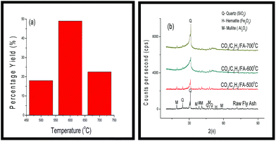 | ||
| Fig. 8 (a) Percentage yields of CNMs produced and (b) PXRD diffractograms of the raw fly ash and the CNMs that were formed from 500–700 °C. | ||
The thermal stabilities of the CNMs formed at the various temperatures are displayed in Fig. 9(a). As was the trend with the percentage yields (Fig. 8(a)), the percentage of carbonaceous products formed from the fly ash increased from 500 °C to 600 °C and then decreased at 700 °C. However, the first weight derivative (Fig. 9(b)) increased as the reaction temperature was increased, which suggested an increase in the amounts of graphitic materials. As might have been expected from the uniformity of the CNMs formed using CO2 in this way at 600 °C (Fig. 7(b)), these materials had the highest IG/ID ratio of all the materials formed in all three cases and under all three temperatures (Fig. 9(c) and (d)).
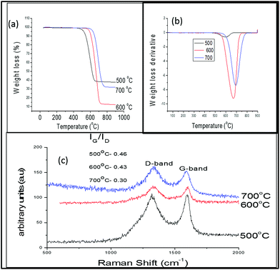 | ||
| Fig. 9 (a) Thermal decomposition (b) weight loss derivative, (c) laser Raman spectra and ID/IG ratio of CNF products from fly ash exposed to CO2 and then C2H2 at 500–700 °C. | ||
Conclusions
In this study a CVD method of producing CNMs over fly ash as a catalyst by using CO2 as a sole carbon source, an additive and a carbon source prior to the reaction with C2H2 was presented. Here it was shown that using CO2 as a sole carbon source, gave low yields and poorly formed materials, which was consistent with similar studies. When CO2 was used as either an additive or a carbon source prior to the reaction with C2H2 the yield of CNMs formed increased drastically between 500 °C and 600 °C. However, only in the case where the fly ash catalyst was pre-reacted with CO2 and then C2H2, were the highest yields of carbon nanofibers formed which were more uniformly sized and more graphitic at 600 °C. Finally, this study has shown that the use of two waste materials, fly ash and CO2 (together with C2H2) can be used to cost effectively synthesise CNMs.Acknowledgements
This work is based on the research supported in part by the National Research Foundation of South Africa (Grant number 88076), ESCOM and the DST-NRF Centre of Excellence in Strong Materials at the University of the Witwatersrand. The authors would also like to thank the Electron and Microscopy Unit (EMU) at the University of the Witwatersrand for TEM analysis.Notes and references
- S. Iijima and T. Ichihashi, Jpn. J. Appl. Phys., 1993, 32, L107–L109 CrossRef.
- P. J. Harris and P. J. Harris, Carbon nanotube science: synthesis, properties and applications, Cambridge University Press, 2009 Search PubMed.
- M. Terrones, W. K. Hsu, H. W. Kroto and D. R. Walton, in Fullerenes and related structures, Springer, 1999, pp. 189–234 Search PubMed.
- H.-S. P. Wong and D. Akinwande, Carbon nanotube and graphene device physics, Cambridge University Press, 2011 Search PubMed.
- S. Bhaviripudi, E. Mile, S. A. Steiner, A. T. Zare, M. S. Dresselhaus, A. M. Belcher and J. Kong, J. Am. Chem. Soc., 2007, 129, 1516–1517 CrossRef CAS PubMed.
- A. M. Cassell, J. A. Raymakers, J. Kong and H. Dai, J. Phys. Chem. B, 1999, 103, 6484–6492 CrossRef CAS.
- A. Peigney, P. Coquay, E. Flahaut, R. E. Vandenberghe, E. De Grave and C. Laurent, J. Phys. Chem. B, 2001, 105, 9699–9710 CrossRef CAS.
- E. Couteau, K. Hernadi, J. W. Seo, L. Thien-Nga, C. Mikó, R. Gaal and L. Forro, Chem. Phys. Lett., 2003, 378, 9–17 CrossRef CAS.
- A.-C. Dupuis, Prog. Mater. Sci., 2005, 50, 929–961 CrossRef CAS PubMed.
- S. Sharma and S. Lakkad, Surf. Coat. Technol., 2009, 203, 1329–1335 CrossRef CAS PubMed.
- M. H. Rummeli, F. Schäffel, A. Bachmatiuk, D. Adebimpe, G. Trotter, F. Borrnert, A. Scott, E. Coric, M. Sparing and B. Rellinghaus, ACS Nano, 2010, 4, 1146–1152 CrossRef CAS PubMed.
- N. Salah, S. S. Habib, Z. H. Khan, A. Memic and M. N. Nahas, Dig. J. Nanomater. Bios., 2012, 7, 1279–1288 Search PubMed.
- O. M. Dunens, K. J. MacKenzie and A. T. Harris, Environ. Sci. Technol., 2009, 43, 7889–7894 CrossRef CAS PubMed.
- G. Ordorica-Garcia, M. Nikoo, M. Carbo and I. Bolea, J. Can. Pet. Technol., 2012, 51, 362–375 CrossRef CAS.
- M. Motiei, Y. R. Hacohen, J. Calderon-Moreno and A. Gedanken, J. Am. Chem. Soc., 2001, 123, 8624–8625 CrossRef CAS.
- Z. Lou, Q. Chen, W. Wang and Y. Zhang, Carbon, 2003, 41, 3063–3067 CrossRef CAS.
- Z. Lou, C. Chen, H. Huang and D. Zhao, Diamond Relat. Mater., 2006, 15, 1540–1543 CrossRef CAS PubMed.
- X.-J. Xu and S.-M. Huang, Mater. Lett., 2007, 61, 4235–4237 CrossRef CAS PubMed.
- A. Magrez, J. W. Seo, V. L. Kuznetsov and L. Forró, Angew. Chem., Int. Ed., 2007, 119, 445–448 CrossRef PubMed.
- N. Hintsho, A. Shaikjee, H. Masenda, D. Naidoo, D. Billing, P. Franklyn and S. Durbach, Nanoscale Res. Lett., 2014, 9, 1–11 CrossRef CAS PubMed.
- Z. Yu, D. Chen, B. Tøtdal and A. Holmen, Mater. Chem. Phys., 2005, 92, 71–81 CrossRef CAS PubMed.
- A. V. Melechko, V. I. Merkulov, T. E. McKnight, M. Guillorn, K. L. Klein, D. H. Lowndes and M. L. Simpson, J. Appl. Phys., 2005, 97, 041301–041339 CrossRef PubMed.
- D. L. Plata, E. R. Meshot, C. M. Reddy, A. J. Hart and P. M. Gschwend, ACS Nano, 2010, 4, 7185–7192 CrossRef CAS PubMed.
- S. Ikeda, K. Tachi, Y. H. Ng, Y. Ikoma, T. Sakata, H. Mori, T. Harada and M. Matsumura, Chem. Mater., 2007, 19, 4335–4340 CrossRef CAS.
- S. K. Yadav, S. S. Mahapatra, H. J. Yoo and J. W. Cho, Nanoscale Res. Lett., 2011, 6, 122 CrossRef PubMed.
- P. Ayala, A. Grüneis, C. Kramberger, M. Rümmeli, I. Solorzano, F. Freire Jr and T. Pichler, J. Chem. Phys., 2007, 127, 184709 CrossRef CAS PubMed.
- G. Bepete, Z. N. Tetana, S. Lindner, M. H. Ruemmeli, Z. Chiguvare and N. J. Coville, Carbon, 2013, 52, 316–325 CrossRef CAS PubMed.
- K. Hata, T. Yamada, K. Mlzuno, M. Yumura and S. Ijima, Science, 2004, 306, 1362 CrossRef CAS PubMed.
- K. Mackenzie, O. Dunens and A. Harris, Ind. Eng. Chem. Res., 2010, 49(11), 5323–5338 CrossRef CAS.
Footnote |
| † Electronic supplementary information (ESI) available. See DOI: 10.1039/c5ra06892d |
| This journal is © The Royal Society of Chemistry 2015 |

