A series of polyoxometalate-based compounds including infinite Ag belts and circles constructed by two tolyl-1H-tetrazole isomers†
Ai-Xiang Tian*,
Xue Hou,
Jun Ying,
Guo-Cheng Liu,
Yang Yang,
Ya-Li Ning,
Tian-Jiao Li and
Xiu-Li Wang*
Department of Chemistry, Bohai University, Jinzhou, 121000, P. R. China. E-mail: tian@bhu.edu.cn; wangxiuli@bhu.edu.cn; Fax: +86-416-3400158; Tel: +86-416-3400158
First published on 29th May 2015
Abstract
In this paper, three new polyoxometalate (POM)-based metal–organic compounds containing silver cycles/belts, namely, [K2Ag15(L1)10(H2O)2][H(PMo11VIMoVO40)2] (1), [Ag7(L1)4][PW12O40]·2H2O (2) and [Ag10(L2)8(H2O)][PW12O40] (3) (L1 = 5-o-tolyl-1H-tetrazole, L2 = 5-m-tolyl-1H-tetrazole), have been obtained under hydrothermal conditions and characterized by single-crystal X-ray diffraction, IR spectra and powder X-ray diffraction (PXRD). The organic molecules L1 and L2 are isomeric. In compound 1, there exist two dimensional (2D) Ag-L1 layers including Ag belts, which are further linked by Ag5 to form a 3D metal–organic framework (MOF). The inorganic chain in 1 with Keggin anions linked by Ag1 ions insert into the channels of this 3D MOF. In compound 2, the Ag-L1 belts are connected by Keggin anions to construct a 2D layer. Adjacent layers link with each other through Ag–O bonds and the 3D framework of 2 is thus built. In compound 3, the 2D Ag-L2 layer possesses Ag cycles. Adjacent layers are linked by Ag–N bonds and Keggin anions to form the 3D structure of 3. The influence of the types of POM anions and organic ligands on the final structures was discussed. Furthermore, the electrochemical, photocatalytic and fluorescent properties of compounds 1–3 were investigated.
Introduction
It has been widely recognized that inorganic–organic hybrid complexes based on polyoxometalates (POMs) are attracting significant attentions on account of their abundant structures and potential physical and chemical properties, such as catalysis, electrochemical activity, photochemistry, material science and medicine.1 Polyoxometalates (POMs), as a unique family of metal–oxygen clusters, are made up of early transition metals like Mo, W, V, Nb and Ta in their highest oxidation states. From the synthetic point of view, POMs including abundant terminal/bridging oxygen atoms are in favour of acting as inorganic linkages to link metal–organic complexes, inducing abundant zero-dimensional (0D) to three-dimensional (3D) POM-based compounds.2 The POMs as inorganic building blocks incorporated into the complex system is not only a way to obtain high dimensional structures, but also an effective strategy to construct functional solid materials. Up to now, to the best of our knowledge, a large number of POM-based compounds have been reported, especially based on Keggin anions.3 Therefore, in order to construct more fascinating metal–organic frameworks, using Keggin POMs as inorganic linkage is a rational and effective method.On the other hand, an appropriate selection of transition metal ions and organic ligands is extremely important to construct novel structures of POM-based compounds. Among the various transition metal ions, AgI as a d10 transition metal cation shows rich coordination modes and high affinity to O- and N-donors in organic ligands, which conduces to form Ag belts and cycles assisted by ligands to modify POMs. The AgI also owns widely potential applications in the field of photochemical, catalytic, medical chemistry and so on.4 In POM-based compounds, diverse organic ligands have been used. Among these ligands, the rigid ones particularly attracted our attention owing to not only their strong coordination abilities but also their stable coordination modes, which is an essential factor for target syntheses of POM-based compounds.5 In our previous work, we choosed rigid 5-phenyl-1H-tetrazole (Hptz) to construct POM-based compounds. In this work, we try to explore whether the introduction of –CH3 substituent group to organic ligands has effect on the final structures of POM-based compounds.6 Thus, we introduced rigid organic ligands into Keggin-Ag system, namely, 5-o-tolyl-1H-tetrazole (L1) and 5-m-tolyl-1H-tetrazole (L2). Both isomeric L1 and L2 consist of a tetrazole group and a tolyl group. The tetrazole group owns four successive N atoms conducing to connect various metal ions and construct novel metal–organic subunits. Though the tolyl group has no N donors, the C atoms may also coordinate with Ag ions, which have been observed in some POM–Ag compounds.7 Furthermore, the tolyl group can provide hydrogen bonding interactions with O atoms of POMs, aiming to stabilize the structures. We also want to explore whether the different methyl site in L1 and L2 exhibit influence on the structures.8 The L1 and L2 were firstly used in the POM field. In a word, based on the aforementioned considerations, we chose Keggin-Ag-L1/L2 system in this work to build new POM-based structures.
Herein, we report the syntheses and characterizations of three new compounds in the Keggin-Ag-L1/L2 system, [K2Ag15(L1)10(H2O)2][H(PMo11VIMoVO40)2] (1), [Ag7(L1)4][PW12O40]·2H2O (2) and [Ag10(L2)8(H2O)][PW12O40] (3). Compounds 1–3 show distinct infinite Ag belts and cycles. Furthermore, we also studied the electrochemical, photocatalytic and fluorescence properties of these title compounds (Scheme 1).
 | ||
| Scheme 1 The ligands 5-o-tolyl-1H-tetrazole (L1) and 5-m-tolyl-1H-tetrazole (L2) used in this paper. | ||
Experimental
Materials and characterization
All reagents and solvents for syntheses were purchased commercially and were used as received without further purification. Elemental analyses (C, H, and N) were carried out with a Perkin-Elmer 2400 CHN elemental analyzer. The IR spectra were taken on an Alpha Centaurt FT/IR spectrometer with pressed KBr pellets in the 400–4000 cm−1 region. UV-Vis absorption spectra were obtained using a SP-1900 UV-Vis spectrophotometer. Electrochemical measurements and date collection were performed with a CHI 440 electrochemical workstation. A conventional three-electrode system was used with a saturated calomel electrode (SCE) used as a reference electrode, and a Pt wire as a counter electrode. Chemically bulk-modified carbon-paste electrodes (CPEs) were used as the working electrodes.X-ray crystallographic study
Crystallographic data for compounds 1–3 were collected with a Bruker Smart Apex CCD diffractometer with Mo-Kα (λ = 0.71073 Å) at 293 K. The structures were solved by direct methods and refined on F2 by full-matrix least squares methods using the SHELXTL package.9 For the compounds, the hydrogen atoms attached to water molecules were not located, but were included in the structure factor calculations. The detailed crystallographic data and structural determination for 1, 2 and 3 are provided in Table 1. Selected bond lengths and angles of the title compounds are given in Table S1.†| 1 | 2 | 3 | |
|---|---|---|---|
| a R1 = ∑‖Fo| − |Fc‖/∑|Fo|.b wR2 = {∑[w(Fo2 − Fc2)2]/∑[w(Fo2)2]}1/2. | |||
| Formula | C80H75Ag15K2Mo24N40O82P2 | C32H32Ag7N16O42PW12 | C64H58Ag10N32O41PW12 |
| Fw | 6969.5 | 4305 | 5247 |
| Crystal system | Triclinic | Triclinic | Monoclinic |
| Space group | P![[1 with combining macron]](https://www.rsc.org/images/entities/char_0031_0304.gif) |
P![[1 with combining macron]](https://www.rsc.org/images/entities/char_0031_0304.gif) |
P21/c |
| a (Å) | 14.554(5) | 12.083(5) | 24.980(3) |
| b (Å) | 14.649(5) | 12.283(5) | 19.327(3) |
| c (Å) | 20.459(7) | 12.941(5) | 21.407(3) |
| α (°) | 83.042(7) | 73.276(6) | 90 |
| β (°) | 77.036(7) | 76.471(7) | 96.019(2) |
| γ (°) | 64.534(6) | 86.012(7) | 90 |
| V (Å3) | 3836(2) | 1788.4(12) | 10278(2) |
| Z | 1 | 1 | 4 |
| Dc (g cm−3) | 3.015 | 3.993 | 3.390 |
| μ (mm−1) | 3.929 | 21.192 | 15.331 |
| F(000) | 3267 | 1900.0 | 9460 |
| R1a [I > 2σ(I)] | 0.0916 | 0.0442 | 0.0428 |
| wR2b (all data) | 0.2481 | 0.1117 | 0.1084 |
| GOF on F2 | 1.000 | 0.991 | 1.017 |
| Rint | 0.0829 | 0.0293 | 0.0631 |
Preparation of the title compounds
Preparations of 1-, 2- and 3-CPEs
Compound 1 modified CPE (1-CPE) was fabricated as follows: the graphite powder (0.10 g) and compound 1 (0.01 g) were mixed and ground together by an agate mortar and pestle to achieve a uniform mixture, and then was added 0.1 mL of Nujol with stirring. The homogenized mixture was packed into a glass tube with a 1.5 mm inner diameter, and the tube surface was wiped with weighing paper. Electrical contact was established with a copper rod through the back of the electrode. In a similar manner, 2- and 3-CPEs were manufactured with compounds 2 and 3.Results and discussion
Description of crystal structures
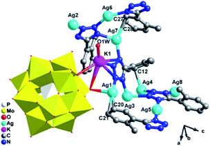 | ||
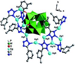
| Fig. 1 Ball/stick and polyhedral view of the asymmetric unit of 1. The hydrogen atoms are omitted for clarity. | ||
There are eight crystallographically independent Ag ions with four kinds of coordination modes: (i) the Ag1 and Ag7 ions are both adopt five-coordinated modes in a distorted bipyramidal geometry. The Ag1 is coordinated by C20, C21, N6 from two different L1 ligands, one bridging O7 and one terminal O40 atom from two PMo12 anions, while Ag7 is coordinated by two C atoms (C27 and C28) from one L1, two N atoms (N1 and N8) from two L1 ligands and one terminal O20 from one PMo12 anion. (ii) The Ag2, Ag3 and Ag6 ions are all three-coordinated in a “Y-shape” geometry. The Ag2, Ag3 and Ag6 ions are coordinated by three N atoms (N3, N4 and N17 for Ag2, N5, N20 and N11 for Ag3 and N2, N18 and N16 for Ag6) from three L1 ligands. (iii) The Ag5 ion is coordinated by two N12 atoms from two L1 ligands in a linear geometry. (iv) The Ag4 and Ag8 ions are both four-coordinated in a distorted “seesaw” geometry. The Ag4 is coordinated by N10, N15, N19 and C12 from four L1 ligangs, which Ag8 is coordinated by N14, N19 and N13 from three L1 ligands and one terminal O16 atom from one anion. Notably, there really exist Ag–C bonds in compound 1, just conform to the expectation for choosing L1 ligand, which are rarely observed in POM-based metal–organic complexes. The Ag–C bonds distances are 2.43(3) Å for Ag(1)–C(21)#3, 2.47(2) Å for Ag(1)–C(20)#3 and 2.54(2) Å for Ag(7)–C(28)#6. The PMo12 anion offers two bridging and four terminal O atoms acting as a hexa-dentate inorganic ligand to link six silver ions (Fig. S1a†). The corresponding bond lengths and angles are listed in Table S1.†
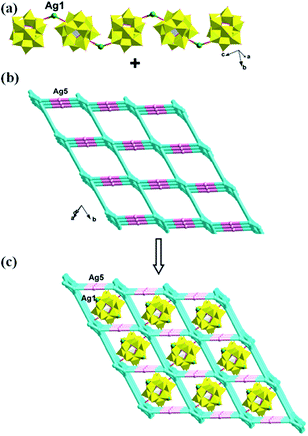
In compound 1, the Ag4, Ag6, Ag2 and Ag8 ions are connected by L1 ligands to construct an infinite Ag belts (Fig. 2a). Adjacent Ag belts are linked by Ag3, Ag7 and L1 ligands through Ag–N bonds to generate a 2D AgI-L1 network. The Ag5 ions connect adjacent networks to construct a 3D metal–organic framework (MOF) with 1D channels (Fig. 3b). Compound 1 also contains a 1D inorganic chain with Keggin anions linked by Ag1 ions (Fig. 3a). These inorganic chains insert into the 1D channels of the 3D MOF through Ag–O bonds (Fig. 3c).
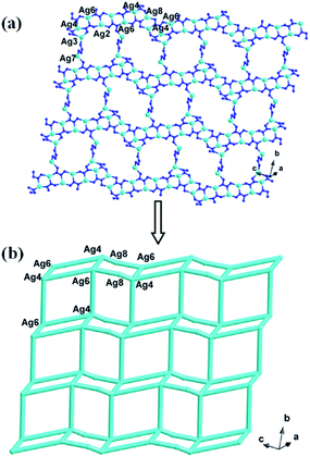 | ||
| Fig. 2 The schematic view of 2D layer constructed by infinite Ag-L1 belts (the C atoms are omitted for clarity). | ||
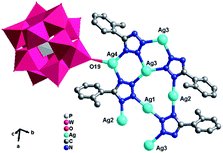 | ||
| Fig. 4 Ball/stick and polyhedral view of the asymmetric unit of 2. The hydrogen atoms and crystal water molecules are omitted for clarity. | ||
There are four crystallographically independent Ag ions showing three kinds of coordination modes: (i) the Ag1 ion is two-coordinated in a linear geometry by two N6 atoms from two L1 ligands. (ii) The Ag2 ion is in a slightly distorted T-type geometry, coordinated by N5 and N4 ions from two L1 ligands and one O atom from one water molecules. (iii) Both the Ag3, Ag4 ions are four-coordinated in a “distorted seesaw” geometry. The Ag3 ion is coordinated by three N atoms (N2, N7 and N3) from three L1 ligands and one terminal O5 atom from one PW12 anion, while the Ag4 ion is coordinated by N1 and N8 from two L1 ligands, two terminal O atoms (O19 and O14) from two PW12 anions. The distances and angles around the AgI ion are 2.127(10)–2.372(11) Å for Ag–N, 2.350(10)–2.591(10) Å for Ag–O, 102.3(3)–180.000(1)° for N–Ag–N and 80.7(4)–125.5(4)° for N–Ag–O. The corresponding bond lengths and angles are given in Table S1.†
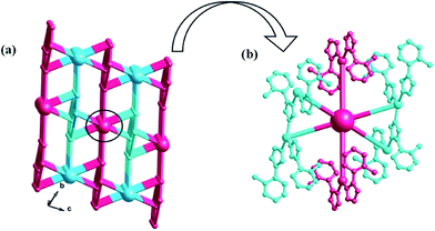
Similar to compound 1, there also exists a 1D infinite belt with L1 ligands fused by silver ions (Fig. 5a). In this AgI-L1 belt, four N donors in L1 are all utilized to link AgI ions and the tolyl- groups suspend up and down this belt. Furthermore, the PW12 anions play the role of inorganic linkers through offering two terminal O atoms to connect two adjacent AgI-L1 belts and a 2D layer of 2 is formed (Fig. 5b and c). The adjacent 2D layers are further extended into a 3D framework through sharing the same Ag–O bonds. Namely, the PW12 anion also plays an important role by providing four oxygen atoms to coordinate with silver ions from the adjacent 2D layer to form a 3D framework (Fig. 6). In a word, the PW12 anion in compound 2 acts as a hexa-connected inorganic linker coordinating with six silver ions through six terminal oxygen atoms (Fig. S1b†).
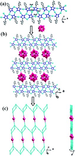 | ||
| Fig. 5 (a) View of the 1D Ag-L1 belt in 2. (b) View of the 2D layer with adjacent Ag-L1 belts linked by PW12 anions. (c) Schematic view of the 2D layer viewing along the different given directions. | ||
 | ||
| Fig. 7 Ball/stick and polyhedral view of the asymmetric unit of 3. The hydrogen atoms and crystal water molecules are omitted for clarity. | ||
There are ten crystallographically independent Ag ions exhibiting three kinds of coordination geometries: (i) all the Ag1, Ag2, Ag3, Ag5 and Ag8 adopts four-coordinated modes. The Ag1 and Ag2 ions are coordinated by three N atoms (N27, N24 and N20 for Ag1, N28, N19 and N21 for Ag2) from three different L2 ligands, one O atom from O1W. The Ag3 and Ag8 are coordinated by three N atoms (N12, N13 and N31 for Ag3, N3, N6 and N5 for Ag8) from three L2 ligands, one terminal O atom (O7 for Ag3 and O5 for Ag8) from one PW12 anion. The Ag5 is disordered to three sites as Ag5A, Ag5B and Ag5C with Ag5A half-occupied, Ag5B and Ag5C quarter-occupied. The Ag5 adopts a “distorted seesaw” geometry coordinated by N16, N17, N18 and N22 from four L2 ligands. (ii) The Ag4, Ag7, Ag9 and Ag10 all show a similar three-coordinated mode in a slightly distorted T-type geometry, coordinated by three N atoms (N11, N2 and N30 for Ag4, N4, N9 and N7 for Ag7, N32, N14 and N25 for Ag9 and N15, N23 and N26 for Ag10) from three L2 ligands. (iii) The Ag6 ion adopts a five-coordinated mode in a distorted trigonal bipyramid geometry, coordinated by three N atoms (N1, N8 and N10) from three L2 ligands and two O atoms (O8 and O9) from different PW12 anions. The PW12 anion provides five terminal O atoms to link five AgI ions (Fig. S1c†). The corresponding bond lengths and angles are listed in Table S1.†
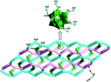
The biggest structural feature of compound 3 rests on the big AgI cycle in the 2D metal–organic layer (Fig. 8), formed by AgI ions fused by L2 ligands. The AgI-L2 cycle in 3 exhibits a dumbbell-style. Furthermore, the adjacent layers are linked each other through Ag5–N bonds to construct a 3D framework of 3. The cycles in adjacent two layers are staggered, in order to reduce the repulsion (Fig. S2†). The PW12 anion also insert into this 3D MOF covalently to further stabilize the structure of 3 (Fig. 9).
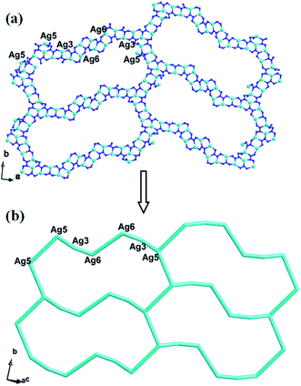 | ||
| Fig. 8 (a) The big AgI cycle in compound 3 (the C atoms are omitted for clarity). (b) Schematic view of the 2D layer. | ||
Influences of POMs and isomeric ligands on the structures of the compounds
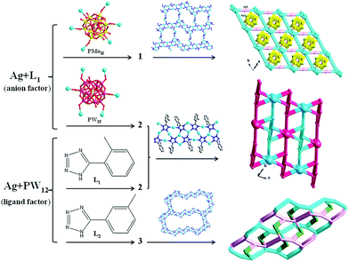
As validated by many research, in the hydrothermal process, many factors could influence the final structures, such as the type of POM anions,12 molar ratio of initial reactants,13 pH value,14 ligands15 and so on. In the Ag/L1 system, we introduced two different anions PMo12 and PW12 for construction of novel structures. Even though they have the same negative charges, the subtle differences of volume still cause the different structures of 1 and 2. In compound 1, the 1D POMs chains locate in the voids of the 3D framework containing AgI-L1 belts. The PMo12 anion in 1 offers four terminal and two bridging O atoms to link six AgI ions. In compound 2, adjacent infinite belts are fused by PW12 anions to generate a 3D framework, by providing six terminal O atoms. For the Ag/PW12/L1 system of 2, we changed L1 to L2 and different structure of 3 was synthesized under same reaction conditions. Compared with 2, the obvious structural feature of 3 rests on the big AgI cycle in the 2D metal–organic layer. Isomers of the L1 and L2 ligands may cause the influences on construction of compounds 2 and 3. This result shows that the types of anions and organic ligands can influence the final structures. Hence our work would provide more useful informative data in the rational design of target syntheses under hydrothermal conditions (Scheme 2).FT-IR spectra and powder X-ray diffraction (PXRD)
The IR spectra of compounds 1–3 are shown in Fig. S3.† In the spectrum of compound 1, characteristic bands at 1066, 964, 881 and 805 cm−1 for 1 are attributed to ν(P–O), ν(Mo–Od), and ν(Mo–Ob/c–Mo).16 In the spectra of 2 and 3, the bands at 1072, 977, 888 and 805 cm−1 for 2 and 1086, 984, 889 and 812 cm−1 for 3 are the characteristic peaks of ν(P–Oa), ν(W–Od), and ν(W–Ob/c–W), respectively.17 Furthermore, Bands in the regions of 1378–1607 cm−1 for 1, 1359–1600 cm−1 for 2, and 1417–1601 cm−1 for 3 are attributed to the L1 and L2 ligands,18 respectively (Fig. S3†). The PXRD patterns of compounds 1–3 are presented in Fig. S4.† The diffraction peaks of both simulated and experimental patterns match well in the key positions, thus showing that the phase purities of the compounds 1–3 are good.Photocatalytic property
As is known, some POM-based compounds can be used as excellent photocatalysts to degrade organic dyes.19 In this work, the photocatalytic performance of the title compounds has been investigated by the degradation of rhodamine B (RhB) solution under UV irradiation. In the typical process of photocatalysis, firstly 100 mg of compound 1, 2 or 3 were suspended in 0.02 mmol L−1 RhB aqueous solution (250 mL). The solutions were magnetically stirred to ensure the equilibrium in the dark for 10 min. Then, every 20 min 5.0 mL samples were taken out for analysis by UV-visible spectroscopy. It can be clearly observed from Fig. 10 and S5,† the absorption peaks of RhB decreased obviously with increasing of reaction time in the presence of the title compounds. The results reveal that the conversions of RhB are 64.5% for 1, 77.4% for 2 and 86.7% for 3. The results indicate that compounds 1, 2 and 3 own excellent photocatalytic activities for the degradation of RhB, especially compound 3. To the best of our knowledge, POM-based compounds with such high degradation rate for the degradation of RhB are very limited up to now. In comparison, we also explored the photocatalytic properties of the title compounds in dark environment, without UV light irradiation. The conversions of RhB are 46.2% for 1, 55.5% for 2 and 63.6% for 3 (Fig. S6 and S7†) after 100 min. This result indicates that photocatalytic effect on RhB of the title compounds in dark environment is poor compared with that under UV light irradiation. Moreover, we also investigate the photocatalytic activities of parent POM anions for decomposition of RhB under the same conditions for comparison with the title compounds. As shown in Fig. S8 and S9,† the conversions of RhB are only 12.7% for PMo12 and 13.7% for PW12, which are lower than that of the title compounds as catalysts, respectively. Therefore, the Keggin-Ag-L1/L2 systems can increase the photocatalytic activity of parent POMs to the degradation of RhB. In addition, the PXRD patterns of the compounds 1–3 after the photocatalytic reactions of RhB have been studied, which match with the simulated and experimental ones, as shown in Fig. S4.† The results suggest that the structure of compounds 1–3 remains unchanged as photocatalysts to degrade RhB contaminant.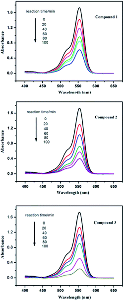 | ||
| Fig. 10 Absorption spectra of the RhB solution during the decomposition reaction under UV irradiation with the presence of compounds 1–3. | ||
Under the same condition, we also explored the photocatalytic activities of the title compounds for the degradation of methylene blue (MB) solution under UV irradiation. The conversions of MB are 71.0% for 1, 75.6% for 2 and 77.3% for 3 (Fig. S10 and S11†). This result shows that the title compounds also have good photocatalytic activities for the degradation of MB.
Cyclic voltammetry
The electrochemical properties of the 1- and 2-CPEs have been investigated here and the 2-CPE has been taken as an example to study their electrochemical properties due to the electrochemical behaviors of the 2- and 3-CPEs are similar. The cyclic voltammograms for 1- and 2-CPEs in 0.1 M H2SO4 + 0.5 M Na2SO4 aqueous solution at different scan rates are presented in Fig. 11. In the potential range of +460 to −175 mV for 1-CPE, there are three reversible redox peaks I–I′, II–II′, and III–III′. The mean peak potentials, E1/2 = (Epa + Epc)/2, are +305 (I–I′), +142 (II–II′) and −75 (III–III′) mV (scan rate: 250 mV s−1), which correspond to three consecutive two-electron processes of PMo12 anion.2b,20 For 2-CPE, three reversible redox peaks, I–I′, II–II′, and III–III′, are appear in the potential range of +120 to −780 mV. The mean peak potentials E1/2 = (Epa + Epc)/2 are −106 (I–I′), −350 (II–II′) and −670 (III–III′) mV (scan rate: 250 mV s−1). Redox peaks I–I′ and II–II′ correspond to two consecutive one-electron processes, while III–III′ corresponds to a two-electron process of PW12 anion.8 The peak potentials of cyclic voltammograms for the CPEs change gradually following the scan rates from 20 to 500 mV s−1: the cathodic peak potentials shift toward the negative direction and the corresponding anodic peak potentials to the positive direction with increasing scan rates. The peak currents are proportional to the scan rates up to 500 mV s−1 (Fig. S12†), which indicate that the redox process of the 1- and 2-CPEs are surface-confined.POMs could be used to electrocatalyze the reduction of nitrite. Fig. 12 presents the cyclic voltammograms for the electrocatalytic reduction of nitrite by the 1- and 2-CPE in 0.1 M H2SO4 + 0.5 M Na2SO4 aqueous solution. It can be distinctly seen that with addition of nitrite, all the reduction peak currents increase remarkably, while the corresponding oxidation peak currents are decreased. The results indicate that the title compounds are good potential electrocatalysts for the reduction of nitrite.
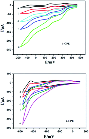 | ||
| Fig. 12 Cyclic voltammograms of the 1- and 2-CPEs in 0.1 M H2SO4 + 0.5 M Na2SO4 aqueous solution containing 0 (a); 2 (b); 4 (c); 6 (d) and 8 (e) mM NaNO2. Scan rate: 80 mV s−1. | ||
Fluorescent properties
It is well known that complexes comprising of d10 metal center and aromatic system can exhibit photoluminescence properties. In this work, the solid-state fluorescent properties of 1–3 were measured at room temperature. As shown in Fig. S13,† two prominent emission peaks are observed at about 412 and 468 nm for 1, 410 and 462 nm for 2 and 422 and 468 nm for 3 (excitation at 340 nm). The emission peak would be assigned to ligand-to-metal charge transfer (LMCT).21 These observations exhibit that compounds 1–3 with well luminescence could become candidates for potential inorganic–organic hybrid photoactive materials.Conclusions
In summary, three POM-based compounds with different structures have been synthesized through using two new isomeric ligands L1 and L2 with different occupancy site of –CH3. Under the same synthetic conditions, different anion types (PMo12 in 1 and PW12 in 2) induce distinct structures of 1 and 2, while different ligand types (L1 in 2 and L2 in 3) induce diverse frameworks of 2 and 3. This result shows that the anion types and the occupancy site of –CH3 in ligands are essential for construction of different structures of 1–3. Both 1 and 2 own Ag-L1 belts and compound 3 exists Ag-L2 dumbbell-like cycles. To explore more influencing factors for forming POM-based compounds and abundant ligands for building obvious metal–organic belts or cycles is underway.Acknowledgements
Financial supports of this research by the National Natural Science Foundation of China (no. 21101015, 21471021 and 21401010) and Program of Innovative Research Team in University of Liaoning Province (LT2012020).Notes and references
- (a) D. L. Long, E. Burkholder and L. Cronin, Chem. Soc. Rev., 2007, 36, 105 RSC; (b) A. Proust, B. Matt, R. Villanneau, G. Guillemot and G. L. P. Guozerh, Chem. Soc. Rev., 2012, 41, 7605 RSC; (c) S. Roy, CrystEngComm, 2014, 16, 4667 RSC; (d) E. Grinenval, F. Bayard, J. Basset and F. Lefebvre, Inorg. Chem., 2014, 53, 2022 CrossRef CAS PubMed; (e) A. Dolbecq, P. Mialane, B. Keita and L. Nadjo, J. Mater. Chem., 2012, 22, 24509–24521 RSC; (f) X. L. Wang, Z. H. Chang, H. Y. Lin, A. X. Tian, G. C. Liu, J. W. Zhang and D. N. Liu, RSC Adv., 2015, 5, 14020–14026 RSC; (g) X. L. Wang, C. Xu, H. Y. Lin, G. C. Liu, J. Luan and Z. H. Chang, RSC Adv., 2013, 3, 3592–3598 RSC.
- (a) X. L. Wang, J. J. Cao, G. C. Liu, A. X. Tian, J. Luan, H. Y. Lin, J. W. Zhang and N. Li, CrystEngComm, 2014, 16, 5732–5740 RSC; (b) A. X. Tian, Y. L. Ning, J. Ying, X. Hou, T. J. Li and X. L. Wang, Dalton Trans., 2015, 386–394 RSC; (c) J. Q. Sha, J. W. Sun, M. T. Li, C. Wang, G. M. Li, P. F. Yan and L. J. Sun, Dalton Trans., 2013, 1667–1677 RSC.
- (a) Q. Tang, S. X. Liu, Y. W. Liu, S. J. Li, F. J. Ma, J. X. Li, S. T. Wang and C. Z. Liu, Dalton Trans., 2013, 8512–8518 RSC; (b) A. Iturrospe, B. Artetxe, S. Reinoso, L. S. Felices, P. Vitoria, L. Lezama and J. M. G. Zorrillá, Inorg. Chem., 2013, 52, 3084–3093 CrossRef CAS PubMed; (c) H. Y. Liu, H. Wu, J. Yang, Y. Y. Liu, J. F. Ma and H. Y. Bai, Cryst. Growth Des., 2011, 11, 1786–1797 CrossRef CAS; (d) X. L. Wang, C. Qin, E. B. Wang, Z. M. Su, Y. G. Li and L. Xu, Angew. Chem., Int. Ed., 2006, 45, 7411–7414 CrossRef CAS PubMed.
- (a) X. F. Kuang, X. Y. Wu, J. Zhang and C. Z. Lu, Chem. Commun., 2011, 47, 4150–4152 RSC; (b) P. P. Zhang, J. Peng, H. J. Pang, J. Q. Sha, M. Zhu, D. D. Wang, M. G. Liu and Z. M. Su, Cryst. Growth Des., 2011, 11, 2736–2742 CrossRef CAS; (c) X. L. Wang, N. Li, A. X. Tian, J. Ying, T. J. Li, X. L. Lin, J. Luan and Y. Yang, Inorg. Chem., 2014, 53, 7118–7129 CrossRef CAS PubMed; (d) C. Streb, C. Ritchie, D. L. Long, P. Kögerler and L. Cronin, Angew. Chem., Int. Ed., 2007, 46, 1–5 CrossRef PubMed; (e) L. Yuan, C. Qin, X. L. Wang, Y. G. Lia and E. B. Wang, Dalton Trans., 2009, 4169–4175 RSC.
- (a) Z. J. Zhang, L. P. Zhang, L. Wojtas, P. Nugent, M. Eddaoudi and M. J. Zaworotko, J. Am. Chem. Soc., 2012, 134, 928–933 CrossRef CAS PubMed; (b) B. Artetxe, S. Reinoso, L. S. Felices, P. Vitoria, A. Pache, J. M. Caballero and J. M. G. Zorrillá, Inorg. Chem., 2015, 54, 241–252 CrossRef CAS PubMed; (c) A. X. Tian, X. L. Lin, J. Ying, J. W. Zhang, H. Y. Lin, G. C. Liu, D. Zhao, N. Li and X. L. Wang, Dalton Trans., 2013, 9809–9812 RSC; (d) A. X. Tian, X. Hou, N. Sun, R. Xiao, J. Ying, Y. Yang, Y. L. Ning, T. J. Li and X. L. Wang, Z. Anorg. Allg. Chem., 2014, 640, 2968–2974 CrossRef CAS PubMed.
- A. X. Tian, X. L. Lin, J. Ying, J. W. Zhang, H. Y. Lin, G. C. Liu, D. Zhao, N. Li and X. L. Wang, Dalton Trans., 2013, 9809 RSC.
- M. X. Liang, C. Z. Ruan, D. Sun, X. J. Kong, Y. P. Ren, L. S. Long, R. B. Huang and L. S. Zheng, Inorg. Chem., 2014, 53, 897–902 CrossRef CAS PubMed.
- A. X. Tian, Y. Yang, J. Ying, N. Li, X. X. Lin, J. W. Zhang and X. L. Wang, Dalton Trans., 2014, 8405–8413 RSC.
- (a) G. M. Sheldrick, SHELXS-97, 1997 Search PubMed; (b) G. M. Sheldrick, Acta Crystallogr., Sect. A: Found. Crystallogr., 2008, 64, 112 CrossRef CAS PubMed.
- H. T. Evans Jr and M. T. Pope, Inorg. Chem., 1984, 23, 501 CrossRef.
- I. D. Brown and D. Altermatt, Acta Crystallogr., Sect. B: Struct. Sci., 1985, 41, 244 CrossRef.
- X. Wang, J. Peng, M. G. Liu, D. D. Wang, C. L. Meng, Y. Li and Z. Y. Shi, CrystEngComm, 2012, 14, 3220–3226 RSC.
- L. L. Liu, C. D He, J. Li, J. B. Guo, D. Yang and J. Wei, New J. Chem., 2013, 37, 2179–2185 RSC.
- Y. N. Chi, F. Y. Cui, A. R. Jia, X. Y. Ma and C. W. Hu, CrystEngComm, 2012, 14, 3183–3188 RSC.
- Y. P. Ren, X. J. Kong, X. Y. Hu, M. Sun, L. S. Long, R. B. Huang and L. S. Zheng, Inorg. Chem., 2006, 45, 4016–4023 CrossRef CAS PubMed.
- (a) M. T. Li, J. Q. Sha, X. M. Zong, J. W. Sun, P. F. Yan, L. Li and X. N. Yang, Cryst. Growth Des., 2014, 14, 2794 CrossRef CAS; (b) J. Q. Sha, J. W. Sun, C. Wang, G. M. Li, P. F. Yan and M. T. Li, Cryst. Growth Des., 2012, 12, 2242–2250 CrossRef CAS.
- (a) H. Y. Liu, H. Wu, J. Yang, Y. Y. Liu, J. F. Ma and H. Y. Bai, Cryst. Growth Des., 2011, 11, 1786–1797 CrossRef CAS; (b) A. X. Tian, Y. Yang, N. Sun, J. Ying and X. L. Wang, J. Coord. Chem., 2014, 67, 1550–1561 CrossRef CAS PubMed.
- (a) W. C. Song, J. R. Li, C. Sañudo, J. Liu and X. H. Bu, Aust. J. Chem., 2009, 62, 941–946 CrossRef CAS; (b) A. X. Tian, X. L. Lin, N. Sun, J. Ying, J. W. Zhang, N. Li and X. L. Wang, Inorg. Chem. Commun., 2014, 40, 51–54 CrossRef CAS PubMed.
- (a) X. Meng, C. Qin, X. L. Wang, Z. M. Su, B. Li and Q. H. Yang, Dalton Trans., 2011, 9964–9966 RSC; (b) L. N. Xiao, L. M. Wang, X. N. Shan, H. Y. Guo, L. W. Fu, Y. Y. Hu, X. B. Cui, K. C. Li and J. Q. Xu, CrystEngComm, 2015, 17, 1336–1347 RSC.
- J. Q. Sha, L. Y. Liang, J. W. Sun, A. X. Tian, P. F. Yan, G. M. Li and C. Wang, Cryst. Growth Des., 2012, 12, 894–901 CAS.
- (a) X. Wang, J. Peng, K. Alimaje and Z. Y. Shi, CrystEngComm, 2012, 14, 8509–8514 RSC; (b) K. Binnemans, Chem. Rev., 2009, 109, 4283–4374 CrossRef CAS PubMed.
Footnote |
| † Electronic supplementary information (ESI) available: IR Spectra, XRD, and additional figures. CCDC 1046018–1046020. For ESI and crystallographic data in CIF or other electronic format see DOI: 10.1039/c5ra07107k |
| This journal is © The Royal Society of Chemistry 2015 |

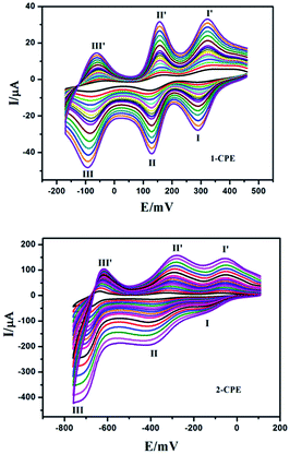
![[thin space (1/6-em)]](https://www.rsc.org/images/entities/char_2009.gif) 400, 450 and 500 mV s−1, respectively).
400, 450 and 500 mV s−1, respectively).