A polymer–metal–polymer–metal heterostructure for enhanced photocatalytic hydrogen production
Yifeng
Zhang
a,
Fang
Mao
a,
Hongjian
Yan
*b,
Kewei
Liu
b,
Hongmei
Cao
b,
Jiagang
Wu
a and
Dingquan
Xiao
*a
aCollege of Materials Science and Engineering, Sichuan University, 610064, P. R. China. E-mail: nic0402@scu.edu.cn; Fax: +86-28-85416050; Tel: +86-28-85412415
bCollege of Chemistry, Sichuan University, Chengdu, 610064, P. R. China. E-mail: hjyan@scu.edu.cn; Fax: +86 2885221339; Tel: +86 13551341892
First published on 4th November 2014
Abstract
The tightly coupled heterostructure g-C3N4/Au/poly(3-hexylthiophene) (P3HT)/Pt was successfully prepared by a self-assembling method. The heterojunction photocatalyst displayed high activity for hydrogen production from water which contains triethanolamine as an electron donor under visible light irradiation. The samples were characterized by X-ray diffraction (XRD), UV-visible spectroscopy, photoluminescence (PL) spectra analysis and transmission electron microscopy (TEM). The experimental results demonstrated that the g-C3N4/Au/P3HT/Pt structure was conducive to the efficient separation of photo-generated electron–hole pairs, which can be explained by the strong junction of chemical bond between Au and P3HT. The effect of P3HT content on the activity of the photocatalysts was investigated with a series of g-C3N4/Au/P3HT heterostructure samples loaded with Pt as a cocatalyst in triethanolamine aqueous solutions. The optimal P3HT content was determined to be 0.5 wt%, and the corresponding hydrogen evolution rate was 320 μmol h−1.
Introduction
Hydrogen is widely regarded as a potential solution to solve the energy and environment issues at a global level. The photocatalytic splitting of water plays a vital role in hydrogen production methods for the transition from a carbon-based energy system to a hydrogen-based energy system. The photocatalytic splitting of water, without electricity, directly converting sunlight into hydrogen and oxygen, will be the trump card that does not involve carbon oxide emission like the manufacture of hydrogen from fossil fuels or biological reformation of biomass. Obtaining sustainable hydrogen production to supply the amounts required needs advanced materials, synthetic technologies and new design concepts.1,2Since Fujishima and Honda found that TiO2 can cause cleavage of water under ultraviolet light,3 metal-based inorganic materials (including metal oxides, metal (oxy)nitrides, and metal oxysulfides) have occupied the field of photocatalysis with absolute dominance.4 Although these inorganic materials have led to remarkable achievements in this field, noble or rare elements are the main constituents of the metal-based complexes.5 Seeking green, sustainable and inexpensive photocatalysts made of abundant elements that we can obtain conveniently on the earth is significant for the utilization of solar energy in practical application. Therefore, organic photocatalysts for artificial photosynthesis have been developed to explore more economical and environmentally friendly methods. Recently, the polymeric organic semiconductor g-C3N4 has shown the ability of water splitting for hydrogen production under visible light.6 The utilization of polymeric organic semiconductors, which are cheap and easily available materials, opens up a new prospect to construct highly efficient and economical photocatalysis systems. However, the g-C3N4 photocatalysts suffer from many problems, such as high excitation dissociation energy, low charge mobility, low specific surface area, insufficient visible photon absorption and high level of the top of the valance band.7 In order to boost the photocatalytic efficiency of g-C3N4, several strategies, such as new synthesis methods,8–15 doping with metal or non-metal elements,16,17 dye sensitization,18,19 surface modification20–22 and construction of complexes based on g-C3N4,23–30 have been developed. These methods have proved to be effective for the promotion of the photocatalytic activity of g-C3N4.
In our previous work, the physical adsorption of poly(3-hexylthiophene) (P3HT) on the surface of g-C3N4 was achieved by evaporation of the solvent using a water bath.29 However, g-C3N4 with P3HT cannot be intimately combined because of the weak van der Waals force. This could reduce the photo-generated electron transfer efficiency between P3HT and g-C3N4. Herein, we adopted chemical bonding to ensure the tight conjunction between g-C3N4 and P3HT. Using chemical adsorption instead of physical adsorption can solve the separation problem of g-C3N4 and P3HT, and therefore we can realize the cyclic utilization of catalysts. The formation of a tight g-C3N4/Au heterojunction was obtained by the photodeposition method. In addition, 0.5 wt% Pt was loaded on the P3HT as a co-catalyst to provide chemical reactivity or active sites for H2 evolution, and improve the photocatalytic activity of catalysts.20 To the best of our knowledge, this is the first time of fabricating a polymer–metal–polymer–metal heterostructure for photocatalytic water splitting.
Experimental section
Sample preparation
Melamine, sulfuric acid (H2SO4), tetrahydrofuran (THF) and triethanolamine (TEA) were purchased from Chengdu Kelong Chemical Reagent Factory. Pluronic P123 was purchased from Aldrich. P3HT was bought from Luminescence Technology Corp. All reagents were used as received without further treatment.Preparation of g-C3N4: the g-C3N4 was synthesized via a soft-templating method by using Pluronic P123 surfactant as soft template.12 Pluronic P123 (5.0 g) and melamine (25.0 g) were dispersed in distilled water (500 mL) successively and heated at 100 °C for 1 h under magnetic stirring. Then sulfuric acid solution (10 mL, H2SO4![[thin space (1/6-em)]](https://www.rsc.org/images/entities/char_2009.gif) :
:![[thin space (1/6-em)]](https://www.rsc.org/images/entities/char_2009.gif) H2O = 1
H2O = 1![[thin space (1/6-em)]](https://www.rsc.org/images/entities/char_2009.gif) :
:![[thin space (1/6-em)]](https://www.rsc.org/images/entities/char_2009.gif) 1 v/v) was slowly added into the solution, and a white precipitate was produced. After cooling down to room temperature, the precipitate was collected by filtration. After drying in an oven at 80 °C overnight, the precipitate was heated from room temperature to 380 °C in 5 minutes and then to 600 °C at a heating rate of 1 °C min−1 and then maintained at 600 °C for 4 hours in a muffle furnace in a flow of Ar gas. After the reaction, the product was cooled down to room temperature in a flow of Ar gas. Finally, the product was then calcined at 500 °C for 2 h in air.
1 v/v) was slowly added into the solution, and a white precipitate was produced. After cooling down to room temperature, the precipitate was collected by filtration. After drying in an oven at 80 °C overnight, the precipitate was heated from room temperature to 380 °C in 5 minutes and then to 600 °C at a heating rate of 1 °C min−1 and then maintained at 600 °C for 4 hours in a muffle furnace in a flow of Ar gas. After the reaction, the product was cooled down to room temperature in a flow of Ar gas. Finally, the product was then calcined at 500 °C for 2 h in air.
The loading of 1 wt% Au on g-C3N4: g-C3N4 (1 g) was dispersed in 200 mL of 10% (v/v) TEA solution containing a certain amount of HAuCl4 solution. After evacuating the air completely, the mixture was irradiated with a Xe lamp (300 W) for 30 minutes at room temperature. After irradiation, the sample was collected by filtration and then dried at 60 °C in an oven overnight.
Preparation of g-C3N4/Au/P3HT/Pt: P3HT/Pt was prepared by a photoreduction method. Typically, chloroplatinic acid (0.5 mg), P3HT (0.5 mg) and isopropyl alcohol (0.2 mL) were dissolved in THF (16 mL). The solution was irradiated by a Xe lamp (300 W) for 30 minutes at room temperature. Then, 0.1 g g-C3N4/Au was added to the solution. The solution was stirred at room temperature for 2 hours in the dark. The slurry was filtered and washed with THF, acetone and 10% TEA sequentially. Then the photocatalyst was transferred to the reaction cell for photocatalytic reaction tests.
Photocatalytic reaction
In a typical photocatalytic experiment, the reaction was performed in a top irradiation-type Pyrex vessel connected to a glass closed gas circulation system. Photoreduction of H+ to H2 was conducted in the reaction system with an aqueous TEA solution (TEA, 10 vol%, 200 mL) as the sacrificial reagent. The light source was a 300 W xenon lamp fitted with a cutoff filter (λ > 420 nm). Prior to irradiation, the reactant solution was evacuated to remove dissolved air completely. During the reaction, a flow of cooling water was used to maintain the reactant solution at room temperature. The generated gases were detected by gas chromatography (SPSIC, GC-102AT, argon carrier).Characterization
X-ray diffraction (XRD) patterns were obtained with an X-Pert Pro diffractometer with Cu Kα radiation (λ = 1.5406 Å) at a scan step size of 0.03°. UV-visible diffuse reflection spectra were recorded with a UV-visible spectrophotometer (UV3600, Shimadzu) and converted from reflection to absorbance by the Kubelka–Munk method. BaSO4 was used as a reflectance standard in the UV-visible diffuse reflectance experiments. Photoluminescence (PL) measurements were obtained with a fluorescence spectrophotometer (Hitachi F-7000) and operated at room temperature. The excitation wavelength was 279 nm. Transmission electron microscopy (TEM) images were obtained with high-resolution transmission electron microscopy (HRTEM; JEM-2010F, JEOL). X-ray photoelectron spectroscopy (XPS) spectra were collected using a V4105 instrument (Thermo Electron, USA) with a Mn Kα radiation source.Results and discussion
Phase structures, morphology and fine structure
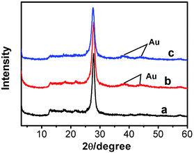
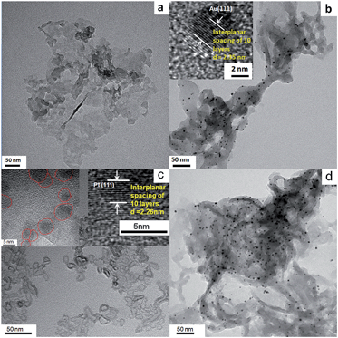
The XRD patterns of g-C3N4, g-C3N4/Au, and g-C3N4/Au/P3HT/Pt nanosheets are shown in Fig. 1. All the diffraction curves have the same diffraction peaks at 27.7° and 12.9°, corresponding to the interplanar distances of 0.322 nm and 0.682 nm, respectively. The peak at 27.7° is due to the interlayer stacking of aromatic systems, while the peak at 12.9° is related to the in-plane repeat period (e.g. the hole-to-hole distance in the nitride pores).6,15,31 The results were in good agreement with the previous reports about g-C3N4 and indicated that the main phase of g-C3N4 in the samples would not be changed by the metal loading or composite process. The diffraction peaks at 38.2° and 44.4° in the XRD patterns (see Fig. 1(b) and (c)) can be indexed to the (111) and (200) planes of Au metal particles. The diffraction peaks of both g-C3N4 and Au appeared in curves b and c, indicating that the Au was loaded on the g-C3N4 successfully. However, the diffraction peaks of P3HT and Pt were not detected in the sample of g-C3N4/Au/P3HT/Pt, because neither of their amounts was obviously high enough to form a separate phase alone.TEM was used to study the morphology and microstructures of g-C3N4, g-C3N4/Au, P3HT/Pt, and the heterostructure g-C3N4/Au/P3HT/Pt. As shown in Fig. 2(a), g-C3N4 has a layer structure and is a thin sheet with irregular morphology. Fig. 2(b) shows that the regularly shaped spherical Au nanoparticles with size of 3–5 nm were uniformly loaded on the surface of g-C3N4. The Au lattice fringes were distinctly observed as shown in the insert in Fig. 2(b). The distance of ten layers of the Au crystallites is determined as 2.35 nm (or 0.235 nm per lattice space), corresponding to the (1 1 1) crystallographic planes of cubic Au (JCPDS 04-0784). The morphology of P3HT/Pt was also investigated by TEM, as shown in Fig. 2(c). P3HT has a chain structure curled like irregular rings. The size of Pt nanoparticles is 3–5 nm as shown in the inset in Fig. 2(c). The distance of 10 layers of lattice spaces of Pt crystallite is determined as 2.26 nm (or 0.226 nm per interplanar spacing, inset in Fig. 2(c)), which matches the (1 1 1) crystallographic plane of Pt (JCPDS 04-0802). These results indicated that the two metal–polymer semiconductor heterojunction structures (g-C3N4/Au and P3HT/Pt) were indeed formed. Fig. 2(d) shows a TEM image of g-C3N4/Au/P3HT/Pt. The unobvious image contrast between g-C3N4 and P3HT may lead to us not being able to distinguish the two polymer semiconductors with TEM or even with HRTEM. Therefore, it is difficult to confirm the Au–P3HT heterostructure in g-C3N4/Au/P3HT/Pt by using TEM.
To confirm the formation of Au–P3HT heterostructure in g-C3N4/Au/P3HT/Pt, XPS was applied for elemental analysis and valence state analysis of the samples. As expected, in the sample of g-C3N4/Au/P3HT/Pt, the peak at binding energy of 163.85 eV for S 2p was observed (Fig. 3(a)). The observed sulfur signal suggested that P3HT exists in the sample of g-C3N4/Au/P3HT/Pt because of the component parts of the heterostructure only P3HT contains S element. The high-resolution Au 4f XPS spectra of g-C3N4/Au and g-C3N4/Au/P3HT/Pt are shown in Fig. 3(b). The Au 4f spectra consist of two peaks due to the electron spin. The binding energy of Au 4f5/2 and Au 4f7/2 for g-C3N4/Au was found at around 83.26 and 86.94 eV, respectively. However, the binding energy of Au 4f5/2 and Au 4f7/2 for g-C3N4/Au/P3HT/Pt was found at around 83.35 and 87.03 eV, respectively. There is about 0.09 eV shift towards high binding energy. This shift indicated the chemical state of Au loaded on the g-C3N4 changed after mixing g-C3N4/Au with P3HT/Pt. In consideration of the results of XPS, the experimental method and the Au–S bond formed between S element in the organics and Au,32,33 we speculated that P3HT/Pt was successfully integrated with g-C3N4/Au and this combination was due to the formation of Au–S bond between Au on the g-C3N4 and S in the P3HT. It is the formation of these Au–S bonds that led the Au 4f spectral peaks of g-C3N4/Au/P3HT/Pt to shift towards high binding energy.
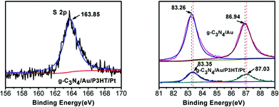 | ||
| Fig. 3 The high-resolution XPS spectra of (a) S 2p for g-C3N4/Au/P3HT/Pt and (b) Au 4f for g-C3N4/Au and g-C3N4/Au/P3HT/Pt. | ||
Optical properties of g-C3N4/Au/P3HT/Pt
The UV-visible diffuse reflectance spectra of g-C3N4, g-C3N4/Au, and g-C3N4/Au/P3HT/Pt are shown in Fig. 4. The strong absorption bands of all these photocatalysts are at wavelengths shorter than 400 nm, implying less of a condensation degree of g-C3N4. The weak tailed absorption band at 400–700 nm observed in the g-C3N4 spectrum is due to the incorporation of carbon into the melon-based carbon nitride structures.12 The absorption intensity of the g-C3N4/Au and g-C3N4/Au/P3HT/Pt photocatalysts increases noticeably in the whole measured wavelength range. The absorption band around 530 nm is due to the surface plasmon resonance (SPR) of metallic Au nanoparticles.20,22 For the sample of g-C3N4/Au/P3HT/Pt, the intensity of the absorption band around 530 nm increased further, indicating that combining g-C3N4/Au with P3HT/Pt enhanced the SPR effect of Au particles. These results further confirm the formation of conjunction between P3HT and Au.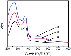 | ||
| Fig. 4 UV-visible diffuse reflectance spectra (DRS) of (a) g-C3N4, (b) g-C3N4/Au, and (c) g-C3N4/Au/P3HT/Pt. | ||
PL spectral analysis was used to study the transfer and recombination processes of photogenerated electron–hole pairs in the photocatalysts. Fig. 5 shows the PL spectra of pure g-C3N4, g-C3N4/Au and g-C3N4/Au/P3HT/Pt under incident light with a wavelength of 279 nm. All PL spectra of the samples have the same major peak at 457 nm, which could be attributed to the recombination of photoexcited electron–hole in g-C3N4 with a band gap at 2.7 eV. Significant PL quenching was observed in g-C3N4/Au and g-C3N4/Au/P3HT/Pt. The quenching of g-C3N4/Au could be attributed to electron migration from g-C3N4 to the Au particles, which was more conducive to the photoreduction of H+ to H2. Compared to g-C3N4, nearly 75% PL quenching was observed in the sample of g-C3N4/Au/P3HT/Pt, indicating that the g-C3N4/Au/P3HT/Pt photocatalyst has a lower recombination of the photogenerated electron–hole pairs and more efficient charge transfer between g-C3N4 and P3HT due to the tight conjunction between them.
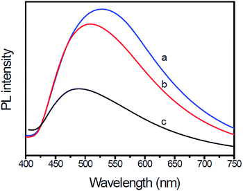 | ||
| Fig. 5 Photoluminescence (PL) emission spectra of (a) g-C3N4, (b) Au-loaded g-C3N4, and (c) g-C3N4/Au/P3HT/Pt heterostructure. The excitation wavelength was 279 nm. | ||
Photocatalytic activity and photocatalytic mechanism
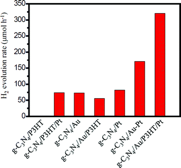
Photocatalytic H2 production was evaluated under visible light irradiation (λ > 420 nm) using TEA as sacrificial reagent. Fig. 6 shows the H2 evolution rate for different g-C3N4-based photocatalysts. As shown in Fig. 6, the g-C3N4/P3HT photocatalyst shows a negligible H2 evolution rate. However, after loading of Pt on P3HT, the H2 evolution rate of g-C3N4/P3HT/Pt reaches 74 μmol h−1. This enhanced photocatalytic H2 evolution rate could be ascribed to the efficient separation of the photogenerated electron–hole pairs in g-C3N4/P3HT/Pt photocatalyst and the platinum on the P3HT acts as an electron outlet or active site for the reduction of H+. The photocatalytic H2 evolution rate on g-C3N4/Au and g-C3N4/Pt is 73 μmol h−1 and 82 μmol h−1, respectively. Loading both Au and Pt on g-C3N4 can enhance the photocatalytic performance further. The photocatalytic H2 evolution rate on g-C3N4/Au–Pt is 171 μmol h−1, approximately the sum of H2 evolution rate on g-C3N4/Au and g-C3N4/Pt. These results also indicated that Au on g-C3N4 played a similar role to Pt as the electron outlet or active site. It is well known that the more electrons on the active site of Au surface (e.g. g-C3N4/Au) or the active site of Pt surface (e.g. g-C3N4/Pt or g-C3N4/Au/P3HT/Pt), the more conducive to H2 generation. Compared to the H2 evolution rate of g-C3N4/Au, the H2 evolution rate of g-C3N4/Au/P3HT decreased from 73 μmol h−1 to 56 μmol h−1. This indicated that, after the combination of P3HT with g-C3N4/Au, the Au surface did not gain more effective electrons for H2 evolution and the excited P3HT would not supply the electrons to the Au surface directly for H2 evolution or transfer excited electrons to g-C3N4 then to the Au surface for H2 evolution. The result reflected the fact that the combination of P3HT led the electrons on the Au surface to be efficiently consumed, which indicated that P3HT “grabbed” the electrons on the Au surface through the way that provides holes to the Au surface. The H2 evolution rate of g-C3N4/Au/P3HT/Pt is 320 μmol h−1, more than four times higher than that of g-C3N4/P3HT/Pt, g-C3N4/Au or g-C3N4/Pt. It is worth noting that the photocatalytic H2 evolution rate of g-C3N4/Au/P3HT/Pt is more than two times higher than that of g-C3N4/Au–Pt. In this case, the P3HT can be compared to an “electric wire” which transferred the elections to the far end (the realization of separating electron–hole pairs) where Pt used them for H2 generation. These results indicate that, in the heterostructure of g-C3N4/Au/P3HT/Pt, the combination of electrons on the Au surface with the holes from the HOMO of P3HT was favourable for preventing the recombination of electron–hole pairs in the body of g-C3N4 and P3HT. Therefore, Pt could obtain more electrons for H2 evolution and g-C3N4 could retain more holes for the oxidation of TEA.Fig. 7 shows the H2 evolution rate on g-C3N4/Au/P3HT/Pt with different amounts of P3HT. As shown in Fig. 7, with an increase of the amount of P3HT, the photocatalytic H2 evolution rate increases first and reaches a maximum of 320 μmol h−1 when the amount of P3HT is about 0.5 wt%. However, further increasing the amount of P3HT leads to a decrease of the photocatalytic H2 evolution.
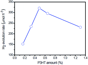 | ||
| Fig. 7 The rate of H2 evolution on g-C3N4/Au/P3HT/Pt polymer composites with different amounts of P3HT under visible light (λ > 420 nm). | ||
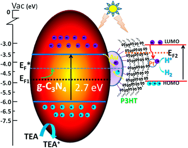
The mechanism of photocatalysis is shown in Scheme 1. Here we apply the metal–semiconductor contact theory and the Fermi level equilibration principle involving the Schottky–Mott limit demonstrated by Tang and Slyke34 and the metal–organic interface proposed by Kahn et al.35 to explain the photocatalysis mechanism of g-C3N4/Au/P3HT/Pt. The charge distribution leads to Fermi level equilibration in the metal–semiconductor system, so we can assume a quasi-Fermi level (E*F) in g-C3N4/Au/P3HT/Pt. The property of storing electrons in a quantized fashion in Au nanoparticles36,37 leads to the shift of the Fermi level of Au towards more negative potential. This may result in the Fermi level of the composite shifting closer to the conduction band of the semiconductor in the ZnO/Au system or TiO2/Au system.38,39 In the g-C3N4/Au system, the upward shift of the Fermi level (EF) of the composite to the quasi-Fermi level (E*F) in Scheme 1 has been used for reference and the photocatalytic performance of g-C3N4 improves due to the efficiency of interfacial charge-transfer process.20
On the other hand, the high work function of Au leads to small hole injection barriers (HIBs) at the metal–organic interface and it often was chosen as an electrode for hole injection.40 The HIB is defined as the energy difference between the metal Fermi level (EF) and the hole transport level in the organic semiconductor. In this scheme, the highest occupied molecular orbital (HOMO) can be regarded as the hole transport level in P3HT. However, contaminated Au surface work function values spanned the range between 4.7 and 5.1 eV and may even be larger when considering different environments.41 The HOMO of P3HT (π-conjugated polymer) was determined as 5.1 eV or 4.9 eV (bulk42,43), 4.3 eV (film44), 4.0 eV (a single strand45). If we neglect the effect of interface dipoles (IDs), admitting that the Au–S bond was indeed formed between Au and P3HT, the values of Au surface work function and the HOMO of P3HT were so close that the HIB of the interface between the P3HT and Au was very low and even forms an ohmic contact.46 The low potential barrier or ohmic contact of P3HT/Au favors charge carrier injection into each other. The holes, which transport through the P3HT network (good hole-transport material),47 will be collected at the Au surface.
In our research, however, the formation of the Au–S bond was confirmed by XPS. Therefore, the energy level alignment in reactive interfaces is controlled by chemistry-induced electronic states.37 The chemical reaction to form Au–S bonds leads to the formation of gap states and pinning of EF at the interface. Just consider the interface of P3HT/Au: if the Au work function falls in the P3HT gap, the gap states pinning EF2 lie in the upper part of the gap and increase the HIB,48 while the contaminated Au has a larger work function, and the large surface dipole of Au work function also leads to a large interface dipole barrier.35 The large HIB results in low hole transfer and reduces the photocatalytic efficiency. The HIB of P3HT/Au was determined as 0.59 eV (ref. 49) or even smaller at 0.35 eV,40 because of the different preparative approaches or the presence of ambient contamination at the Au interfaces.41
Naturally, the interface charge-transfer of g-C3N4/Au and the chemical bond of P3HT/Au or other unforeseen mechanisms, like molecule-induced modification of the metal work function, contribute to the IDs and affect each other. This becomes more complex and difficult to differentiate between the various contributions.35
In our experiment, by comparing the rate of photocatalytic H2 evolution on g-C3N4/Au and g-C3N4/Au/P3HT, it is concluded that the effective electrons on the Au surface were consumed and that the P3HT “grabbed” the electrons on the Au surface through the way that provides holes to Au surface. This means the interface of P3HT/Au realized hole transport from P3HT to the Au surface. This led us to suspect a low potential barrier had been formed at the P3HT/Au interface for the injection of charge carriers into each other. The recombination of electrons generated in g-C3N4 with the holes from the HOMO level of P3HT on the Au nanoparticle surface promoted the efficient dissociation of electron–hole pairs generated in the two kinds of polymer semiconductors. The excited electrons in P3HT transferred to the Pt and achieved the reduction of H+ to H2. The g-C3N4 got the compensation of electrons through the oxidation of TEA to TEA+. The recombination process of electrons and holes on the Au surface and the dissociation process of photo-generated electron–hole pairs in g-C3N4 and P3HT greatly enhanced the overall photocatalytic efficiency. The platinum metal introduced an ohmic contact that provided a quick transfer of electrons to the electrolyte.38 This resulted in the Fermi energy of Pt remaining close to the solution redox level and had a negligible effect on the Fermi level of the semiconductor.
Conclusions
In summary, the tightly coupled heterostructure g-C3N4/Au/P3HT/Pt was successfully prepared. Au and Pt nanoparticles with size of 3–5 nm were uniformly loaded on g-C3N4 and P3HT, respectively. The XPS result indicates the formation of Au–S bonds in g-C3N4/Au/P3HT/Pt photocatalyst. The marked PL quenching of g-C3N4/Au/P3HT/Pt photocatalyst indicates less recombination of the photogenerated electron–hole pairs. The as-prepared g-C3N4/Au/P3HT/Pt heterojunction promoted the transfer of light-excited electrons from g-C3N4 to P3HT effectively and enhanced photocatalytic hydrogen production under visible light. The g-C3N4/Au/P3HT/Pt with an amount of P3HT of 0.5 wt% achieves the highest H2 evolution rate, the photocatalytic H2 evolution rate reaching 320 μmol h−1.Acknowledgements
We thank the National Natural Science Foundation of China (no. 21273157) for financial support. We thank Sichuan University Analytical & Testing Centre for the analysis of PL and XRD, and especially Dr S. L. Wang and Dr G. P. Yuan for TEM measurements.Notes and references
- P. P. Edwards, V. L. Kuznetsov and W. I. F. David, Philos. Trans. R. Soc., A, 2007, 365, 1043 CrossRef CAS PubMed.
- J. A. Turner, Science, 2004, 305, 972 CrossRef CAS PubMed.
- A. Fujishima and K. Honda, Nature, 1972, 238, 37 CrossRef CAS.
- K. Maeda, X. C. Wang, Y. Nishihara, D. L. Lu, M. Antonietti and K. Domen, J. Phys. Chem. C, 2009, 113, 4940 CAS.
- K. Maeda and K. Domen, J. Phys. Chem. C, 2007, 111, 7851 CAS.
- X. C. Wang, K. Maeda, A. Thomas, K. Takanabe, G. Xin, J. M. Carlsson, K. Domen and M. Antonietti, Nat. Mater., 2009, 8, 76 CrossRef CAS PubMed.
- J. S. Zhang, J. H. Sun, K. Maeda, K. Domen, P. Liu, M. Antonietti, X. Z. Fu and X. C. Wang, Energy Environ. Sci., 2011, 4, 675 CAS.
- X. C. Wang, K. Maeda, X. F. Chen, K. Takanabe, K. Domen, Y. D. Hou, X. Z. Fu and M. Antonietti, J. Am. Chem. Soc., 2009, 131, 1680 CrossRef CAS PubMed.
- J. H. Liu, T. K. Zhang, Z. C. Wang, G. Dawson and W. Chen, J. Mater. Chem., 2011, 21, 14398 RSC.
- T. Tyborski, C. Merschjann, S. Orthmann, F. Yang, M.-C. Lux-Steiner and T. Schedel-Niedrig, J. Phys.: Condens. Matter, 2012, 24, 162201 CrossRef CAS PubMed.
- H. J. Yan, Y. Chen and S. M. Xu, Int. J. Hydrogen Energy, 2012, 37, 125 CrossRef CAS PubMed.
- H. J. Yan, Chem. Commun., 2012, 48, 3430 RSC.
- G. Xin and Y. L. Meng, J. Chem., 2013, 187912 Search PubMed.
- Y. Ham, K. Maeda, D. Cha, K. Takanabe and K. Domen, Chem.–Asian J., 2013, 8, 218 CrossRef CAS PubMed.
- S. Martha, A. Nashim and K. M. Parida, J. Mater. Chem. A, 2013, 1, 7816 CAS.
- G. Liu, P. Niu, C. H. Sun, S. C. Smith, Z. G. Chen, G. Q. Lu and H. M. Cheng, J. Am. Chem. Soc., 2010, 132, 11642 CrossRef CAS PubMed.
- B. Yue, Q. Y. Li, H. Iwai, T. Kako and J. H. Ye, Sci. Technol. Adv. Mater., 2011, 12, 034401 CrossRef.
- K. Takanabe, K. Kamata, X. C. Wang, M. Antonietti, J. Kubota and K. Domen, Phys. Chem. Chem. Phys., 2010, 12, 13020 RSC.
- S. X. Min and G. X. Lu, J. Phys. Chem. C, 2012, 116, 19644 CAS.
- D. Yan, X. C. Wang, A. Thomas and M. Antonietti, ChemCatChem, 2010, 2, 834 CrossRef.
- J. H. Liu, Y. W. Zhang, L. H. Lu, G. Wu and W. Chen, Chem. Commun., 2012, 48, 8826 RSC.
- S. Samanta, S. Martha and K. Parida, ChemCatChem, 2014, 6, 1453 CAS.
- M. Bledowski, L. Wang, A. Ramakrishnan, O. Khavryuchenko, V. Khavryuchenko, P. Ricci, J. Strunk, T. Cremer, C. Kolbeck and R. Beranek, Phys. Chem. Chem. Phys., 2011, 13, 21511 RSC.
- D. Mitoraj, R. Beranek and H. Kisch, Photochem. Photobiol. Sci., 2010, 9, 31 CAS.
- X. X. Xu, G. Liu, C. Randorn and J. T. S. Irvine, Int. J. Hydrogen Energy, 2011, 36, 13501 CrossRef CAS PubMed.
- H. W. Kang, S. N. Lim, D. S. Song and S. B. Park, Int. J. Hydrogen Energy, 2012, 37, 11602 CrossRef CAS PubMed.
- F. Yang, M. Lublow, S. Orthmann, C. Merschjann, T. Tyborski, M. Rusu, S. Kubala, A. Thomas, R. Arrigo, M. Hävecker and M. Schedel-Niedrig, ChemSusChem, 2012, 5, 1227 CrossRef CAS PubMed.
- L. Ge and C. C. Han, Appl. Catal., B, 2012, 117, 268 CrossRef PubMed.
- H. J. Yan and Y. Huang, Chem. Commun., 2011, 47, 4168 RSC.
- J. S. Zhang, M. W. Zhang, R. Q. Sun and X. C. Wang, Angew. Chem., Int. Ed., 2012, 51, 10145 CrossRef CAS PubMed.
- S. C. Yan, Z. S. Li and Z. G. Zou, Langmuir, 2009, 25, 10397 CrossRef CAS PubMed.
- L. J. Wang, G. M. Rangger, Z. Y. Ma, Q. K. Li, Z. G. Shuai, E. Zojer and G. Heimel, Phys. Chem. Chem. Phys., 2010, 12, 4287 RSC.
- F. Tielens and E. Santos, J. Phys. Chem. C, 2010, 114, 9444 CAS.
- C. W. Tang and S. A. Slyke, Appl. Phys. Lett., 1987, 51, 913 CrossRef CAS PubMed.
- A. Kahn, N. Koch and W. Y. Gao, J. Polym. Sci., Part B: Polym. Phys., 2003, 41, 2529 CrossRef CAS.
- S. W. Chen and R. W. Murray, J. Phys. Chem. B, 1999, 103, 9996 CrossRef CAS.
- S. Chen, R. S. Ingram, M. J. Hostetler, J. J. Pietron, R. W. Murray, T. G. Schaaff, J. T. Khoury, M. M. Alvarez and R. L. Whetten, Science, 1998, 280, 2098 CrossRef CAS.
- A. Wood, M. Giersig and P. Mulvaney, J. Phys. Chem. B, 2001, 105, 8810 CrossRef CAS.
- V. Subramanian, E. E. Wolf and P. V. Kamat, J. Am. Chem. Soc., 2004, 126, 4943 CrossRef CAS PubMed.
- S. Rentenberger, A. Vollmer, E. Zojer, R. Schennach and N. Koch, J. Appl. Phys., 2006, 100, 053701 CrossRef PubMed.
- A. Wan, J. Hwang, F. Amy and A. Kahn, Org. Electron., 2005, 6, 47 CrossRef CAS PubMed.
- M. C. Scharber, D. Mühlbacher, M. Koppe, P. Denk, C. Waldauf, A. J. Heeger and C. J. Brabec, Adv. Mater., 2006, 18, 789 CrossRef CAS.
- V. Shrotriya, G. Li, Y. Yao, C. W. Chu and Y. Yang, Appl. Phys. Lett., 2006, 88, 073508 CrossRef PubMed.
- R. P. Mikalo and D. Schmeißer, Synth. Met., 2002, 127, 273 CrossRef CAS.
- Y. Kanai and J. C. Grossman, Nano Lett., 2008, 8, 908 CrossRef CAS PubMed.
- C. H. Lei, A. Dasa, M. Elliott, J. E. Macdonald and M. L. Turner, Synth. Met., 2004, 145, 217 CrossRef CAS PubMed.
- W. U. Huynh, J. J. Dittmer and A. Paul Alivisatos, Science, 2002, 295, 2425 CrossRef CAS PubMed.
- Y. D. Park, J. H. Cho, D. H. Kim, Y. S. Jang, H. S. Lee, K. W. Ihm, T. H. Kang and K. W. Cho, Electrochem. Solid-State Lett., 2006, 9, G317–G319 CrossRef CAS PubMed.
- J. E. Lyon, A. J. Cascio, M. M. Beerbom, R. Schlaf, Y. Zhu and S. A. Jenekhe, Appl. Phys. Lett., 2006, 88, 222109 CrossRef PubMed.
| This journal is © The Royal Society of Chemistry 2015 |

