Carambola-shaped LiFePO4/C nanocomposites: directing synthesis and enhanced Li storage properties†
Xueliang
Li
*a,
Hongchang
Jin
a,
Shuai
Liu
a,
Sen
Xin
a,
Yu
Meng
a and
Jiejie
Chen
b
aSchool of Chemistry and Chemical Engineering, Hefei University of Technology, Hefei 230009, PR China. E-mail: xueliangli2005@163.com
bDepartment of Chemistry, University of Science and Technology of China, Hefei 230026, PR China
First published on 22nd September 2014
Abstract
Carbon-coated carambola-like LiFePO4, which consists of LiFePO4 thin layers with a selectively exposed (020) plane, was synthesized by a new method via oriented growth using cholesteric benzoate as a structure-directing agent. The composite exhibits stable and extremely fast kinetics upon Li storage.
Lithium-ion batteries (LIBs) have been regarded as one of the most promising solutions for emerging transportation applications including electric vehicles (EVs) and hybrid electric vehicles (HEVs).1–4 To meet the demands on vehicle endurance and service life, batteries are often required to have high theoretical capacities and long life span. In either case, LIBs based on the olivine LiFePO4 (LFP) cathode could yield satisfactory results due to a large capacity and favorable cyclability of LFP,5,6 with its low price and environmental friendliness adding to the cost effectiveness of the battery.7–10 However, with a rising demand on the power density of the battery, the use of LFP-based LIBs is hindered by their poor electrochemical reaction kinetics due to intrinsically low Li-ion diffusivity (∼1.8 × 10⁻¹⁴ cm2 s−1) and electronic conductivity of LFP.7,11–14
The combination with conductive carbon has been proved to be effective in solving the insulating problem of LFP,15–19 yet has a limited effect in improving its Li+ diffusivity. Reduction of particle size is a common way to enhance the Li+ mobility due to its role in shortening the Li+ migration pathway,20,21 however, it is not fully applicable to LFP. The reason lies in the crystal structure of olivine LFP, which allows a preferential Li migration along the [010]Pnma channel.22 Therefore, only decreasing the length of the [010] pathway can effectively enhance the Li+ mobility of LFP.
Based on this concept, LFP with a selectively exposed (020) plane and short [010] channel is especially promising, yet its synthesis is still challenging. In this paper, a novel directing synthesis procedure has been designed for LFP, which employs a cholesteric liquid crystal, cholesteryl benzoate (CB), as the structure directing agent to achieve the oriented growth of LFP along the designated direction. A carambola-like LFP (c-LFP) is prepared, which consists of LFP thin layers with a significantly shortened [010] channel of ∼15 nm and a selectively exposed (020) plane. The unique structure greatly promotes the Li+ diffusion along the preferential direction for Li storage, bringing an unprecedented Li+ diffusion coefficient of 8.31 × 10⁻⁹ cm2 s−1, which is five orders of magnitude larger than that with the bulk LFP. On the other hand, we have successfully coated a highly-conductive ultrathin carbon layer with controllable thickness (∼1.5 nm) onto the surface of LiFePO4 sheets, enabling fast electron transportation along the two-dimensional sheet. With the structural advantages of both components, a hierarchically mixed conductive network is formed, which triggers fast electrode kinetics by enabling bidirectional efficient transmissions of both Li+ and e−. The composite exhibits stable and extremely fast electrochemistry upon Li storage by delivering almost a theoretical capacity (167 mA h g−1) at 0.1 C and ∼50% of the theoretical capacity (82 mA h g−1) at a high rate of 20 C, and maintains stable cycling performances at different rates. All these promise its use in constructing batteries with stable electrochemistry and high energy output to benefit the emerging EV industry.
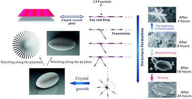
The preparation of carambola-shaped LiFePO4 is shown in Fig. 1. Liquid crystals (LCs) are intermediate states between crystals and isotropic liquids and thus have intermediate physical properties between them.23 The molecular planes of cholesteryl benzoate are perpendicular to the helical axis, presenting a preferred average orientation.24 As cholesteric liquid crystals, CB has spontaneous periodic structures consisting of nematic layers, and these characteristics have been used to synthesize LFP nanocrystals with target structure. In the process of the reaction, the liquid crystal nematic layers are suspended in ethylene glycol under magnetic stirring. And the LFP layers fall on the surface of nematic layers. Then the LC molecules guide these LFP layers to form a carambola-shaped structure, meanwhile, these LFP layers are growing. In this process, c-LFP was fabricated using nano-sized LFP thin layers through the miraculous effect of liquid crystals. Compared with the n-LFP, c-LFP has smaller particle size and thinner layers. The SEM images in Fig. 1 show the formation process of c-LFP in the different stages. There are two stages in this process, which are the structure forming procedure and particle growing procedure. And the mechanism conforms to the formation process generally.
 | ||
| Fig. 1 Schematic representation of the fabrication process of c-LFP nanocrystals and SEM images of c-LFP in the different stages of the formation process. | ||
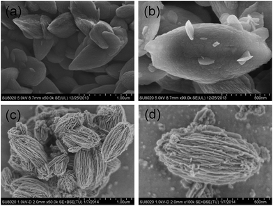
The structure of the samples was characterized by field emission scanning electron microscopy (FESEM), transmission electron microscopy (TEM) and high resolution transmission electron microscopy (HRTEM). Fig. 2a displays an FESEM image of the LFP particles synthesized by a solvothermal method at 160 °C for 8 hours. These petal shaped LFPs show quite a uniform distribution of particle size with an average diameter of ∼500 nm and length of ∼1 μm. From the higher magnified SEM images (Fig. 2b), it can be clearly observed that these similar-sized LFP petals are stacked together without rules. Fig. 2c shows the typical sample synthesized by mixing LC with a very uniform, carambola-like architecture ∼400 nm in diameter and ∼700 nm in length. The detailed morphology of the carambola-like nanostructure is shown in Fig. 2d, which reveals the entire lamellar surface. Interestingly, each nanopetal is connected to each other through the center to form hierarchically carambola structures, which can be vividly demonstrated by the SEM images of a sphere fringe (Fig. 2d).
X-ray diffraction (XRD) patterns of the as-synthesized LFP and carbon coated LFP materials are shown in Fig. S1 (see experimental details in the ESI†). All diffraction peaks agree well with those of phospho-olivine LFP indexed to the orthorhombic Pnma space group. The diffraction peaks of the n-LFP@C and c-LFP@C become much sharper, suggesting the improved crystallinity of LFP. According to the nitrogen adsorption/desorption isotherms (Fig. S2†), the Brunauer–Emmett–Teller surface areas of the n-LFP@C and c-LFP@C are 10.7 and 38.0 m2 g−1 (Table S1†), respectively. The X-ray photoelectron spectroscopy (XPS) spectra (Fig. S3a and b†) further demonstrate that the Fe 2p spectra of the LFP@C composite are split into two parts as a result of spin–orbit coupling and each part consists of a main peak and its satellite or a shoulder peak, which is characteristic for Fe2+.25
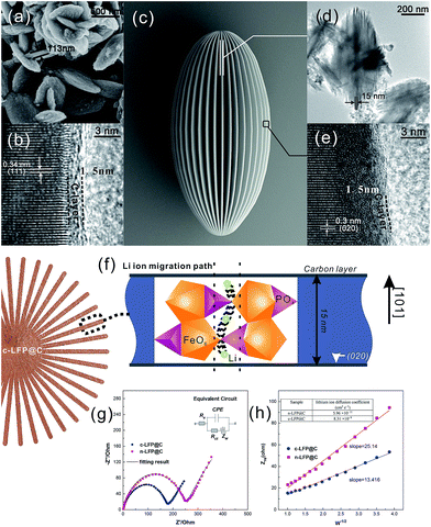
Fig. 3 shows the HRTEM images of carbon-coated LFP particles (sample n-LFP@C and c-LFP@C). The slices with a thickness of 15 nm of the c-LFP@C are shown in Fig. 3d and the n-LFP@C particles with a thickness of 113 nm in are shown in Fig. 3a. These results show that the liquid crystal directing method can reduce the slice thickness observably. The lattice interplanar spacing of 0.34 nm corresponds to the (111) plane and the thickness of the carbon layer is about 1.5 nm of n-LFP@C (Fig. 3b), respectively. However, Fig. 3e shows that the carbon layer coated on the c-LFP@C is about 1.5 nm thick. As we know, the role of carbon is to improve the electric conductivity of LFP and this electron transform process takes place on the interface between LFP and carbon. Therefore, the synthesized LFP/C with the same thickness of the carbon layer is the key we had focused. As Fig. 3b and e show, the thicknesses of the carbon layer on the c-LFP@C and n-LFP@C are almost the same.
Fig. 3e also shows clear crystal lattices, in which the lattice interplanar spacing of 0.3 nm corresponds to the (020) plane. This result demonstrates that the Li+ migration path in olivine LiFePO4 is along the [010]Pnma direction. And the thickness of the LFP layer determined the length of the Li+ migration channel. Therefore, the reduced slice thickness (15 nm shown in Fig. 3d) can decline the overpotential and capacity fading resulting from volume changes and allow better reaction kinetics at the electrode surface, reflecting in improved rate performances. Fig. 3c shows the schematic illustration of c-LFP@C.
It is often assumed that the migrating ion takes the shortest path between adjacent sites, that is, a direct linear jump. However, the favored migration mechanism (migration between adjacent Li ion sites along the [010] direction) along the [010] channel reveals a small deviation from the linear (straight) route involving a curved path between adjacent Li sites. This produces a “wavelike” trajectory for long-range migration as illustrated in Fig. 3f (ref. 22) and results in a lower migration energy than if the Li ion followed a direct, linear path. In addition, the carambola-like structure enhances the Li ion migration efficiency tremendously, resulting from the interface area of about 38.0 m2 g−1 (Table S1†).
Electrochemical impedance spectroscopy (EIS) examination was conducted to further clarify the difference in the electrochemical response of two carbon coated LFP cathode materials. As depicted in Fig. 3g, these impedance spectra consisted of a depressed semicircle in the high frequency region and a straight line in the low-frequency region, and a simple equivalent circuit was established to simulate the spectra (the inset in Fig. 3g). The semicircle is mainly associated with the charge-transfer resistance and the corresponding capacitance at the electrode–electrolyte interface, the straight line in the low frequency region is related to the diffusion behavior of lithium ions.26–28 The charge-transfer resistance (Rct) is calculated from the semicircle in the high–middle frequency range to be about 180 Ω and 255 Ω for the c-LFP@C and n-LFP@C (table inset in Fig. 3h), respectively; the c-LFP@C electrode exhibits lower charge-transfer resistance, suggesting that the electrolyte–electrode complex reactions can occur easily. The smaller slope of impedance of n-LFP@C samples indicates their higher electrochemical activity, which is ascribed to the fact that the hierarchical porous structure facilitates the diffusion path of lithium ions. The improved lithium-ion diffusion process within c-LFP@C particles estimated from the oblique line at low frequencies is greatly enhanced by uniform carbon coating and electrolyte penetration, improving the electronic conductivity and reducing the diffusion path of the lithium ions.
| ZRe = Re + Rct + σwω−1/2 | (1) |
 | (2) |
Fig. 3h shows the relationship between ZRe and square root of frequency (ω−1/2) in the low frequency region. From eqn (1), the Warburg impedance coefficients (σw) of the LFP samples were obtained, which are 13.416 and 25.14 cm2 s−1/2, respectively, for c-LFP@C and n-LFP@C. Based on the obtained Warburg impedance coefficients, the Li ion diffusion coefficients of samples can be calculated using eqn (2),29,30 the Li ion diffusion coefficients of the n-LFP@C and c-LFP@C are found to be 5.96 × 10⁻¹¹ and 8.31 × 10⁻⁹ cm2 s−1, respectively. The results clearly show that the Li ion diffusion coefficient of LFP nanocomposites could be increased with the decrease of the Li ion migration path which would improve the conductive interconnection among the adjacent LFP particles, and enhanced with further load of the carbon layer which forms more conductive paths for electrons improve the electron transfer efficiency and benefit the electrical conductivity of LFP. This clearly indicates that the liquid crystal directing method reduces the resistance, enhancing the charge transfer across the electrode–electrolyte interface.
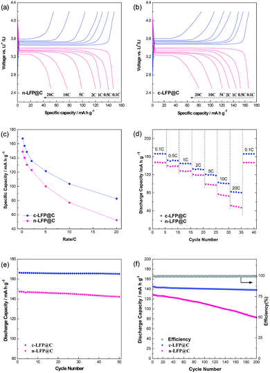
Fig. 4a and b display the galvanostatic charge and discharge voltage profiles of cells for LFP@C samples at progressively increasing C rates from 0.1 to 20 C between 2.5 and 4.2 V vs. Li+/Li. Fig. S4† compares the cyclic voltammetry (CV) curves of c-LFP@C and n-LFP@C samples at a scanning rate of 0.1 mV s−1 in the potential window of 2.5 to 4.2 V vs. Li+/Li. All the CV curves exhibit only one pair of well-defined anodic and cathodic peaks, which represent the Li+ deintercalation and reintercalation processes in the LiFePO4 crystal lattice, respectively. Accordingly, the dependence of specific capacity on the current density is shown in Fig. 4c. The c-LFP@C materials exhibit higher capacities than n-LFP@C at a low rate of 0.1 C, and a maximum capacity of 167.3 mA h g−1 (nearly to its theoretical capacity 170 mA h g−1), while that of the n-LFP@C reaches 148.8 mA h g−1. n-LFP@C displays lower capacity than c-LFP@C because of the lower lithium diffusion constant and electronic conductivity. Meanwhile, the result presents a serious polarization tendency at high C rates, while the c-LFP@C has a slight polarization tendency. It is noted that the voltage plateau is lengthened for the cholesteryl benzoate c-LFP@C materials, which should be attributed to the higher electrochemical reactivity of c-LFP@C and excellent kinetics. Fig. 4d shows the rate capabilities of LFP@C samples. When the C-rate increases from 0.1 to 20 C, c-LFP@C shows more satisfactory rate capability compared with n-LFP@C. It can be inferred that the structure with prior crystal growth on the (020) plane plays a significant role in improving the reaction kinetics of LFP, especially at high discharge rates (it could also remain 50% of theory capacity at 20 C), and this is also consistent with EIS measurements (Fig. 3g and h). We believe that the superior Li ion migration rate and electrical conductivity of c-LFP@C lead to the enhanced rate performance.
Fig. 4e and f show the cycling performance of sample n-LFP@C and c-LFP@C particles at 0.1 and 1 C. Fig. 4e shows the cyclability of c-LFP@C and n-LFP@C cathodes at a low current rate of 0.1 C. After 50 cycles, the cells still delivered a capacity of 165.7 (c-LFP@C, average 99.5% capacity retention) and 145.7 mA h g−1 (n-LFP@C, average 98.8% capacity retention), demonstrating ultra-high cyclability at low current rate for the c-LFP@C nanocomposites. Another excellent property of the c-LFP@C is the superior cycling performance. The discharge capacity of c-LFP@C corresponds to 138.1 mA h g−1 over 200 cycles at a rate of 1 C. And the Coulombic efficiency (calculated from the discharge capacity/charge capacity) always approaches 100%, as shown in the inset of Fig. 4f.
Conclusions
In summary, we have developed a new method using cholesteric benzoate as a structure-directing agent to synthesise LFP. A carambola-like LFP is prepared, which consists of LFP thin layers with a significantly shortened [010] channel of ∼15 nm with a selectively exposed (020) plane. The unique structure greatly promotes the Li+ diffusion along the preferential direction for Li storage, bringing an unprecedented Li+ diffusion coefficient of 8.31 × 10⁻⁹ cm2 s−1. On the other hand, we have successfully coated a highly conductive ultrathin carbon layer with controllable thickness (∼1.5 nm) onto the surface of LiFePO4 sheets, enabling fast electron transportation along the two-dimensional sheet. With the structural advantages of both components, a hierarchically mixed conducting network is formed, and the composite exhibits stable and extremely fast kinetics upon Li storage, which promises its use for high-power batteries with long lifespan. The composite exhibits stable and extremely fast electrochemistry upon Li storage by delivering almost a theoretical capacity (167 mA h g−1) at 0.1 C and ∼50% of the theoretical capacity (82 mA h g−1) at a high rate of 20 C, and exhibits stable cycling performances at different rates. In view of its favorable electrochemical performances, the composite material may find its use in LIBs with stable cyclability and high energy output for emerging EV applications. The strategy is simple, yet effective, and can bring inspiration to those working on high-energy batteries. All these will contribute to a better economic sustainability to benefit the whole industry.Acknowledgements
This work was supported by the Science and Technology Project of Anhui Province (1301022077) and the Science and Technology Project of Land and Resources of Anhui Province (2012-k-18).Notes and references
- B. Kang and G. Ceder, Nature, 2009, 458, 190–193 CrossRef CAS PubMed.
- M. Contestabile, G. Offer, R. Slade, F. Jaeger and M. Thoennes, Energy Environ. Sci., 2011, 4, 3754–3772 Search PubMed.
- O. K. Park, Y. Cho, S. Lee, H.-C. Yoo, H.-K. Song and J. Cho, Energy Environ. Sci., 2011, 4, 1621–1633 CAS.
- L. Ji, M. Rao, H. Zheng, L. Zhang, Y. Li, W. Duan, J. Guo, E. J. Cairns and Y. Zhang, J. Am. Chem. Soc., 2011, 133, 18522–18525 CrossRef CAS PubMed.
- A. K. Padhi, K. Nanjundaswamy and J. B. d. Goodenough, J. Electrochem. Soc., 1997, 144, 1188–1194 CrossRef CAS PubMed.
- A. Padhi, K. Nanjundaswamy, C. Masquelier, S. Okada and J. Goodenough, J. Electrochem. Soc., 1997, 144, 1609–1613 CrossRef CAS PubMed.
- L.-X. Yuan, Z.-H. Wang, W.-X. Zhang, X.-L. Hu, J.-T. Chen, Y.-H. Huang and J. B. Goodenough, Energy Environ. Sci., 2011, 4, 269–284 CAS.
- L. Wang, X. He, W. Sun, J. Wang, Y. Li and S. Fan, Nano Lett., 2012, 12, 5632–5636 CrossRef CAS PubMed.
- Y. Wu, Z. Wen and J. Li, Adv. Mater., 2011, 23, 1126–1129 CrossRef CAS PubMed.
- C. Zhang, X. He, Q. Kong, H. Li, H. Hu, H. Wang, L. Gu, L. Wang, G. Cui and L. Chen, CrystEngComm, 2012, 14, 4344–4349 RSC.
- X. Lou and Y. Zhang, J. Mater. Chem., 2011, 21, 4156–4160 RSC.
- L. Shen, C. Yuan, H. Luo, X. Zhang, K. Xu and Y. Xia, J. Mater. Chem., 2010, 20, 6998–7004 RSC.
- L. Gu, C. Zhu, H. Li, Y. Yu, C. Li, S. Tsukimoto, J. Maier and Y. Ikuhara, J. Am. Chem. Soc., 2011, 133, 4661–4663 CrossRef CAS PubMed.
- K. Weichert, W. Sigle, P. A. van Aken, J. Jamnik, C. Zhu, R. Amin, T. Acartuerk, U. Starke and J. Maier, J. Am. Chem. Soc., 2012, 134, 2988–2992 CrossRef CAS PubMed.
- X. L. Wu, Y. G. Guo, J. Su, J. W. Xiong, Y. L. Zhang and L. J. Wan, Adv. Energy Mater., 2013, 3, 1155–1160 CrossRef CAS.
- Y. Wang, Y. Wang, E. Hosono, K. Wang and H. Zhou, Angew. Chem., Int. Ed., 2008, 47, 7461–7465 CrossRef CAS PubMed.
- S. W. Oh, S. T. Myung, S. M. Oh, K. H. Oh, K. Amine, B. Scrosati and Y. K. Sun, Adv. Mater., 2010, 22, 4842–4845 CrossRef CAS PubMed.
- C. Sun, S. Rajasekhara, J. B. Goodenough and F. Zhou, J. Am. Chem. Soc., 2011, 133, 2132–2135 CrossRef CAS PubMed.
- H. L. Fei, Z. W. Peng, Y. Yang, L. Li, A. R. O. Raji, E. L. G. Samuel and J. M. Tour, Chem. Commun., 2014, 50, 7117–7119 RSC.
- J. Yang, J. Wang, X. Li, D. Wang, J. Liu, G. Liang, M. Gauthier, Y. Li, D. Geng, R. Li and X. Sun, J. Mater. Chem., 2012, 22, 7537–7543 RSC.
- A. Vu and A. Stein, Chem. Mater., 2011, 23, 3237–3245 CrossRef CAS.
- M. S. Islam, D. J. Driscoll, C. A. Fisher and P. R. Slater, Chem. Mater., 2005, 17, 5085–5092 CrossRef CAS.
- H. Takezoe and Y. Takanishi, Jpn. J. Appl. Phys., 2006, 45, 597–625 CrossRef CAS.
- (a) P. G. De Gennes and J. Prost, The physics of liquid crystals, Oxford University Press, New York, 1993 Search PubMed; (b) E. Olbrich, O. Marinov and D. Davidov, Phys. Rev. E: Stat. Phys., Plasmas, Fluids, Relat. Interdiscip. Top., 1993, 48, 2713 CrossRef CAS.
- M. Bhuvaneswari, N. N. Bramnik, D. Ensling, H. Ehrenberg and W. Jaegermann, J. Power Sources, 2008, 180, 553–560 CrossRef CAS PubMed.
- T. Muraliganth, A. V. Murugan and A. Manthiram, J. Mater. Chem., 2008, 18, 5661–5668 RSC.
- J. Xiang, J. Tu, L. Zhang, X. Wang, Y. Zhou, Y. Qiao and Y. Lu, J. Power Sources, 2010, 195, 8331–8335 CrossRef CAS PubMed.
- X. L. Li, W. Guo, Y. F. Liu, W. X. He and Z. H. Xiao, Electrochim. Acta, 2014, 116, 278–283 CrossRef CAS PubMed.
- J. Chlistunoff, D. Cliffel and A. J. Bard, Thin Solid Films, 1995, 257, 166–184 CrossRef CAS.
- A. Bard and L. Faulkner, Electrochemical Methods, Wiley, New York, 1980 Search PubMed.
Footnote |
| † Electronic supplementary information (ESI) available. See DOI: 10.1039/c4ta04358h |
| This journal is © The Royal Society of Chemistry 2015 |


