Microwave-assisted ionothermal synthesis of SnSex nanodots: a facile precursor approach towards SnSe2 nanodots/graphene nanocomposites†
Cheng-Feng Duab,
Jian-Rong Lia and
Xiao-Ying Huang*a
aState Key Laboratory of Structural Chemistry, Fujian Institute of Research on the Structure of Matter, Chinese Academy of Sciences, Fuzhou, Fujian 350002, People's Republic of China. E-mail: xyhuang@fjirsm.ac.cn
bUniversity of Chinese Academy of Sciences, Beijing, 100049, People's Republic of China
First published on 12th January 2016
Abstract
Presented here is a facile approach towards spherical SnSe2 nanodots/graphene nanocomposites via an ionic liquid media assembly process, which involved an easily scaled-up microwave-assisted ionothermal synthesis of SnSex nanodots (NDs) as precursors by the reaction of elementary tin and selenium in (Bmmim)Cl (Bmmim = 1-butyl-2,3-dimethyl imidazolium) followed by an assembly process under ambient conditions and subsequent thermal treatment. The regulation of the content of SnSe2 NDs could be conveniently achieved by varying the ratio of ND precursor to graphene oxide (GO). As evidenced by TG-MS and FTIR analysis, the assembly process could be attributed to the electrostatic interaction between the anionic GO and the positively charged SnSex NDs, which are fixed in the IL cation layer around the NDs as a medium. This conclusion was further confirmed by the TEM micrographs, which showed a constant particle size in the precursor and in the nanocomposites after thermal treatment. Lithium storage characterizations showed that the capacity of the as-prepared nanocomposite remained at 659 mA h g−1 after 30 cycles at a current density of 150 mA g−1, which is 1.5-times better than the theoretical capacity of SnSe2 (426 mA h g−1) and superior to the capacities of the previously reported SnSe2 nanoplate/graphene composite and many other tin selenide electrodes. Thus, the new approach represents a promising, simple, and scalable synthetic protocol for the fabrication of lamellar metal dichalcogenide (LMD) NDs/graphene nanocomposites.
Introduction
Due to the low cost, high surface area, high conductivity and high chemical inertness, graphene and its derivatives have attracted particular interest as functional materials.1–8 They can be compounded with various nanomaterials to form graphene-based nanocomposites, which have been widely used in energy conversion and storage, catalysis, environmental, medical and electronic applications.9–15The control of the size, morphology and dispersion of nanomaterials on graphene is crucial for developing high-performance graphene-based nanocomposite materials. For instance, the small particle size of electrode materials for Li-ion batteries can endow high surface area to buffer the volume change and shorten the diffusion length for Li ions, thus improving the cycle stability and rate capability.16,17 Therefore, nanomaterials with certain morphologies, e.g. nanodots (NDs), are highly desirable in graphene-based nanocomposites. To date, a number of metal oxide NDs/graphene nanocomposites have been obtained.17–19 In contrast, the lamellar metal dichalcogenides (LMDs), an important class of lithium storage materials, are strongly inclined to grow on graphene two-dimensionally (2D) as nanoplates or nanoshells due to the lamellar nature of LMDs and the graphene support.20–24 Thus far, the synthesis of LMDs NDs/graphene nanocomposites has proven challenging.25
Ionic liquids (ILs) have emerged as a type of functional material and green solvent.26–31 The unique physical properties of ILs, such as high thermal stability, high solubility, low vapour pressure, low toxicity and self-template effect, make them suitable for inorganic synthesis.30,32 It has been demonstrated that ILs can serve as alternative solvents in the synthesis of metal chalcogenides.33–37 On the other hand, due to the high microwave absorbing property of ILs, the microwave-assisted ionothermal process has become a promising route to acquiring various metal chalcogenide nanomaterials.33,38,39 In our previous work, we found that the ionothermal treatment of a mixture of Sn and Se powders in 1,2,3-trialkylimidazolium-based ILs could result in a homogeneous ionic gel, from which the nanoparticles of new selenidostannate phases could be obtained.34 In addition, the high affinity of ILs on nanocarbon and their mediator role in the assembly of nanocomposites has recently received considerable attention.40–42 Therefore, we hoped to develop an IL-media assembly approach towards LMD NDs/graphene nanocomposites utilizing the microwave-assisted ionothermal synthesized LMD NDs as precursors.
Herein, by choosing SnSe2, a typical LMD, as the model compound, a facile approach towards spherical SnSe2 NDs/reduced graphene oxide nanocomposites (denoted as SnSe2 NDs@rGO) was developed. The approach involved the microwave-assisted ionothermal synthesis of SnSex NDs@Bmmim precursors (Bmmim = 1-butyl-2,3-dimethyl imidazolium) in the first step followed by an IL-media assembly process and thermal treatment. The lithium storage characterizations showed that the as-prepared SnSe2 NDs@rGO nanocomposites had a good lithium ion storage performance; the optimal SnSe2 NDs@rGO nanocomposite exhibited a reversible capacity of 717 mA h g−1, and the capacity was retained at 659 mA h g−1 after 30 cycles at a current density of 150 mA g−1.
Experimental
Materials and physical measurements
Tin (99.5%) powder was purchased from Sinopharm Chemical Reagent, selenium (analytical grade) powder was purchased from Tianjin Yingda Rare Chemical Reagent, and (Bmmim)Cl (99%) was purchased from Lanzhou Greenchem ILS, LICP. CAS. China. GO powder that was synthesized by a common Hummers' method was provided by XFNANO Materials Tech Co., Ltd. All of the chemicals were used without further purification. Field-emission scanning electron microscopy (FESEM) images were acquired on a JSM-6700F field-emission scanning electron microscope. Transmission electron microscopy (TEM) images were acquired on a JEM-2010 transmission electron microscope. Powder X-ray diffraction (PXRD) patterns were recorded on a Rigaku Mini Flex II diffractometer using CuKα radiation. Elemental analysis was performed on a German Elementary Vario EL III instrument. Fourier-transform infrared (FTIR) spectroscopy was carried out on a Vertex 70 FTIR spectrophotometer using KBr pellets within the range of 4000–400 cm−1. X-ray photoelectron spectroscopy (XPS) was conducted on an ESCALAB 250Xi XPS spectrometer. Thermogravimetric analysis (TGA) was carried out at a heating rate of 5 °C min−1 in a N2 atmosphere from 30 °C to 800 °C on a NETZSCH STA 449F3 unit under N2 atmosphere. Thermal analysis-mass spectroscopy (TG-MS) was carried out at a heating rate of 5 °C min−1 in N2 atmosphere from 30 °C to 800 °C on a STA449C-QMS403C thermal analysis-quadrupole mass spectrometer.Preparation of SnSex NDs precursor
The precursor SnSex NDs with diameters of 5 nm were prepared through a microwave-assisted ionothermal process. The microwave experiments were carried out on a microwave reactor with a maximum power of 300 W (Biotage Initiator™ EXP). Typically, 0.238 g of tin powder (2 mmol) and 0.348 g selenium powder (4.4 mmol) were mixed with 2 g of (Bmmim)Cl (10.4 mmol, Bmmim = 1-butyl-2,3-dimethylimidazolium) in a 10 mL Biotage microwave vial. The vial was sealed and heated (100 °C) in a water bath to form a mash-like mixture. The mixture was then heated under microwave using a controlled program (typically, the mixture was heated at 120 °C for 5 minutes followed by 180 °C for 55 minutes and then cooled to room temperature) with magnetic stirring, which resulted in a transparent dark-red solution. The maximum heating power was set to 100 W. During the cooling process, the viscosity of the product increased significantly. Finally, a dark-red gel containing crystalline spherical SnSex NDs was formed.Assembly of SnSex NDs with GO
The above SnSex NDs precursor was dissolved in 15 mL 1-N-methyl-2-pyrrolidinone (NMP) under stirring for 5 minutes, and the resultant solution was kept at 4 °C for 5 hours to allow the precipitation of the excess (Bmmim)Cl. After centrifugation, a clear orange solution was obtained for further characterization.For the assembly of NDs with GO, 200 mg GO was dispersed in 5 mL deionized water (DI water) and sonicated for 30 minutes. Then, 10 mL of absolute ethanol and 10 mL NMP were added, and the mixture was sonicated for another 30 minutes. The clear NDs precursor/NMP solution was added dropwise into the GO solution under vigorous stirring and kept stirring for 30 minutes under ambient conditions. Then, 50 mL of absolute ethanol was added followed by the dropwise addition of 20 mL DI water. The solution was stirred for 30 minutes, and the nanocomposites of [Bmmim]+ cation-wrapped NDs encapsulated in GO (denoted as SnSex NDs@Bmmim@GO) were harvested by suction filtration and washed with water and ethanol several times. The products were then dried at 60 °C under vacuum for 5 hours. In order to obtain well-crystalline SnSe2 NDs@rGO nanocomposites, the as-synthesized products were annealed under N2 at 300 °C for 2 hours at a heating rate of 2 °C min−1.
Three composites denoted as NG-1, NG-2 and NG-3 were synthesized by 200 mg GO composited with different amounts of NDs precursor/NMP solutions (3, 7, and 14 mL, respectively). For the control experiments, the annealed GO (in absence of NDs precursor) and annealed NDs precursors were also prepared using similar routes.
Electrochemical measurements
The electrochemical tests were performed using CR2025 coin-type test cells. To fabricate the working electrodes, 80 wt% active material, 10 wt% conductivity agent (TIMCAL SUPER C45 Carbon Black), and 10 wt% polyvinylidene fluoride binder (PVDF) were mixed with NMP and then pasted on Cu foil. The electrodes were dried at 60 °C for 3 hours followed by 120 °C for 15 hours in a vacuum oven. Cells were assembled in an Ar-filled glove box in which the concentrations of moisture and oxygen were below 1 ppm. Pure lithium foil was used as both the counter and reference electrodes. The electrolyte was 1 M LiPF6 in ethylene carbonate/diethyl carbonate (EC/DEC, 1![[thin space (1/6-em)]](https://www.rsc.org/images/entities/char_2009.gif) :
:![[thin space (1/6-em)]](https://www.rsc.org/images/entities/char_2009.gif) 1 by volume). A Celgard 2325 membrane was used as the separator. The galvanostatic discharge/charge cycles were carried out on a LAND 2001A system over a voltage range of 0.05 to 3.00 V at 30 °C. Cyclic voltammetry (CV) and electrochemical impedance spectroscopy (EIS) were performed on a CHI660E Electrochemical Workstation. The specific capacities in this article were calculated based on the overall masses of the nanocomposites.
1 by volume). A Celgard 2325 membrane was used as the separator. The galvanostatic discharge/charge cycles were carried out on a LAND 2001A system over a voltage range of 0.05 to 3.00 V at 30 °C. Cyclic voltammetry (CV) and electrochemical impedance spectroscopy (EIS) were performed on a CHI660E Electrochemical Workstation. The specific capacities in this article were calculated based on the overall masses of the nanocomposites.
Results and discussion
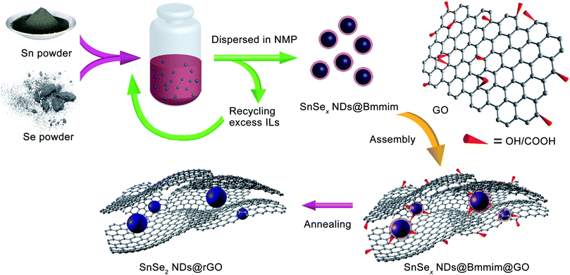
As shown in Scheme 1 and the ESI,† the overall synthetic procedure and assembly of SnSe2 NDs@rGO nanocomposite involves three steps: (1) the preparation of SnSex NDs@Bmmim precursor under microwave-assisted ionothermal conditions; (2) the subsequent assembly process; and (3) post thermal treatment by annealing at 300 °C for 2 h. As confirmed by TGA-MS, FTIR and XPS analyses, the assembly of SnSex NDs with GO can be attributed to the electrostatic interactions between the anionic GO and the positively charged SnSex NDs, which are fixed in the IL cation layer around the NDs as a medium.18,40,43,44 Three nanocomposites, denoted NG-1, NG-2 and NG-3, were synthesized with different ratios of SnSex NDs precursor to GO, as summarized in Table 1.Fig. 1a and b show the typical heating profiles of the program-controlled microwave-assisted ionothermal reaction and the photograph of an as-prepared precursor, respectively. After a very fast microwave-assisted ionothermal reaction, the homogeneous gel-like NDs precursor was obtained. Notably, the pressure of the microwave reactor was constantly 0 bar over the reaction process, implying that the reaction will remain safe when scaled up (Fig. S1, ESI†). The NDs precursor was then dispersed into 1-N-methyl-2-pyrrolidinone (NMP) to remove the precipitation of the excess ILs for further assembly (Fig. S2, ESI†).
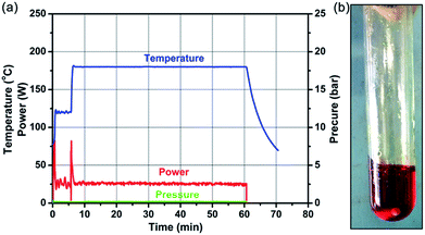 | ||
| Fig. 1 (a) Microwave heating profiles (temperature, power, and pressure) for a typical synthesis of NDs precursor in [Bmmim]Cl. (b) The as-prepared NDs precursor. | ||
The as-prepared SnSex NDs@Bmmim@GO composites were characterized by TG-MS analysis, PXRD and FTIR. As shown in Fig. S3,† the TG-MS profiles contained three weight-loss steps, clearly indicating the evaporation of adsorbed solvent, thermal decomposition of [Bmmim]+ and the phase transformation from SnSe2 to SnSe during the heating process. The PXRD pattern plotted in Fig. S4† showed no characteristic peaks of SnSe2, probably due to the formation of new selenidostannate phases.34 As shown in Fig. 2 (middle), the FTIR spectrum of the pristine nanocomposite exhibited a broad peak at 1647 cm−1, which could be assigned to the mixed peak of the C![[double bond, length as m-dash]](https://www.rsc.org/images/entities/char_e001.gif) O stretching band as the typical amide I band in case of cyclic tertiary amides in NMP and the C–C stretching vibration band of [Bmmim]+.45,46 Several other characteristic peaks at 1734, 1402 and 1059 cm−1 were assigned to the C
O stretching band as the typical amide I band in case of cyclic tertiary amides in NMP and the C–C stretching vibration band of [Bmmim]+.45,46 Several other characteristic peaks at 1734, 1402 and 1059 cm−1 were assigned to the C![[double bond, length as m-dash]](https://www.rsc.org/images/entities/char_e001.gif) O and single bound carboxyl (C–O) vibrations in the carboxylic acid or carbonyl moieties and C–O vibrations in the alkoxy groups of GO.43,47,48 Compared to the FTIR spectrum of (Bmmim)Cl (Fig. 2, top), the peaks at around 2925 and 2868 cm−1 were attributed to the two C–H vibrations of the –CH3 and –CH2 bands in [Bmmim]+. The C
O and single bound carboxyl (C–O) vibrations in the carboxylic acid or carbonyl moieties and C–O vibrations in the alkoxy groups of GO.43,47,48 Compared to the FTIR spectrum of (Bmmim)Cl (Fig. 2, top), the peaks at around 2925 and 2868 cm−1 were attributed to the two C–H vibrations of the –CH3 and –CH2 bands in [Bmmim]+. The C![[double bond, length as m-dash]](https://www.rsc.org/images/entities/char_e001.gif) C and C
C and C![[double bond, length as m-dash]](https://www.rsc.org/images/entities/char_e001.gif) N stretching, C–N stretching and in-plane C–H bending vibration of [Bmmim]+ could be found at 1498, 1300 and 1248 cm−1.49 The peaks at 829, 734 and 658 cm−1 were attributed to the C–H and C–N out-of-plane bending vibrations of [Bmmim]+.49,50 The broad peak at 3427 cm−1 could be assigned to the stretching vibrations of hydroxyl groups.
N stretching, C–N stretching and in-plane C–H bending vibration of [Bmmim]+ could be found at 1498, 1300 and 1248 cm−1.49 The peaks at 829, 734 and 658 cm−1 were attributed to the C–H and C–N out-of-plane bending vibrations of [Bmmim]+.49,50 The broad peak at 3427 cm−1 could be assigned to the stretching vibrations of hydroxyl groups.
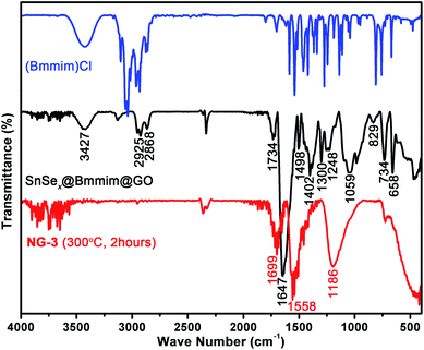 | ||
| Fig. 2 FTIR spectra of (Bmmim)Cl (top), the pristine SnSex NDs@Bmmim@GO nanocomposite (middle) and the annealed product (NG-3, bottom). | ||
The annealed samples (e.g., NG-3) were also characterized by PXRD and FTIR. As illustrated in Fig. S4a,† all the peaks can be readily indexed to the hexagonal SnSe2 phase (JCPDS card no. 89-3197), indicating high phase purity. As for the FTIR spectra of NG-3 (Fig. 2, bottom), the characteristic peaks of [Bmmim]+ disappeared, indicating the thermal decomposition and departure of [Bmmim]+ during the annealing process. Instead, three new peaks at 1699, 1558 and 1186 cm−1 appeared. The peaks at 1186 cm−1 and 1699 cm−1 can be ascribed to the vibrational modes of basal plane epoxides (C–O–C) and the C![[double bond, length as m-dash]](https://www.rsc.org/images/entities/char_e001.gif) O of the stable acid moieties.48,51 The peak at 1558 cm−1 may be from the skeletal vibrations of unoxidized graphitic domains, indicating the reduction of GO.43,51,52
O of the stable acid moieties.48,51 The peak at 1558 cm−1 may be from the skeletal vibrations of unoxidized graphitic domains, indicating the reduction of GO.43,51,52
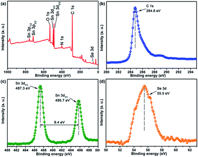
The FTIR spectra clearly indicated the existence and thermolysis of [Bmmim]+ cations, implying that the NDs were uniformly encapsulated in an IL cation matrix in the pristine nanocomposites. Thus, the assembly of SnSex NDs with GO could be attributed to the electrostatic interaction between the anionic GO and the positively charged SnSex NDs, which are fixed in the IL cation layer around the NDs as a medium.40,43,44,51,52 Consequently, the SnSe2 NDs could be assembled on the surface of rGO after annealing. To further confirm the composition of the as-obtained products and study the annealing process, XPS analysis was conducted on the annealed products. Fig. 3 shows the XPS spectra of NG-3. As shown in Fig. 3, the C1s peak in XPS spectra appeared at 284.8 eV, which was in accordance with both chemically converted and thermally converted graphene,53 indicating the reduction of GO. The small peak centred at 288.5 eV was attributed to the residual C![[double bond, length as m-dash]](https://www.rsc.org/images/entities/char_e001.gif) O group.54,55 The 3d peaks of Sn and Se appeared at 495.7, 487.3 eV and 55.5 eV, which matched well with those of tin and selenium in the stoichiometric SnSe2 phase in the material.21,56
O group.54,55 The 3d peaks of Sn and Se appeared at 495.7, 487.3 eV and 55.5 eV, which matched well with those of tin and selenium in the stoichiometric SnSe2 phase in the material.21,56
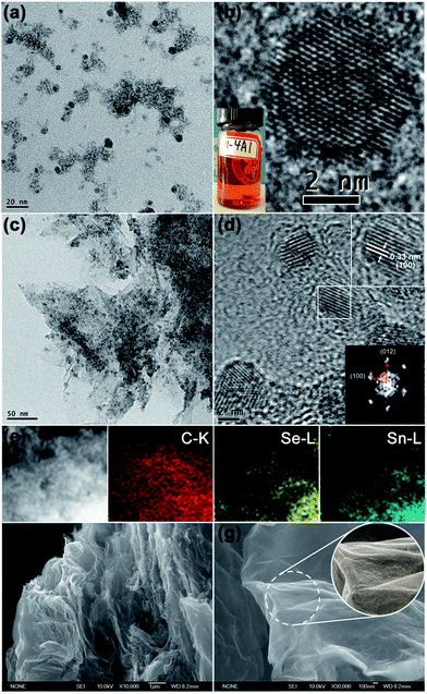
The NDs precursor was investigated by TEM and high-resolution (HR) TEM. As shown in Fig. 4a and b, the SnSex NDs in the precursor have regular spherical shapes with an average diameter of about 5 nm. The TEM and HRTEM images of annealed products (for example, NG-3) are shown in Fig. 4c and d, indicating that the NDs were uniformly distributed on the rGO substrate. The parallel lattice fringes of the NDs with interplanar distances of 0.33 nm (Fig. 4d, upper inset) were consistent with the (100) plane of hexagonal SnSe2, indicating the formation of SnSe2 NDs after annealing, which was also confirmed by the FFT analysis (Fig. 4d, lower inset). Importantly, the sizes of SnSe2 NDs remained around 5 nm without growth after annealing. The elemental mapping of SnSe2 NDs@rGO nanocomposites on carbon, selenium and tin further demonstrates the homogeneous and highly efficient combination of SnSe2 NDs and rGO (Fig. 4e). The morphology and microstructure of the as-prepared SnSe2 NDs@rGO nanocomposites were also investigated using FESEM. As seen in Fig. 4f and g, the as-prepared SnSe2 NDs@rGO nanocomposite (NG-3) possesses a rough surface and a disordered three-dimensional (3D) network structure composed of flexible rGO lamellae and SnSe2 NDs with interconnected pores ranging from several hundreds of nanometres to several micrometres in size. All the above-mentioned characterizations indicated the successful preparation of SnSe2 NDs@rGO nanocomposites in which the GO lamellae served as the ESI,† and the SnSe2 NDs were distributed uniformly on the surfaces of the rGO lamellae and homogeneously in the entire network.
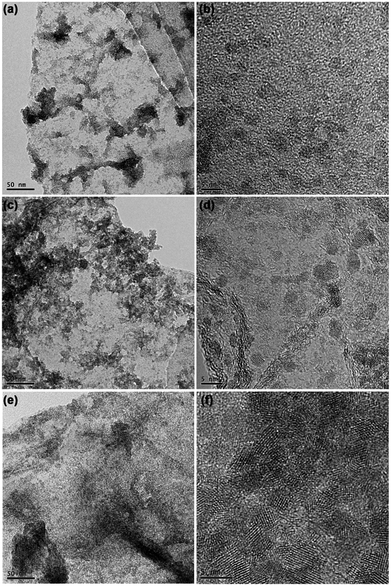
In addition, by modifying the ratios of SnSex ND precursor to GO, the loading contents of SnSe2 NDs on the rGO substrate could be adjusted. Fig. 5 shows the representative TEM and HRTEM micrographs of the three nanocomposites. On the basis of the micrographs shown in Fig. 5, the loading of SnSe2 NDs on the rGO substrate increased as the ratio of SnSex ND precursor to GO increased. Consistent with this qualitative observation, the elemental analysis of the carbon content in the three composites quantitatively confirmed the results (see Table 1). Obviously, the assembly process we developed here was convenient for the regulation of ND content. Notably, although the loading of SnSe2 NDs on the rGO substrate increased, the diameters of the NDs in the three nanocomposites were nearly the same, further verifying that the SnSex NDs were uniformly encapsulated in a matrix of [Bmmim]+ cations that separated the NDs during the annealing process.
The preparative methods of metal chalcogenide nanomaterial/graphene nanocomposites include both one-pot and step-by-step strategies. In the one-pot synthesis, the typical hydro/solvothermal procedures often suffer from the high solvent pressure and expensive or highly toxic reagents like alkyl phosphine, CS2 and H2S, seriously limiting their practical applications.24 The method we developed here is a step-by-step approach. Through a one-pot program-controlled microwave-assisted ionothermal process, crystalline spherical SnSex NDs with diameters of approximately 5 nm were easily obtained using low-cost elementary substances as reactants and could be separated and used as precursors for further assembly. In the subsequent assembly process, the ILs not only stabilized the spherical SnSex NDs, but also induced the SnSex NDs to preferentially form composites with rGO. Also worth mentioning is that the microwave-assisted ionothermal reaction was carried out under negligible vapour pressure within an hour, and the assembly process proceeded under ambient conditions, which saves time, and could easily be scaled up. The excess ILs dissolved from the NMP solution in step (1) could also be recycled for further use. To the best of our knowledge, this is the first report of the preparation of LMDs NDs/graphene nanocomposites.
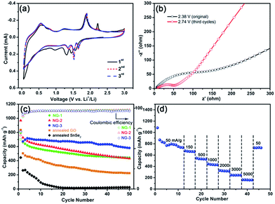
Although SnSe2 is a congener of SnS2, which has been widely investigated as a lithium storage material, similar studies on SnSe2 are still quite limited.21 Herein, the electrochemical performances of the SnSe2 NDs@rGO nanocomposites were evaluated by CV and galvanostatic charge–discharge cycling. The CV curves for the first three cycles of NG-3 at a scanning rate of 0.1 mV s−1 are shown in Fig. 6a. In the CV curves, the peak at 0.97 V in the first cathodic sweep disappeared in the following cycles, which can be attributed to solvent decomposition and the formation of a solid electrolyte interface (SEI) layer on the electrode surface.57 After the first cycle, the four cathodic peaks at 0.25, 1.37, 1.52 and 1.65 V in the cathodic scan and three anodic peaks at 0.54, 1.25, and 1.89 V in the anodic scan for the electrode should mainly result from the Li alloying/dealloying reactions with SnSe2.58,59 According to the literature, the lithiation processes of tin dichalcogenides (Q = S or Se) could be elucidated as follows:
| SnQ2 + xLi+ + xe− ↔ LixSnQ2 | (1) |
| LixSnQ2 + (y − x)Li+ + (y − x)e− ↔ LiySnQ2 | (2) |
| LiySnQ2 + (4 − y)Li+ + (4 − y)e− ↔ Sn + 2Li2Q (1 ≤ x ≤ y ≤ 2) | (3) |
| SnQ2 + 4Li+ + 4e− ↔ Sn + 2Li2Q | (4) |
| Sn + 4.4Li+ + 4e− ↔ Li4.4Sn | (5) |
Reactions (1)–(3) represent the lithium intercalation into the chalcogenide layers and the conversion reactions above 1.3 V, which could be summarized by reaction (4). Reaction (5) represents the alloying reaction of lithium below 0.5 V.59,60 During the subsequent cycles, the CV curves of the SnSe2 NDs@rGO composites displayed a constant integral area, indicating that the nanocomposite was capable of electrochemical lithium storage. The electrochemical impedance spectra of the NG-3 electrode recorded before and after the CV characterization are shown in Fig. 6b. The semicircle diameters of the NG-3 electrodes decrease after the CV characterization, suggesting that after full charging/discharging cycles, the NG-3 possessed a higher electrical conductivity and a faster charge–transfer reaction for Li-ion insertion and extraction.61 Similar phenomena were also found in metal oxide and silicon anodes,62,63 which might originate from the physical restructuring of the SEI film.64
The cycling performances and rate capabilities of the nanocomposites are shown in Fig. 6c and d, respectively. As shown in Fig. 6c, the first discharge capacity of the as-prepared SnSe2 NDs@rGO nanocomposites at a current density of 150 mA g−1 could surpass 800 mA h g−1, and the discharge capacity could be retained at 659 mA h g−1 after 30 cycles, which is much higher than its theoretical value of 426 mA h g−1. The capacity of the SnSe2 NDs@rGO nanocomposites increased with increasing ND content; however, the cycling performance first decreased and then increased with increasing ND content. The differences among these three samples implied that the cycling stability of graphene-based nanocomposites is related to the dispersity of nanoparticles and graphene.65 For comparison, the annealed NDs precursor and annealed GO cycled at a current density of 150 mA g−1 are also shown in Fig. 6c. The cycling capacity of the annealed NDs precursor decayed rapidly to about 50 mA h g−1 over several cycles. The same phenomenon occurred in simplex-annealed GO (about 200 mA h g−1), which further confirms that the simplex SnSe2 is unstable during the lithiation/delithiation process, and GO does not contribute considerably to the capacity of the integrated electrode. This illustrates that the nanocomposites of SnSe2 NDs and rGO provide the majority of the capacity and stability of the integrated anode.
Fig. 6d shows the rate performances of the NG-3 nanocomposite at various current densities ranging from 50 to 5000 mA g−1. These curves exhibited similar shapes with only a small over potential and high capacities even at large current densities. As shown in Fig. 6b, the specific capacities of NG-3 were 796, 668, 534, 435, 323, 244 and 162 mA h g−1 when cycled at 50, 150, 500, 1000, 2000, 3000 and 5000 mA g−1, respectively. Even at a current density of 1000 mA g−1, NG-3 still delivered a capacity of 435 mA h g−1, which was higher than the theoretical capacity (426.3 mA h g−1) of the SnSe2 anode. When cycled back to 50 mA g−1, a capacity of 729 mA h g−1 could be restored and kept stable, indicating the good stability of the NG-3 nanocomposite. To our knowledge, the only example of a SnSe2/graphene composite for application in lithium-ion batteries is an SnSe2 nanoplate/graphene composite,21 which could only retain a reversible discharge capacity of 470–640 mA h g−1 at a current density of 40 mA g−1 after 30 cycles (summarized in Table 2). Compared to the low current density and cycling capacity of the SnSe2 nanoplate/graphene composite, the SnSe2 NDs@rGO nanocomposites in this work exhibit an improved performance due to the good dispersion and high surface area.
| Composition | Id (mA g−1) | Num | Ctheo (mA h g−1) | Cexp (mA h g−1) | Improvement (times) | Ref. |
|---|---|---|---|---|---|---|
| a Id = current density. Num = cycle number. Ctheo = theoretical capacity. Cexp = experimental capacity.b Reported in this work. | ||||||
| SnSe2 nanoplate/rGO | 40 | 30 | 426 | 470–640 | 1.10–1.50 | 21 |
| NG-3 | 150 | 30 | 426 | 659 | 1.55 | b |
| SnSe film | 130 | 40 | 596 | 400 | 1.06 | 58 |
| SnSe/carbon fibre | 200 | 80 | 596 | 676 | 1.13 | 66 |
| SnSe nanocrystals | 60 | 30 | 596 | <200 | <0.34 | 67 |
Conclusions
In summary, we demonstrated a novel step-by-step method for acquiring SnSe2 NDs@rGO nanocomposites under ambient conditions. When evaluated as an anode material for lithium-ion batteries, these SnSe2 NDs@rGO nanocomposites show significantly enhanced electrochemical performance with high capacity, excellent cycling stability and good rate capability. This method provides a simple and scalable synthetic approach for the fabrication of LMDs NDs/graphene nanocomposites.Acknowledgements
This work was financially supported by the 973 program (no. 2014CB845603) and the NNSF of China (no. 21521061 and 21371001).Notes and references
- D. R. Dreyer, S. Park, C. W. Bielawski and R. S. Ruoff, Chem. Soc. Rev., 2010, 39, 228–240 RSC.
- M. J. Allen, V. C. Tung and R. B. Kaner, Chem. Rev., 2010, 110, 132–145 CrossRef CAS PubMed.
- J. X. Zhu, D. Yang, Z. Y. Yin, Q. Y. Yan and H. Zhang, Small, 2014, 10, 3480–3498 CrossRef CAS PubMed.
- Z. Sun and H. Chang, ACS Nano, 2014, 8, 4133–4156 CrossRef CAS PubMed.
- S. Stankovich, D. A. Dikin, R. D. Piner, K. A. Kohlhaas, A. Kleinhammes, Y. Jia, Y. Wu, S. T. Nguyen and R. S. Ruoff, Carbon, 2007, 45, 1558–1565 CrossRef CAS.
- D. Li, M. B. Muller, S. Gilje, R. B. Kaner and G. G. Wallace, Nat. Nanotechnol., 2008, 3, 101–105 CrossRef CAS PubMed.
- F. Bonaccorso, Z. Sun, T. Hasan and A. C. Ferrari, Nat. Photonics, 2010, 4, 611–622 CrossRef CAS.
- Y. W. Zhu, S. Murali, W. W. Cai, X. S. Li, J. W. Suk, J. R. Potts and R. S. Ruoff, Adv. Mater., 2010, 22, 3906–3924 CrossRef CAS PubMed.
- Y. Sun, X. Hu, W. Luo, J. Shu and Y. Huang, J. Mater. Chem. A, 2013, 1, 4468 CAS.
- C. C. Huang, C. Li and G. Q. Shi, Energy Environ. Sci., 2012, 5, 8848–8868 CAS.
- X. Huang, Z. Y. Zeng, Z. X. Fan, J. Q. Liu and H. Zhang, Adv. Mater., 2012, 24, 5979–6004 CrossRef CAS PubMed.
- Y. X. Liu, X. C. Dong and P. Chen, Chem. Soc. Rev., 2012, 41, 2283–2307 RSC.
- Q. J. Xiang, J. G. Yu and M. Jaroniec, Chem. Soc. Rev., 2012, 41, 782–796 RSC.
- N. Zhang, Y. H. Zhang and Y. J. Xu, Nanoscale, 2012, 4, 5792–5813 RSC.
- D. Jariwala, V. K. Sangwan, L. J. Lauhon, T. J. Marks and M. C. Hersam, Chem. Soc. Rev., 2013, 42, 2824–2860 RSC.
- C. Peng, B. Chen, Y. Qin, S. Yang, C. Li, Y. Zuo, S. Liu and J. Yang, ACS Nano, 2012, 6, 1074–1081 CrossRef CAS PubMed.
- R. W. Mo, Z. Y. Lei, K. N. Sun and D. Rooney, Adv. Mater., 2014, 26, 2084–2088 CrossRef CAS PubMed.
- Y. Q. Luo, S. S. Fan, Y. M. Luo, N. Y. Hao, S. L. Zhong and W. C. Liu, CrystEngComm, 2015, 17, 1741–1744 RSC.
- H. Wang, L. F. Cui, Y. Yang, H. Sanchez Casalongue, J. T. Robinson, Y. Liang, Y. Cui and H. Dai, J. Am. Chem. Soc., 2010, 132, 13978–13980 CrossRef CAS PubMed.
- Y. Li, H. Wang, L. Xie, Y. Liang, G. Hong and H. Dai, J. Am. Chem. Soc., 2011, 133, 7296–7299 CrossRef CAS PubMed.
- J. Choi, J. Jin, I. G. Jung, J. M. Kim, H. J. Kim and S. U. Son, Chem. Commun., 2011, 47, 5241–5243 RSC.
- K. Chang and W. X. Chen, Chem. Commun., 2011, 47, 4252–4254 RSC.
- Y. P. Wang, B. B. Qian, H. H. Li, L. Liu, L. Chen and H. B. Jiang, Mater. Lett., 2015, 141, 35–38 CrossRef CAS.
- T. F. Zhou, W. K. Pang, C. F. Zhang, J. P. Yang, Z. X. Chen, H. K. Liu and Z. P. Guo, ACS Nano, 2014, 8, 8323–8333 CrossRef CAS PubMed.
- W. Gao, M. Wang, C. Ran and L. Li, Chem. Commun., 2015, 51, 1709–1712 RSC.
- T. Welton, Chem. Rev., 1999, 99, 2071–2083 CrossRef CAS PubMed.
- M. Armand, F. Endres, D. R. MacFarlane, H. Ohno and B. Scrosati, Nat. Mater., 2009, 8, 621–629 CrossRef CAS PubMed.
- J. Le Bideau, L. Viau and A. Vioux, Chem. Soc. Rev., 2011, 40, 907–925 RSC.
- E. Boros, M. J. Earle, M. A. Gilea, A. Metlen, A. V. Mudring, F. Rieger, A. J. Robertson, K. R. Seddon, A. A. Tomaszowska, L. Trusov and J. S. Vyle, Chem. Commun., 2010, 46, 716–718 RSC.
- D. Freudenmann, S. Wolf, M. Wolff and C. Feldmann, Angew. Chem., Int. Ed., 2011, 50, 11050–11060 CrossRef CAS PubMed.
- J. Dupont and J. D. Scholten, Chem. Soc. Rev., 2010, 39, 1780–1804 RSC.
- K. Jin, X. Huang, L. Pan, J. Li, A. Appel and S. Wherland, Chem. Commun., 2002, 38, 2872–2873 RSC.
- S. Tyrrell, M. Swadźba-Kwaśny and P. Nockemann, J. Mater. Chem. A, 2014, 2, 2616 CAS.
- J. R. Li, Z. L. Xie, X. W. He, L. H. Li and X. Y. Huang, Angew. Chem., Int. Ed., 2011, 50, 11395–11399 CrossRef CAS PubMed.
- J. A. Gerbec, D. Magana, A. Washington and G. F. Strouse, J. Am. Chem. Soc., 2005, 127, 15791–15800 CrossRef CAS PubMed.
- J. Jiang, S. H. Yu, W. T. Yao, H. Ge and G. Z. Zhang, Chem. Mater., 2005, 17, 6094–6100 CrossRef CAS.
- K. Biswas and C. N. R. Rao, Chem.–Eur. J., 2007, 13, 6123–6129 CrossRef CAS PubMed.
- K. Ding, H. Lu, Y. Zhang, M. L. Snedaker, D. Liu, J. A. Macia-Agullo and G. D. Stucky, J. Am. Chem. Soc., 2014, 136, 15465–15468 CrossRef CAS PubMed.
- M. Esmaili and A. Habibi-Yangjeh, J. Alloys Compd., 2010, 496, 650–655 CrossRef CAS.
- L. Ma, J. B. Ye, W. X. Chen, J. M. Wang, R. Liu and J. Y. Lee, ChemElectroChem, 2015, 2, 538–546 CrossRef CAS.
- Y. Ding, X. Sun, L. Zhang, S. Mao, Z. Xie, Z. W. Liu and D. S. Su, Angew. Chem., Int. Ed., 2015, 54, 231–235 CrossRef CAS PubMed.
- Y. X. Ding, B. S. Zhang, N. Gupta and D. S. Su, Green Chem., 2015, 17, 1107–1112 RSC.
- H. L. Guo, X. F. Wang, Q. Y. Qian, F. B. Wang and X. H. Xia, ACS Nano, 2009, 3, 2653–2659 CrossRef CAS PubMed.
- G. Huang, T. Chen, W. Chen, Z. Wang, K. Chang, L. Ma, F. Huang, D. Chen and J. Y. Lee, Small, 2013, 9, 3693–3703 CrossRef CAS PubMed.
- J. Engberts, G. R. Famini, A. Perjessy and L. Y. Wilson, J. Phys. Org. Chem., 1998, 11, 261–272 CrossRef CAS.
- D. B. Karuna Kumar, K. R. Reddy, G. S. Rao, G. V. R. Rao and C. Rambabu, J. Mol. Liq., 2012, 174, 100–111 CrossRef CAS.
- Y. Xu, Z. Liu, X. Zhang, Y. Wang, J. Tian, Y. Huang, Y. Ma, X. Zhang and Y. Chen, Adv. Mater., 2009, 21, 1275–1279 CrossRef CAS.
- A. O'Neill, D. Bakirtzis and D. Dixon, Eur. Polym. J., 2014, 59, 353–362 CrossRef.
- A. Chowdhury and S. T. Thynell, Thermochim. Acta, 2006, 443, 159–172 CrossRef CAS.
- T. Polat and S. Yurdakul, Spectrochim. Acta, Part A, 2014, 133, 683–696 CrossRef CAS PubMed.
- S. Eigler, C. Dotzer, A. Hirsch, M. Enzelberger and P. Müller, Chem. Mater., 2012, 24, 1276–1282 CrossRef CAS.
- Y. Si and E. T. Samulski, Nano Lett., 2008, 8, 1679–1682 CrossRef CAS PubMed.
- D. C. Marcano, D. V. Kosynkin, J. M. Berlin, A. Sinitskii, Z. Sun, A. Slesarev, L. B. Alemany, W. Lu and J. M. Tour, ACS Nano, 2010, 4, 4806–4814 CrossRef CAS PubMed.
- J. Liu, C. K. Poh, D. Zhan, L. Lai, S. H. Lim, L. Wang, X. Liu, N. Gopal Sahoo, C. Li, Z. Shen and J. Lin, Nano Energy, 2013, 2, 377–386 CrossRef CAS.
- J. L. Liu, H. P. Yang, S. G. Zhen, C. K. Poh, A. Chaurasia, J. S. Luo, X. Y. Wu, E. K. L. Yeow, N. G. Sahoo, J. Y. Lin and Z. X. Shen, RSC Adv., 2013, 3, 11745–11750 RSC.
- N. D. Boscher, C. J. Carmalt, R. G. Palgrave and I. P. Parkin, Thin Solid Films, 2008, 516, 4750–4757 CrossRef CAS.
- Y. Kim, Y. Kim, Y. Park, Y. N. Jo, Y. J. Kim, N. S. Choi and K. T. Lee, Chem. Commun., 2015, 51, 50–53 RSC.
- M. Z. Xue, J. Yao, S. C. Cheng and Z. W. Fu, J. Electrochem. Soc., 2006, 153, A270–A274 CrossRef CAS.
- J. Zai, K. Wang, Y. Su, X. Qian and J. Chen, J. Power Sources, 2011, 196, 3650–3654 CrossRef CAS.
- L. W. Ji, H. L. L. Xin, T. R. Kuykendall, S. L. Wu, H. M. Zheng, M. M. Rao, E. J. Cairns, V. Battaglia and Y. G. Zhang, Phys. Chem. Chem. Phys., 2012, 14, 6981–6986 RSC.
- B. Luo, Y. Fang, B. Wang, J. Zhou, H. Song and L. Zhi, Energy Environ. Sci., 2012, 5, 5226–5230 CAS.
- Y. Zhao, J. Li, Y. Ding and L. Guan, Chem. Commun., 2011, 47, 7416–7418 RSC.
- C. Wang, H. Wu, Z. Chen, M. T. McDowell, Y. Cui and Z. Bao, Nat. Chem., 2013, 5, 1042–1048 CrossRef CAS PubMed.
- S. S. Zhang, M. S. Ding, K. Xu, J. Allen and T. R. Jow, Electrochem. Solid-State Lett., 2001, 4, A206–A208 CrossRef CAS.
- Y. Jiang, Y. Xu, T. Yuan and M. Yan, Mater. Lett., 2013, 91, 16–19 CrossRef CAS.
- X. F. Wang, B. Liu, Q. Y. Xiang, Q. F. Wang, X. J. Hou, D. Chen and G. Z. Shen, ChemSusChem, 2014, 7, 308–313 CrossRef CAS PubMed.
- J. J. Ning, G. J. Xiao, T. Jiang, L. Wang, Q. Q. Dai, B. Zou, B. B. Liu, Y. J. Wei, G. Chen and G. T. Zou, CrystEngComm, 2011, 13, 4161–4166 RSC.
Footnote |
| † Electronic supplementary information (ESI) available: Photographs, TGA, TG-MS and PXRD. See DOI: 10.1039/c5ra24500a |
| This journal is © The Royal Society of Chemistry 2016 |

