Smart design of hollow AuPt nanospheres with a porous shell as superior electrocatalysts for ethylene glycol oxidation†
Qingqing Luab,
Changting Weiab,
Litai Sunab,
Zeid A. ALOthmanc,
Victor Malgrasd,
Yusuke Yamauchicd,
Hongjing Wang*e and
Liang Wang*ae
aState Key Laboratory of Electroanalytical Chemistry, Changchun Institute of Applied Chemistry, Chinese Academy of Sciences, Changchun, Jilin 130022, P. R. China. E-mail: wangliang@zjut.edu.cn
bUniversity of Chinese Academy of Sciences, Beijing 100039, P. R. China
cDepartment of Chemistry, College of Science, King Saud University, Riyadh 11451, Saudi Arabia
dInternational Center for Materials Nanoarchitectonics (MANA), National Institute for Materials Science (NIMS), 1-1 Namiki, Tsukuba, Ibaraki 305-0044, Japan
eCollege of Chemical Engineering, Zhejiang University of Technology, Hangzhou, Zhejiang 310014, P. R. China. E-mail: hjw@zjut.edu.cn
First published on 3rd February 2016
Abstract
Hollow bimetallic electrocatalysts have recently stimulated increasing attention due to their accessible interior surface and bimetallic synergetic effect. Herein, for the first time, we successfully anchor a porous AuPt shell on modified silica spheres with the assistance of Pluronic F127. The whole process consists of simple ultrasonic mixing for 30 min at room temperature without any organic solvent. After metal deposition and silica etching, well-defined hollow structures are obtained in high yield. The hollow spheres are further characterized by scanning electron microscopy and transmission electron microscopy. The electrochemical analysis reveals that the as-prepared samples demonstrate superior electrocatalytic activity and durability relative to the commercial Pt/C catalyst, showcasing the potential of these AuPt hollow spheres as electrocatalysts for ethylene glycol oxidation in an alkaline medium.
1. Introduction
Inorganic nanostructures with hollow interiors have emerged as intriguing materials over the past few decades, owing to their performance in diverse applications such as surface plasmonic resonance (SPR), drug release, sensors, electrode materials and catalysis.1–4 In comparison with their bulk counterparts, hollow architectures exhibit unique features such as lower density and cost along with higher specific surface area and utilization efficiency.On the other hand, the development of direct fuel cells (DFCs) led to promising future candidates for cleaner energy sources. Further research related to nanostructured Pt-based electrocatalysts with superior activity and durability, such as porous hollow structures, is highly desirable.5–7 So far, various strategies have been proposed to construct hollow Pt-based electrocatalysts, including galvanic displacement reaction,3,4,8–10 Kirkendall effect,11 dealloying,12,13 and so on.14,15 Xia and co-workers reported a controllable synthesis of hollow Pt nanospheres, nanocages and nanotubes by reacting Ag nanospheres, nanocubes and nanowires with the appropriate salt precursors. However, AgCl precipitates inevitably, thus complicating the procedure and severely hindering the yield.16 Hollow Pt-based nanospheres were also obtained by employing Co or Ni nanoparticles as sacrificial templates. This approach, however, requires nitrogen to protect the material from oxidation during the whole process.3,4,9 Recently hollow PtCuCo nanoparticles were synthesized by acetic acid-assisted chemical dealloying process. The initial template was obtained by mixing oleylamine, oleic acid and 1-octadecene at 230 °C for 30 min.12 In all of the aforementioned systems, the required matrices sometimes produce undesirable by-products, making them unsuitable for commercial production at a large scale.
Silica templates can be used for the preparation of hollow structures. The production of monodispersed SiO2 spheres can be easily scaled up by a classical Stöber method.17 Silica materials are environmentally friendly and economically viable.18 Moreover, the hollow cavity can be precisely tuned by simply changing the size and the shape of the silica templates.19–21
It is noteworthy that the tolerance and activity for Pt catalysts is limited by the formation of carbon monoxide (CO)-like intermediates. This hindrance can be efficiently overcome by partially substituting Pt with a secondary metal to benefit from an improved bimetallic electronic landscape. As a typical example, Zhang et al. revealed that Au clusters can protect the Pt electrocatalysts against dissolution during oxygen reduction reaction.22 Besides, adjacent Au can effectively oxidize CO species into CO2 and regenerate the poisoned surfaces during methanol oxidation reaction.23
Here we propose an efficient route to obtain uniformly sized AuPt hollow nanospheres (AuPt-HNSs) with porous shell via a silica-templated process using F127 as surfactant and pore-directing agent, and ascorbic acid as soft reducing agent. Through the porous shells, the guest species are allowed to access the inner active sites, and consequently enhance their catalytic performance.24 Our synthetic process does not contain any organic solvent and can be successfully achieved through a one-step bimetallic decoration of porous AuPt shell on the surface of silica spheres at room temperature. After removing the template, the as-prepared AuPt-HNSs demonstrate superior electrocatalytic activity and durability relative to the commercial Pt/C catalyst toward ethylene glycol oxidation in alkaline medium.
2. Experimental section
2.1. Materials and chemicals
HAuCl4·4H2O, K2PtCl4, hydrofluoric acid (HF), NH3·H2O, isopropanol, ethylene glycol (CH2OHCH2OH), sodium hydroxide (NaOH), tetraethyl orthosilicate (TEOS) and ascorbic acid (AA) were obtained from Sinopharm Chemical Reagent Co, Ltd (Shanghai, China). 3-Aminopropyltrimethoxysilane (APTMS) and Pluronic F127 (PEO100PPO65PEO100) were purchased from Sigma. Commercial Pt/C catalyst was ordered from Alfa Aesar. The reagents were used without any further purification.2.2. Synthesis of SiO2 spheres
Typically, 200 mL of ethanol was mixed with 15.2 mL of H2O and 6.4 mL of NH3·H2O, and the solution was stirred vigorously for 1 h at room temperature. Then, 12 mL of TEOS was injected into the above mixture. After 3 hours, the milky product was collected by centrifugation at 10![[thin space (1/6-em)]](https://www.rsc.org/images/entities/char_2009.gif) 000 rpm for 10 min, followed by washing with ethanol and water. The product was finally dried at 50 °C.
000 rpm for 10 min, followed by washing with ethanol and water. The product was finally dried at 50 °C.
2.3. Synthesis of AuPt-HNSs
Firstly, the surface of silica spheres was modified with amino group. 150 mg of silica particles was dissolved in a mixture of 45 mL of isopropanol and 900 μL of APTMS. Then the suspension was refluxed at 353 K for 10 h. The functionalized SiO2 spheres were collected by centrifugation and washed thoroughly with ethanol and water, and then dried at 323 K. Secondly, 2.0 mg of the functionalized silica spheres was dispersed in a solution of K2PtCl4 (1.5 mL, 20 mM) and HAuCl4·4H2O (0.5 mL, 20 mM). After dissolving 20 mg F127, AA (2.0 mL, 0.1 M) was added and the mixture was sonicated for 30 min at room temperature. Finally, the obtained product was washed with water and dispersed in 10 wt% HF (20 mL) overnight. The as-prepared AuPt-HNSs were dried at 323 K before the electrochemical tests.2.4. Characterizations
The morphology and surface structure were examined by a XL30 ESEM FEG scanning electron microscope (SEM) with an accelerating voltage of 20 kV. The transmission electron microscopy (TEM) and elemental analysis mapping were recorded on a JEM-2100F high-resolution transmission electron microscope operating at 200 kV. Nitrogen adsorption–desorption isotherms were obtained by using an automatic N2 adsorption–desorption instrument (Quantachrome Autosorb Automated Gas Sorption System) and the samples were degassed in vacuum at 323 K for 24 h. X-ray photoelectron spectroscopy (XPS) measurements were performed on an ESCALAB-MKII spectrometer (VG Co, United Kingdom) with an Al Kα X-ray radiation as the X-ray source for excitation. Electrochemical experiments were carried out with a CHI 842c electrochemical analyzer (Chenhua Co., Shanghai, China).2.5. Electrochemical measurements
A conventional three electrode cell was used, including a platinum wire as counter electrode, a Ag/AgCl (3 M KCl) electrode as reference electrode and a modified glassy carbon electrode (GCE, 3 mm in diameter) as working electrode. The glassy carbon electrode was first polished with Al2O3 powder, washed with water and ethanol, and coated with the samples (2 mg mL−1, 3 μL) and Nafion (0.05 wt%, 3 μL). The Pt loading amount was 56.6 μg cm−2. Before electrochemical experiments, the catalyst surfaces were cleaned by cycling between −0.2 V to 1.2 V (vs. Ag/AgCl) in N2 saturated 0.5 M H2SO4 solution. The electrochemically active surface areas (ECSAs) of Pt were estimated by integrating the charges involved in hydrogen desorption (QH), assuming 210 μC cm−2 as the monolayer desorption of hydrogen (qH) at a scan rate of 50 mV s−1, following:25where m is the mass of Pt. Ethylene glycol oxidation measurements were performed in a mixture of 0.5 M NaOH and 0.5 M CH2OHCH2OH between −0.8 V and 0.4 V at a sweeping rate of 50 mV s−1. The chronoamperometric curves were obtained at −0.1 V (vs. Ag/AgCl) for 3600 s. The current densities were acquired by normalizing with respect to the ECSA and the mass of Pt.
3. Results and discussion
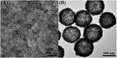
As shown in Scheme 1, AuPt-HNSs are obtained by etching the SiO2 spheres decorated with a porous AuPt shell. In this work, the hard-template (SiO2) is synthesized through a Stöber method. The well-dispersed SiO2 spheres have an average diameter of around 120 nm (Fig. S1†). They are subsequently functionalized with the amino groups of APTMS. Due to the electrostatic interaction between –NH2+ and AuCl4−/PtCl42−, the addition of reducing agent (AA) initiates the formation of Au-rich nuclei on the silica surface, thereby promoting the subsequent deposition of porous shells with the assistance of F127.The surface morphology and structure of the obtained AuPt-HNSs (after the removal of the SiO2 spheres) were investigated by scanning electron microscopy (SEM) and transmission electron microscopy (TEM). As revealed in Fig. 1A, monodispersed three-dimensional spheres are successfully obtained without any by-products. There are no serious cracks or collapses after the etching treatment, which confirms the effectiveness of this approach to obtain hollow structures.
The rough and dendritic surfaces indicate the existence of the porous shells. Pluronic F127 is a versatile structural directing agent used for the formation of nanoporous carbon and nanoporous/dendritic metals.13,19,20,24,26 A previous report has also demonstrated that AA is not only a common reducing agent but also favors the growth of branches.27 Guo et al. reported high-density Au/Pt hybrid nanoparticles supported on silica nanospheres by mixing pre-synthesized Au nanoparticles and amino-functionalized silica spheres. Then, the obtained composites were further mixed with platinum precursors in a boiling solution for 30 min.28 Compared to the previous approach, our synthetic method does not require any pre-synthesized Au seed or high-temperature operation. We can successfully achieve the one-step bimetallic coverage of silica support in a short time at room temperature.
After the removal of the silica templates, clear cavities and a uniform particle size (160 nm ± 10 nm) can be confirmed (Fig. 1B). The average wall thickness is about 20 nm. The high-resolution TEM (HRTEM) image of an individual particle shows the presence of well-defined dendritic shells (Fig. 2A) consisting of nanoparticles with a diameter of around 3 nm. Random assembly of such nanoparticles form interconnected branches in all directions, showing the porous shells. The porous shell can allow the smooth diffusion of guest species and sufficient contact with inner reactive sites. Fig. 2B shows a high resolution TEM image of the rectangular area marked in Fig. 2A. The lattice distance is 0.23 nm, which corresponds to the (111) plane of a face-centered cubic (fcc) AuPt crystal. Selected area electron diffraction (SAED) patterns confirm that the structure is polycrystalline, and the rings can be assigned to the (111), (200), (220), and (311) (Fig. S2†).
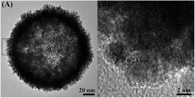 | ||
| Fig. 2 (A) Highly magnified TEM image of an individual hollow AuPt nanoparticle. (B) HRTEM image of the selected region in panel (A). | ||
The N2 adsorption–desorption isotherm shows a hysteresis loop at a relative pressure between 0.4 and 0.9, which is characteristic of a porous structure (Fig. S3†). The Brunauer–Emmett–Teller (BET) surface area of the AuPt-HNSs is calculated to be around 28.6 m2 g−1. This value is comparable with those of hyperbranched Pt nanostructure (15 m2 g−1),27 PdPd alloy nanosponges (19.04 m2 g−1)29 and porous Pt nanoballs (23 m2 g−1).30
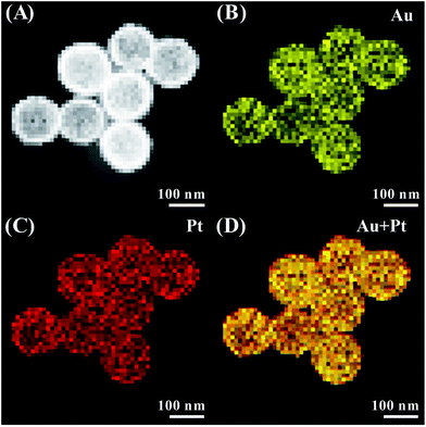
High-angle annular dark field scanning transmission electron microscopy (HAADF-STEM) was further used to characterize this unique architecture. The inner cavities are distinguished by the sharp contrast between the shells and hollow interiors (Fig. 3A). Elemental mapping (Fig. 3B–D) reveals the presence of element Au and Pt. Considering the reduction potentials of Pt and Au species, it is expected that the outer surface is predominantly occupied by Pt atoms. However, the resolution of the system cannot reveal such spatial distribution on the elemental mapping. The Au![[thin space (1/6-em)]](https://www.rsc.org/images/entities/char_2009.gif) :
:![[thin space (1/6-em)]](https://www.rsc.org/images/entities/char_2009.gif) Pt atomic ratio is close to 1
Pt atomic ratio is close to 1![[thin space (1/6-em)]](https://www.rsc.org/images/entities/char_2009.gif) :
:![[thin space (1/6-em)]](https://www.rsc.org/images/entities/char_2009.gif) 3, which is also confirmed by ICP analysis.
3, which is also confirmed by ICP analysis.
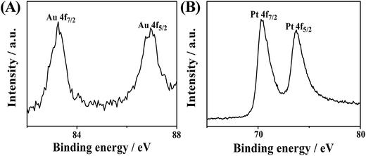
X-ray photoelectron spectroscopy (XPS) was also adopted to measure the elemental composition and the surface chemical states. Fig. 4 shows the Au 4f and Pt 4f doublets. The peaks of Au 4f7/2 and 4f5/2 at 83.25 and 87.10 eV are an indicator of the zerovalent state of Au. Similarly, the two peaks of Pt 4f7/2 (70.50 eV) and Pt 4f5/2 (73.75 eV) basically indicate the zerovalent state of Pt. No other visible peaks are present, which confirms the complete reduction of the metal species.8,31 The binding energies of Pt 4f7/2 and Pt 4f5/2 of AuPt-HNSs (Fig. 4) are shifted to lower values than those in commercial Pt/C catalyst (Fig. S4†), which is consistent with other reports.23,31 This shift implies the change in Pt electronic structure due to the formation of Au–Pt bonds, which is partly responsible for enhancing the electrocatalytic performance.
It is well-known that XPS can provide the composition of the surface, while ICP results refer to the bulk composition. The Pt![[thin space (1/6-em)]](https://www.rsc.org/images/entities/char_2009.gif) :
:![[thin space (1/6-em)]](https://www.rsc.org/images/entities/char_2009.gif) Au atomic ratio determined by XPS analysis is 91.6
Au atomic ratio determined by XPS analysis is 91.6![[thin space (1/6-em)]](https://www.rsc.org/images/entities/char_2009.gif) :
:![[thin space (1/6-em)]](https://www.rsc.org/images/entities/char_2009.gif) 8.4, which is much higher than the above ICP result. Since the reduction potential of Au(III) (+1.00 V vs. SHE) is much higher than Pt(II) (+0.76 V vs. SHE), it is anticipated that Au will form on the silica surface prior to Pt, leaving a Pt-rich outer surface.24
8.4, which is much higher than the above ICP result. Since the reduction potential of Au(III) (+1.00 V vs. SHE) is much higher than Pt(II) (+0.76 V vs. SHE), it is anticipated that Au will form on the silica surface prior to Pt, leaving a Pt-rich outer surface.24
To evaluate the catalytic properties of the as-prepared sample, ethylene glycol (EG) oxidation was selected. For comparison, commercial Pt/C (3–5 nm Pt nanoparticles (20 wt%) loaded on XC-72 carbon black) was also measured as a benchmark (Fig. S5†). Compared with methanol, direct ethylene glycol fuel cells (DEGFCs) exhibits notable advantages, such as a higher boiling point and a lower tendency to crossover from anode to cathode.9,32–34 It has been previously testified that the kinetic rate of EG oxidation and the corrosion of materials can be greatly improved in alkaline medium, but the transfer efficiency remains a challenging limitation to overcome.35 Thus it is still desirable to prepare efficient electrocatalysts for EG oxidation reaction. The specific electrochemical surface area (ECSA) of AuPt-HNSs is determined to be 20.1 m2 g−1 (Fig. S6†), which is higher than those of mesoporous Pt nanospheres (16.34 m2 g−1),36 PtAg nanotubes (18.2 m2 g−1),33 graphene-based porous Pt catalysts (11.86 m2 g−1),37 and Pt nanowire–Sn@CNT (17.2 m2 g−1).38
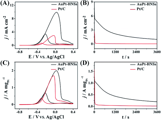
The surface specific activity (Fig. 5A) is a property intrinsic to a specific catalyst, whereas the mass specific activity (Fig. 5C) indicates the utilization efficiency during the catalytic reaction.39 In both cases, the typical EG oxidation cyclic voltammogram (CV) curves can be observed. The forward peak characteristic of the total oxidation for EG shows a higher current density (9.91 mA cm−2), which is 3.38 times higher than for Pt/C (2.93 mA cm−2). The mass activity of AuPt-HNSs is also higher than those of previously reported catalysts, as summarized in Table S1.† Although our AuPt-HNSs shows lower surface area compared to Pt/C (57.9 m2 g−1), the catalytic behavior of our sample toward EG oxidation exhibits an obvious advantage over the commercial Pt/C catalyst.
In addition, the If![[thin space (1/6-em)]](https://www.rsc.org/images/entities/char_2009.gif) :
:![[thin space (1/6-em)]](https://www.rsc.org/images/entities/char_2009.gif) Ib ratio (If and Ib are forward and backward current densities, Fig. 5C) is a strong indicator to evaluate the tolerance of a catalyst. The AuPt-HNSs have a higher ratio (2.97) than the hollow Pt54Cu23Co14 (2.5)9 or the Pt nanotubes (2.1).33 The current–time curves describe the tolerance of Pt-based catalysts to adsorbed carbonaceous intermediates during EG oxidation, as shown in Fig. 5B and D. At the early stage, all the current densities decay rapidly due to the accumulation of generated CO-like poisonous species. Both the starting and final current densities of AuPt-HNSs are superior to those of Pt/C, demonstrating an excellent tolerance over long periods of time.
Ib ratio (If and Ib are forward and backward current densities, Fig. 5C) is a strong indicator to evaluate the tolerance of a catalyst. The AuPt-HNSs have a higher ratio (2.97) than the hollow Pt54Cu23Co14 (2.5)9 or the Pt nanotubes (2.1).33 The current–time curves describe the tolerance of Pt-based catalysts to adsorbed carbonaceous intermediates during EG oxidation, as shown in Fig. 5B and D. At the early stage, all the current densities decay rapidly due to the accumulation of generated CO-like poisonous species. Both the starting and final current densities of AuPt-HNSs are superior to those of Pt/C, demonstrating an excellent tolerance over long periods of time.
After 3600 s, the catalysts were measured in the same electrolyte. The AuPt-HNSs maintain 93.4% of its initial current (Fig. S7A and C†) while the commercial Pt/C lost 29% of its initial current (Fig. S7B and D†). Due to the smaller size of the Pt nanoparticle (3–5 nm), the Pt/C exhibits a higher ECSA than that of the AuPt-HNSs. But, the small Pt nanoparticles in Pt/C are easily poisoned by the intermediate species adsorbed at the surface. From the above electrochemical results, it is concluded that the AuPt-HNSs shows promising potentials for future application in DEGFCs.
The improved electrocatalytic performance of the AuPt-HNSs possibly benefits from the following factors: (1) the porous shells are favorable for the diffusion of guest molecules, improving transport kinetics, (2) the hollow configuration can make the full use of the interior active sites and significantly increase the electrochemically active surface area, and (3) the synergistic effect between Au and Pt can contribute to high catalytic activity and good durability due to a better adsorption of hydroxyl groups and activation of poisoned surfaces.22,23
4. Conclusion
Here we present an effective and facile method to synthesize AuPt-HNSs with porous shells in high yield, based on a one-step bimetallic decoration of functionalized SiO2 spheres with the assistance of F127 and AA. The whole process does not involve any organic solvent or high temperature. The AuPt-HNSs demonstrate superior catalytic activity and durability toward EG oxidation relative to the commercial Pt/C in alkaline media. We strongly believe that our synthetic approach can be extended to prepare other Pt-based hollow electrocatalysts in the future.Acknowledgements
This work was supported by the National Natural Science Foundation of China (no. 21273218). Z. A. A. extends his sincere appreciation to the Deanship of Scientific Research at King Saud University for funding the Prolific Research Group (PRG-1436-04).References
- L. Au, X. Lu and Y. Xia, Adv. Mater., 2008, 20, 2517–2522 CrossRef CAS PubMed.
- E. Yan, Y. Ding, C. Chen, R. Li, Y. Hu and X. Jiang, Chem. Commun., 2009, 19, 2718–2720 RSC.
- N. Liu, H. Han, Z. Yuan and Z. Ma, RSC Adv., 2015, 5, 1867–1872 RSC.
- (a) J. Liu, Y. Wen, P. A. Aken, J. Maier and Y. Yu, Nano Lett., 2014, 14, 6387–6392 CrossRef CAS PubMed; (b) J. Liu, Z. Yang, J. Wang, L. Gu, J. Maier and Y. Yu, Nano Energy, 2015, 16, 389–398 CrossRef CAS; (c) J. Liu, P. Kopold, C. Wu, P. A. Aken, J. Maier and Y. Yu, Energy Environ. Sci., 2015, 8, 3531–3538 RSC.
- (a) K. Eid, H. Wang, V. Malgras, Z. Alothman, Y. Yamauchi and L. Wang, J. Phys. Chem. C, 2015, 119, 19947–19953 CrossRef CAS; (b) H. Wang, H. Jeong, M. Imura, L. Wang, L. Radhakrishnan, N. Fujita, T. Castle, O. Terasaki and Y. Yamauchi, J. Am. Chem. Soc., 2011, 133, 14526–14529 CrossRef CAS PubMed.
- X. Huang, Z. Zhao, L. Cao, Y. Chen, E. Zhu, Z. Lin, M. Li, A. Yan, A. Zettl, Y. M. Wang, X. Duan, T. Mueller and Y. Huang, Science, 2015, 348, 1230–1234 CrossRef CAS PubMed.
- (a) S. Park, D. Yoon, H. Baik and K. Lee, CrystEngComm, 2015, 17, 6852–6856 RSC; (b) H. Wang, S. Ishihara, K. Ariga and Y. Yamauchi, J. Am. Chem. Soc., 2012, 134, 10819–10821 CrossRef CAS PubMed; (c) H. Wang, L. Wang, T. Sato, Y. Sakamoto, S. Tominaka, K. Miyasaka, N. Miyamoto, Y. Nemoto, O. Terasaki and Y. Yamauchi, Chem. Mater., 2012, 24, 1591–1598 CrossRef CAS.
- H. M. Song, D. H. Anjum, R. Sougrat, M. N. Hedhili and N. M. Khashab, J. Mater. Chem., 2012, 22, 25003–25010 RSC.
- W. Hong, C. Shang, J. Wang and E. Wang, Nanoscale, 2015, 7, 9985–9989 RSC.
- S. Guo, Y. Fang, S. Dong and E. Wang, J. Phys. Chem. C, 2007, 111, 17104–17109 CAS.
- L. Dubau, J. Durst, F. Maillard, L. Guétaz, M. Chatenet, J. André and E. Rossinot, Electrochim. Acta, 2011, 56, 10658–10667 CrossRef CAS.
- X.-J. Liu, C.-H. Cui, H.-H. Li, Y. Lei, T.-T. Zhuang, M. Sun, M. N. Arshad, H. A. Albar, T. R. Sobahi and S.-H. Yu, Chem. Sci., 2015, 6, 3038–3043 RSC.
- L. Wang and Y. Yamauchi, J. Am. Chem. Soc., 2013, 135, 16762–16765 CrossRef CAS PubMed.
- F. Bai, Z. Sun, H. Wu, R. E. Haddad, X. Xiao and H. Fan, Nano Lett., 2011, 11, 3759–3762 CrossRef CAS PubMed.
- N. Fan, Y. Yang, W. Wang, L. Zhang, W. Chen, C. Zou and S. Huang, ACS Nano, 2012, 6, 4072–4082 CrossRef CAS PubMed.
- (a) Y. Sun, B. T. Mayers and Y. Xia, Nano Lett., 2002, 2, 481–485 CrossRef CAS; (b) W. Zhang, J. Yang and X. Lu, ACS Nano, 2012, 6, 7397–7405 CrossRef CAS PubMed.
- M. Yang, Q. Cai, C. Liu, R. Wu, D. Sun, Y. Chen, Y. Tang and T. Lu, J. Mater. Chem. A, 2014, 2, 13738–13743 CAS.
- P. Kundu, H. Heidari, S. Bals, N. Ravishankar and G. V. Tendeloo, Angew. Chem., Int. Ed., 2014, 53, 3970–3974 CrossRef CAS PubMed.
- H. Ataee-Esfahani, Y. Nemoto, L. Wang and Y. Yamauchi, Chem. Commun., 2011, 47, 3885–3887 RSC.
- H. Ataee-Esfahani, J. Liu, M. Hu, N. Miyamoto, S. Tominaka, K. C. W. Wu and Y. Yamauchi, Small, 2013, 9, 1047–1051 CrossRef CAS PubMed.
- A. A. Melvin, V. S. Joshi, D. C. Poudyal, D. Khushalani and S. K. Haram, ACS Appl. Mater. Interfaces, 2015, 7, 6590–6595 CAS.
- J. Zhang, K. Sasaki, E. Sutter and R. R. Adzic, Science, 2007, 315, 220–222 CrossRef CAS PubMed.
- (a) H.-P. Liang, T. G. J. Jones, N. S. Lawrence, L. Jiang and J. S. Barnard, J. Phys. Chem. C, 2008, 112, 4327–4332 CrossRef CAS; (b) J. Zeng, J. Yang, J. Y. Lee and W. Zhou, J. Phys. Chem. B, 2006, 110, 24606–24611 CrossRef CAS PubMed.
- H. Ataee-Esfahani, L. Wang, Y. Nemoto and Y. Yamauchi, Chem. Mater., 2010, 22, 6310–6318 CrossRef CAS.
- W. Li and A. M. Lane, Electrochem. Commun., 2011, 13, 913–916 CrossRef CAS.
- Y. Fang, D. Gu, Y. Zou, Z. Wu, F. Li, R. Che, Y. Deng, B. Tu and D. Zhao, Angew. Chem., Int. Ed., 2010, 49, 7987–7991 CrossRef CAS PubMed.
- L. Wang, C. Hu, Y. Nemoto, Y. Tateyama and Y. Yamauchi, Cryst. Growth Des., 2010, 10, 3454–3460 CAS.
- S. Guo, J. Zhai, Y. Fang, S. Dong and E. Wang, Chem.–Asian J., 2008, 3, 1156–1162 CrossRef CAS PubMed.
- C. Zhu, S. Guo and S. Dong, Chem.–Eur. J., 2013, 19, 1104–1111 CrossRef CAS PubMed.
- G. Surendran, L. Ramos, B. Pansu, E. Prouzet, P. Beaunier, F. Audonnet and H. Remita, Chem. Mater., 2007, 19, 5045–5048 CrossRef CAS.
- C. Li, H. Wang and Y. Yamauchi, Chem.–Eur. J., 2013, 19, 2242–2246 CrossRef CAS PubMed.
- A. Serov and C. Kwak, Appl. Catal., B, 2010, 97, 1–12 CrossRef CAS.
- Y. Kim, H. Kim and W. B. Kim, Electrochem. Commun., 2014, 46, 36–39 CrossRef CAS.
- W. Hong, C. Shang, J. Wang and E. Wang, Energy Environ. Sci., 2015, 8, 2910–2915 CAS.
- C. Jin, Y. Song and Z. Chen, Electrochim. Acta, 2009, 54, 4136–4140 CrossRef CAS.
- Y. Li, B. P. Bastakoti, V. Malgras, C. Li, J. Tang, J. H. Kim and Y. Yamauchi, Angew. Chem., Int. Ed., 2015, 54, 11073–11077 CrossRef CAS PubMed.
- L. Zhang, J.-J. Shao, W. Zhang, C. Zhang, X. Zheng, H. Du and Q.-H. Yang, J. Phys. Chem. C, 2014, 118, 25918–25923 CAS.
- S. Sun, G. Zhang, D. Geng, Y. Chen, M. N. Banis, R. Li, M. Cai and X. Sun, Chem.–Eur. J., 2010, 16, 829–835 CrossRef CAS PubMed.
- R. Chetty, S. Kundu, W. Xia, M. Bron, W. Schuhmann, V. Chirila, W. Brandl, T. Reinecke and M. Muhler, Electrochim. Acta, 2009, 54, 4208–4215 CrossRef CAS.
Footnote |
| † Electronic supplementary information (ESI) available. See DOI: 10.1039/c5ra24709h |
| This journal is © The Royal Society of Chemistry 2016 |


