Fabrication and characterization of ultra light SiC whiskers decorated by RuO2 nanoparticles as hybrid supercapacitors
Junhong Chen*a,
Yujie Zhangb,
Xinmei Hou*c,
Lei Su b,
Huili Fanb and
Kuo-Chih Chouc
aSchool of Materials Engineering, University of Science and Technology Beijing, Beijing 100083, China. E-mail: cjh@ustb.edu.cn
bSchool of Chemistry and Biological Engineering, University of Science and Technology Beijing, Beijing 100083, China
cState Key Laboratory of Advanced Metallurgy, University of Science and Technology Beijing, Beijing 100083, China. E-mail: houxinmei@ustb.edu.cn
First published on 9th February 2016
Abstract
Ultra light SiC whiskers decorated by RuO2 nanoparticles fabricated combining carbon thermal reduction and a hydrothermal route were investigated as novel hybrid supercapacitors with improved performance. The morphology and microstructure of the composite indicate that RuO2 nanoparticles are dispersed on the surface of SiC whiskers. The electrochemical behavior of the hybrid electrode systematically measured in 1.0 M H2SO4 demonstrates that SiC whiskers can considerably improve the supercapacitance properties of RuO2. The specific capacitance of RuO2 nanoparticles in the composite can be obtained as high as 1454.8 F g−1 with a mass ratio of RuO2/modified SiC whiskers of 2![[thin space (1/6-em)]](https://www.rsc.org/images/entities/char_2009.gif) :
:![[thin space (1/6-em)]](https://www.rsc.org/images/entities/char_2009.gif) 3. Moreover, the hybrid electrode displays a longer cycle life with a better capacitance retention (∼93.6%) than that of pure RuO2 after 2000 CV cycles.
3. Moreover, the hybrid electrode displays a longer cycle life with a better capacitance retention (∼93.6%) than that of pure RuO2 after 2000 CV cycles.
1. Introduction
In the face of ever-increasing energy consumption and global climate change, clean, as well as renewable energy storage in applications ranging from portable electronics and consumer electronics to large industrial equipment and aviation, has triggered tremendous research endeavors.1,2 Among various power source devices, supercapacitors that store energy through either ion adsorption (electrochemical double-layer capacitors, EDLCs) or fast surface redox reactions (pseudocapacitors), have been an attractive power solution due to their remarkable properties such as distinguished power output, high power density, noticeable reliability, fast charge–discharge rate and long cycle life.3–5Up to now, carbon with high specific surface6 and semiconductors with nanostructure, e.g., titanium dioxide (TiO2) nanotubes/nanowires, titanium nitride (TiN) nanowires, silicon nanowires and silicon carbide (SiC) nanowires7–9 are adopted as EDLCs. Especially cubic SiC (3C-SiC) exerts a widely fascination as EDLCs due to its excellent electronic conductivity of all SiC polytypes, the smallest band gap (∼2.4 eV) and the largest electron mobility (∼800 cm2 V−1 s−1 in a low-doped material).10 As for the materials as pseudocapacitors, metal oxides such as RuO2,11 MnO2,12 NiO,13 and Co3O4 (ref. 14) are usually adopted because they are capable of storing more charge during highly reversible redox reactions between metal oxides and adoptive electrolyte. Among these oxides, RuO2 has received extensive attention owing to its wide potential window, reversible redox reaction, high theoretical specific capacitance and high electrical conductivity (3 × 10² S cm−1).15 However the commercial application of RuO2 as electrode is limited due to the high cost of Ru. In addition, the phenomenon that RuO2 nanoparticles generally undergo grievous particle aggregation will result in poor cycling ability and deteriorative rate performance.
Aiming to improve the capacitive performances of supercapacitors, incorporating pseudocapacitance into EDLCs is a common method.6 For instance, Kim et al. applied microsphere SiC/nanoneedle manganese oxide composites as supercapacitor electrodes with the specific capacitance of 251.3 F g−1 at a scan rate of 10 mV s−1.16 Recently many investigators have attempted to combine RuO2 nanoparticles with low-cost materials including conducting polymers (polyaniline (PANI) and polypyrrole (PPy)),17 carbon activated carbons,18 carbon nanotubes (CNTs),19 carbon nanofibers20 and grapheme21 etc. to improve the rate capability of RuO2. The fabrication of hybrid electrode using various materials is still a hotspot for researchers.
In this work, a novel hybrid electrode as supercapacitors is proposed. The experimental idea is put forward as follows. First, large-scale ultra light SiC whiskers as EDLCs are synthesized using carbon thermal reduction method. Then RuO2 nanoparticles as pseudocapacitor are inlaid on the outer surface of SiC whiskers via a moderate hydrothermal route. The obtained RuO2/SiC whiskers composite was applied as hybrid electrode for supercapacitors for the first time, aiming to fabricate a novel hybrid electrode with enhanced electrochemical properties.
2. Experimental
2.1 Fabrication of RuO2/SiC whiskers composite
SiC whiskers were obtained via carbon thermal reduction using gangue (SiO2 > 99%) and carbon black as raw materials. The reaction was carried out at 1500 °C for 2 h at argon atmosphere and the detail has been reported in our previous work.22 For simplification, SiC whiskers are denoted as SiCw. SiCw was washed using 10% HF at ambient temperature for 1 h to remove silica and the resulting whiskers are symbolized as H-SiCw. The RuO2/H-SiCw composite was prepared as the following procedures: at first, 0.1 g H-SiCw was uniformly dispersed in 10 mL RuCl3 solution with continuous magnetical stirring. As for the influence of RuO2 with different content on the capacitances, the concentration of RuCl3 in 10 mL RuCl3 solution ranging from 0.0084 to 0.025 mol L−1 was adopted according to the theoretical mass ratio from 1![[thin space (1/6-em)]](https://www.rsc.org/images/entities/char_2009.gif) :
:![[thin space (1/6-em)]](https://www.rsc.org/images/entities/char_2009.gif) 3 to 1
3 to 1![[thin space (1/6-em)]](https://www.rsc.org/images/entities/char_2009.gif) :
:![[thin space (1/6-em)]](https://www.rsc.org/images/entities/char_2009.gif) 1 (RuO2/H-SiCw). Then 0.1 mol L−1 sodium hydroxide (NaOH) liquor was slowly dripped into the suspension to adjust the pH of the solution at ∼7. After reacting for 1 h, the solution was equably stirred in thermostatic oil bath and refluxed at 150 °C for 8 h, which could lead H-SiCw to fully contact with the solution. The resultant product was filtered and centrifuged several times with deionized water until the pH of the filtered water was ∼7. The obtained composite was dried at 80 °C for 12 h and denoted as RuO2/H-SiCw. In addition, pure RuO2 sample was prepared via the same way for comparison.
1 (RuO2/H-SiCw). Then 0.1 mol L−1 sodium hydroxide (NaOH) liquor was slowly dripped into the suspension to adjust the pH of the solution at ∼7. After reacting for 1 h, the solution was equably stirred in thermostatic oil bath and refluxed at 150 °C for 8 h, which could lead H-SiCw to fully contact with the solution. The resultant product was filtered and centrifuged several times with deionized water until the pH of the filtered water was ∼7. The obtained composite was dried at 80 °C for 12 h and denoted as RuO2/H-SiCw. In addition, pure RuO2 sample was prepared via the same way for comparison.
2.2 Preparation of supercapacitor electrode
The work electrode was prepared by mixing the above material respectively, i.e. H-SiCw, RuO2/H-SiCw or RuO2, and polyvinylidene fluoride (PVDF) with the mass ratio of 95![[thin space (1/6-em)]](https://www.rsc.org/images/entities/char_2009.gif) :
:![[thin space (1/6-em)]](https://www.rsc.org/images/entities/char_2009.gif) 5 in N-methyl-2-pyrrolidone (NMP). Then, the stable slurry was equably coated on a Ti sheet with the coating mass of about 3 mg (1 × 1 cm). The electrode was heated at 80 °C for 24 h to evaporate the solvent.
5 in N-methyl-2-pyrrolidone (NMP). Then, the stable slurry was equably coated on a Ti sheet with the coating mass of about 3 mg (1 × 1 cm). The electrode was heated at 80 °C for 24 h to evaporate the solvent.
2.3 Characterization and electrochemical measurement
X-ray diffraction (XRD) patterns of the samples were obtained on PW-1830 X-ray diffractometer (Philips) with Cu Kα from 10° to 80° (2θ) at a scanning speed of 1° min−1. X-ray photoelectron spectroscopy (XPS) measurements were performed on ESCALAB 250Xi (Thermo Fisher Scientific). The structure and morphology of the prepared samples were characterized using field-emission scanning electron microscopy (FE-SEM, FEI-SIRION, operated at 5 kV) and transmission electron microscopy (TEM) (Tecnai G2 F30 S-TWIN). The specific surface area was determined from the nitrogen adsorption–desorption isotherm measured at 77 K on a Quadrasorb SI-MP analyzer using Brunauer–Emmett–Teller (BET) model.The electrochemical behavior was investigated on a CHI660E electrochemical working station. A three-electrode system was adopted and the auxiliary and reference electrode were platinum foil and Ag/AgCl (KCl-saturated) respectively. The electrolyte used in all of the measurements was 1.0 M H2SO4 aqueous solution. Cyclic voltammetry (CV), galvanostatic charge/discharge characteristics and electrochemical impedance spectroscopy (EIS) were carried out. The potential range for CV tests was from 0 to 1 V and the scan rates were in the range from 5 to 500 mV s−1. Galvanostatic charge/discharge measurements were carried out from 0 to 1 V with different current densities at 0.2, 0.5, 1, 2, 5 and 8 A g−1. EIS measurements were done by applying an AC voltage with 5 mV amplitude in a frequency range from 0.1 Hz to 100 kHz.
3. Results and discussion
3.1 Phase and morphology characterization
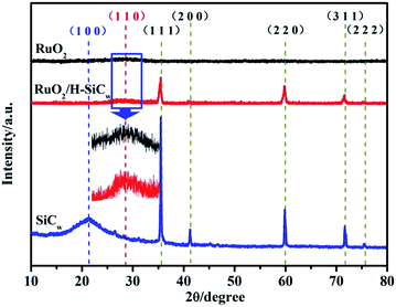
Fig. 1(a) shows the obtained product was grey whiskers in large scale. The whiskers were so lightweight that they could stably stand on the dandelion (Fig. 1(b)). XRD patterns of SiCw, RuO2/H-SiCw and RuO2 are shown in Fig. 2. For SiCw, the broad peak at about 20° corresponds to the amorphous silica shell. And the other five reflection peaks from 30 to 80° can be indexed to be the characteristic peaks of cubic SiC (β-SiC, card no. 01-073-1706). In view of the RuO2/H-SiCw composite, the characteristic peaks of β-SiC remain while the broad peak at about 20° disappears, indicating that silica is removed by HF. A weak broad peak at about 28° appears at high magnification, this corresponds to (1 1 0) of tetragonal RuO2, demonstrating the existence of amorphous RuO2 phase.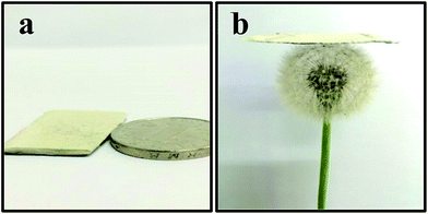 | ||
| Fig. 1 (a) Photograph of the as-received SiC whiskers and (b) the as-received SiC whiskers standing on the clover. | ||
To confirm the existent state of RuO2 in the RuO2/H-SiCw composite, the detailed surface information was examined using XPS as shown in Fig. 3. Survey spectrum indicates that the sample surface consists of Ru, O, Si and C (Fig. 3(a)). The Ru 3d core-level spectra (Fig. 3(b)) in RuO2/H-SiCw composite consist of two main peaks at about 280.7 and 284.8 eV, corresponding to the 5/2 and 3/2 spin–orbit components of Ru (3d) with spinorbit-splitting of about 4.1 eV. It is assigned to ruthenium oxide in RuO2.23 A doublet peak with binding energy (BE) at about 282.3 and 286.5 eV corresponds to RuO3. More critical information can be acquired by analysis of Ru 3p spectra to determine the accurate ruthenium oxidation state. One doublet at 462.5 and 484.7 eV of Ru 3p core-level spectrum corresponding to the spin–orbit splitting of Ru (3p) is observed in Fig. 3(c). This is consistent with the RuO2 chemical state.24
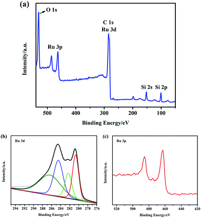 | ||
Fig. 3 (a) XPS wide scan survey spectra of RuO2/H-SiCw (2![[thin space (1/6-em)]](https://www.rsc.org/images/entities/char_2009.gif) : :![[thin space (1/6-em)]](https://www.rsc.org/images/entities/char_2009.gif) 3); (b) XPS spectra of Ru 3d peaks of RuO2/H-SiCw (2 3); (b) XPS spectra of Ru 3d peaks of RuO2/H-SiCw (2![[thin space (1/6-em)]](https://www.rsc.org/images/entities/char_2009.gif) : :![[thin space (1/6-em)]](https://www.rsc.org/images/entities/char_2009.gif) 3); (c) XPS spectra of Ru 3p peaks of RuO2/H-SiCw (2 : 3). 3); (c) XPS spectra of Ru 3p peaks of RuO2/H-SiCw (2 : 3). | ||
The structure and morphology of the obtained SiCw, H-SiCw, RuO2/H-SiCw and RuO2 were further characterized using FE-SEM and TEM techniques. SEM image of as-received SiCw is shown in Fig. 4(a), in which the as-received SiCw shows a straight filament with a smooth surface. TEM image clearly shows that SiCw before etching possesses SiC@SiO2 core–shell structure and the shell of SiO2 is characterized as a smooth thin layer (Fig. 4(b)). After etching by HF, the surface of H-SiCw becomes much coarser (Fig. 4(c)). TEM analysis indicates that SiO2 shell is removed and the surface after etching is rougher (Fig. 4(d)). As for the morphology of the RuO2/H-SiCw composite, the filament structure is still retained. However the surfaces become extremely rough and rugged due to the deposition of RuO2 nanoparticles on the surfaces. The typical morphology of RuO2/H-SiCw is shown in Fig. 4(e) and (f). It can be seen that RuO2 nanoparticles were attached uniformly on the surface of H-SiCw. Fig. 5 shows that the morphology of pure RuO2 nanoparticles prepared and the inset in Fig. 5 is the diffraction pattern of the selected area, which illustrates RuO2 is amorphous.
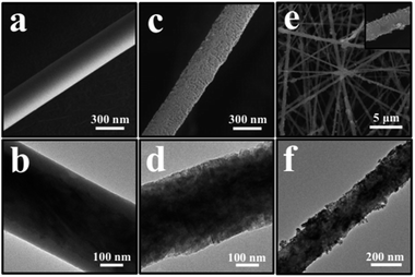 | ||
Fig. 4 FE-SEM images of the as-prepared SiCw (a), H-SiCw (c) and RuO2/H-SiCw (2![[thin space (1/6-em)]](https://www.rsc.org/images/entities/char_2009.gif) : :![[thin space (1/6-em)]](https://www.rsc.org/images/entities/char_2009.gif) 3) (e), respectively. TEM images of SiCw (b), H-SiCw (d) and RuO2/H-SiCw (2 3) (e), respectively. TEM images of SiCw (b), H-SiCw (d) and RuO2/H-SiCw (2![[thin space (1/6-em)]](https://www.rsc.org/images/entities/char_2009.gif) : :![[thin space (1/6-em)]](https://www.rsc.org/images/entities/char_2009.gif) 3) (f), respectively. 3) (f), respectively. | ||
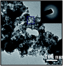 | ||
| Fig. 5 TEM image of pure RuO2 nanoparticles, the inset is corresponding SAED patterns of the marked region. | ||
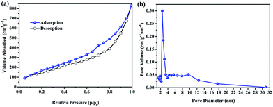
The specific surface area of H-SiCw is determined by the nitrogen adsorption–desorption isotherm as shown in Fig. 6. The BET model gives a specific surface area of 517 m2 g−1 (Fig. 6(a)). The pore diameter is mesopores ranging from 2 to 4 nm (Fig. 6(b)).
3.2 Electrochemical capacitive performance
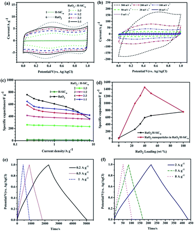
The electrochemical performances of resulting electrode for supercapacitors were tested using CV and galvanostatic charge/discharge with potential windows ranging from 0 to 1 V in 1.0 M H2SO4 electrolyte. In this work, Ti sheet was equably and completely coated by stable slurry. Therefore Ti sheet is not directly exposed to 1.0 M H2SO4 and is stable in 1.0 M H2SO4 electrolyte. In addition, there was no unusual phenomenon occurred at the surface of Ti sheet during the whole electrochemical measurement. Fig. 7(a) shows a comparison of the CV curves of H-SiCw, RuO2/H-SiCw with different RuO2/H-SiCw mass ratio and RuO2 electrodes at a scan rate of 10 mV s−1. All the CV plots display a typical capacitive behavior, i.e. quasi-rectangular shape. Such capacitive characteristics of H-SiCw electrode associate with the excellent electrical conductivity, large electroactive areas and electric double-layer capacity. For RuO2, a larger CV encircled area with a symmetric CV shape represents a higher pseudocapacitance and reversible redox reactions have taken place (Fig. 7(a)). In view of the RuO2/H-SiCw composite, the CV loop area increases with the content of RuO2 increasing (Fig. 7(a)). It should be pointed out that the CV curves of the RuO2/H-SiCw composite with the ratio of 2![[thin space (1/6-em)]](https://www.rsc.org/images/entities/char_2009.gif) :
:![[thin space (1/6-em)]](https://www.rsc.org/images/entities/char_2009.gif) 3 over a wider range of scan rates (Fig. 7(b)) exhibits the excellent power handling performance and the capacitive response could be maintained even at the scan rate as high as 500 mV s−1.
3 over a wider range of scan rates (Fig. 7(b)) exhibits the excellent power handling performance and the capacitive response could be maintained even at the scan rate as high as 500 mV s−1.
The specific capacitance of the electrode measured by the galvanostatic charge/discharge method can be estimated according to the following equation:25
 | (1) |
![[thin space (1/6-em)]](https://www.rsc.org/images/entities/char_2009.gif) :
:![[thin space (1/6-em)]](https://www.rsc.org/images/entities/char_2009.gif) 3, 1
3, 1![[thin space (1/6-em)]](https://www.rsc.org/images/entities/char_2009.gif) :
:![[thin space (1/6-em)]](https://www.rsc.org/images/entities/char_2009.gif) 2, 2
2, 2![[thin space (1/6-em)]](https://www.rsc.org/images/entities/char_2009.gif) :
:![[thin space (1/6-em)]](https://www.rsc.org/images/entities/char_2009.gif) 3 and 1
3 and 1![[thin space (1/6-em)]](https://www.rsc.org/images/entities/char_2009.gif) :
:![[thin space (1/6-em)]](https://www.rsc.org/images/entities/char_2009.gif) 1 against the current density are plotted in Fig. 7(c). It is clearly found that RuO2/H-SiCw composite possessed 649.2 F g−1 for RuO2/H-SiCw (1
1 against the current density are plotted in Fig. 7(c). It is clearly found that RuO2/H-SiCw composite possessed 649.2 F g−1 for RuO2/H-SiCw (1![[thin space (1/6-em)]](https://www.rsc.org/images/entities/char_2009.gif) :
:![[thin space (1/6-em)]](https://www.rsc.org/images/entities/char_2009.gif) 1), 591.9 F g−1 for RuO2/H-SiCw (2
1), 591.9 F g−1 for RuO2/H-SiCw (2![[thin space (1/6-em)]](https://www.rsc.org/images/entities/char_2009.gif) :
:![[thin space (1/6-em)]](https://www.rsc.org/images/entities/char_2009.gif) 3), 416.5 F g−1 for RuO2/H-SiCw (1
3), 416.5 F g−1 for RuO2/H-SiCw (1![[thin space (1/6-em)]](https://www.rsc.org/images/entities/char_2009.gif) :
:![[thin space (1/6-em)]](https://www.rsc.org/images/entities/char_2009.gif) 2) and 262.0 F g−1 for RuO2/H-SiCw (1
2) and 262.0 F g−1 for RuO2/H-SiCw (1![[thin space (1/6-em)]](https://www.rsc.org/images/entities/char_2009.gif) :
:![[thin space (1/6-em)]](https://www.rsc.org/images/entities/char_2009.gif) 3) at 0.2 A g−1. It should be pointed out that the capacitance of all electrodes gradually decreases with the current density increasing from 0.2 to 8 A g−1. The specific capacitance of pure RuO2 exhibits a rapid decrease when higher currents is applied (Fig. 7(c)). At higher current densities, it became hard to maintain the redox reactions completely at the inner active sites of the electrodes, leading to a reduction of the electrochemical performance of the electrodes. Furthermore, RuO2 as pseudocapacitive material, usually provide slower ion diffusions than EDLCs, which causes difficulty for RuO2 to continue appropriate redox reactions at higher current densities.26 By contrast, the hybrid electrode possesses a better rate performance than pure RuO2 due to the enhanced mechanical and chemical stability provided by the supporting material, i.e. SiCw, in sustaining the redox reactions at higher current densities.27
3) at 0.2 A g−1. It should be pointed out that the capacitance of all electrodes gradually decreases with the current density increasing from 0.2 to 8 A g−1. The specific capacitance of pure RuO2 exhibits a rapid decrease when higher currents is applied (Fig. 7(c)). At higher current densities, it became hard to maintain the redox reactions completely at the inner active sites of the electrodes, leading to a reduction of the electrochemical performance of the electrodes. Furthermore, RuO2 as pseudocapacitive material, usually provide slower ion diffusions than EDLCs, which causes difficulty for RuO2 to continue appropriate redox reactions at higher current densities.26 By contrast, the hybrid electrode possesses a better rate performance than pure RuO2 due to the enhanced mechanical and chemical stability provided by the supporting material, i.e. SiCw, in sustaining the redox reactions at higher current densities.27
Fig. 7(d) shows the specific capacitance of the samples as a function of RuO2 loading weight in the composites. The capacitance per RuO2 in the composite has been calculated according to the following equation:6
 | (2) |
![[thin space (1/6-em)]](https://www.rsc.org/images/entities/char_2009.gif) :
:![[thin space (1/6-em)]](https://www.rsc.org/images/entities/char_2009.gif) 3, which was ascribed to the optimized nanostructure with well-dispersed RuO2 nanoparticles as shown in Fig. 4. Thus the results hint that the composite could substantially improve the utilization and electrochemical capacitance properties of RuO2.
3, which was ascribed to the optimized nanostructure with well-dispersed RuO2 nanoparticles as shown in Fig. 4. Thus the results hint that the composite could substantially improve the utilization and electrochemical capacitance properties of RuO2.
For further evaluating the specific capability of the RuO2/H-SiCw (2![[thin space (1/6-em)]](https://www.rsc.org/images/entities/char_2009.gif) :
:![[thin space (1/6-em)]](https://www.rsc.org/images/entities/char_2009.gif) 3) composite, the galvanostatic charge/discharge curves were measured between 0 and 1 V at the current density of 0.2, 0.5, 1, 2, 5 and 8 A g−1 respectively (as shown in Fig. 7(e) and (f)). It is obvious that the charge curves are symmetric to their corresponding discharge counterparts, suggesting the occurrence of the reversible pseudocapacitive reaction. There are low voltage losses even when the current density is up to 8 A g−1. In addition, low internal resistances exist within electrode because of the tight insertion of RuO2 on the outer surface of H-SiCw and the rough surface of the composite. The phenomenon suggests that the composite electrode exhibits excellent capacitive performance by incorporating pseudocapacitors into EDLCs.
3) composite, the galvanostatic charge/discharge curves were measured between 0 and 1 V at the current density of 0.2, 0.5, 1, 2, 5 and 8 A g−1 respectively (as shown in Fig. 7(e) and (f)). It is obvious that the charge curves are symmetric to their corresponding discharge counterparts, suggesting the occurrence of the reversible pseudocapacitive reaction. There are low voltage losses even when the current density is up to 8 A g−1. In addition, low internal resistances exist within electrode because of the tight insertion of RuO2 on the outer surface of H-SiCw and the rough surface of the composite. The phenomenon suggests that the composite electrode exhibits excellent capacitive performance by incorporating pseudocapacitors into EDLCs.
EIS technique was also employed to investigate the conductive and diffusive behavior of the RuO2/H-SiCw (2![[thin space (1/6-em)]](https://www.rsc.org/images/entities/char_2009.gif) :
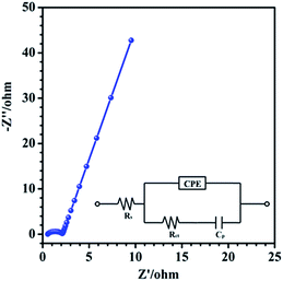
:![[thin space (1/6-em)]](https://www.rsc.org/images/entities/char_2009.gif) 3) electrode. It was carried out at a frequency range from 0.1 Hz to 100 kHz, where Z′ and Z′′ are the real and imaginary parts of the impedance, respectively (Fig. 8). The Nyquist plot consisted of a semicircle in the high-frequency region and a linear part in the low-frequency region. The equivalent circuit diagram (inset in Fig. 8) includes the solution resistance Rs, the charge transfer resistance Rct, a pseudocapacitive element Cp from redox process and the constant phase element (CPE) to account for the double layer capacitance. The linear region of the plot exhibits an angle between 45 and 90°, demonstrating an ideal capacitive behavior and low diffusion resistance.28 In the high-frequency region, Rs and Rct are measured to be 0.55 and 1.61 Ω respectively. Therefore the supercapacitor shows the low charge-transfer resistance and equivalent series resistance. This combines the properties of low diffusion and electron-transfer resistance and thus is responsible for the good electrochemical properties.
3) electrode. It was carried out at a frequency range from 0.1 Hz to 100 kHz, where Z′ and Z′′ are the real and imaginary parts of the impedance, respectively (Fig. 8). The Nyquist plot consisted of a semicircle in the high-frequency region and a linear part in the low-frequency region. The equivalent circuit diagram (inset in Fig. 8) includes the solution resistance Rs, the charge transfer resistance Rct, a pseudocapacitive element Cp from redox process and the constant phase element (CPE) to account for the double layer capacitance. The linear region of the plot exhibits an angle between 45 and 90°, demonstrating an ideal capacitive behavior and low diffusion resistance.28 In the high-frequency region, Rs and Rct are measured to be 0.55 and 1.61 Ω respectively. Therefore the supercapacitor shows the low charge-transfer resistance and equivalent series resistance. This combines the properties of low diffusion and electron-transfer resistance and thus is responsible for the good electrochemical properties.
The good electrochemical properties of RuO2/H-SiCw composite can be explained by the following factors. Firstly, β-SiC possesses the smallest band gap and the largest electron mobility among all SiC polytypes. Secondly, the surfactivity of SiCw is promoted by HF, which promotes the deposition of RuO2 and results in high connectivity between RuO2 and H-SiCw. During the charge/discharge process, RuO2 nanoparticles are beneficial to the formation of pores for ion-buffering reservoirs. Finally H-SiCw possesses the microstructure of long and straight filaments, which offers both electrical conductive channels and significant support for the deposition of RuO2. Thus this results in the perfect interfacial contact to facilitate the speed of electrons transport and enhance the mechanical and chemical stability. The mechanism of charge storage of RuO2 in 1.0 M H2SO4 (aq) may proceed via oxidization and reduction reactions as follows.
| RuO2 + 2H+ + 2e− (oxidized state) ↔ Ru(OH)2 (reduced state) |
As for the cycling performance, the cycling stabilities of RuO2/H-SiCw (2![[thin space (1/6-em)]](https://www.rsc.org/images/entities/char_2009.gif) :
:![[thin space (1/6-em)]](https://www.rsc.org/images/entities/char_2009.gif) 3) and RuO2 electrodes were measured with cyclic voltammetry at the scan rate of 10 mV s−1 as shown in Fig. 9. After 2000 continuous cycles, the capacitance retention for RuO2/H-SiCw (2
3) and RuO2 electrodes were measured with cyclic voltammetry at the scan rate of 10 mV s−1 as shown in Fig. 9. After 2000 continuous cycles, the capacitance retention for RuO2/H-SiCw (2![[thin space (1/6-em)]](https://www.rsc.org/images/entities/char_2009.gif) :
:![[thin space (1/6-em)]](https://www.rsc.org/images/entities/char_2009.gif) 3) and RuO2 electrode respectively attained 93.6% and 85.5% of the original capacitance under the same conditions. The pseudocapacitors such as RuO2 possess worse cycling performance due to particle aggregation. As for the hybrid electrode material of RuO2/H-SiCw, it is true that H-SiCw serves as conductive and supporting material. Besides that, it also acts as EDLC in hybrid materials. As for the state of RuO2 nanoparticles, it can be seen that RuO2 nanoparticles are attached uniformly on the surface of H-SiCw (Fig. 4(e) and f), therefore the maximum specific capacitance of RuO2 in the composite with the RuO2 to H-SiCw mass ratio of 2
3) and RuO2 electrode respectively attained 93.6% and 85.5% of the original capacitance under the same conditions. The pseudocapacitors such as RuO2 possess worse cycling performance due to particle aggregation. As for the hybrid electrode material of RuO2/H-SiCw, it is true that H-SiCw serves as conductive and supporting material. Besides that, it also acts as EDLC in hybrid materials. As for the state of RuO2 nanoparticles, it can be seen that RuO2 nanoparticles are attached uniformly on the surface of H-SiCw (Fig. 4(e) and f), therefore the maximum specific capacitance of RuO2 in the composite with the RuO2 to H-SiCw mass ratio of 2![[thin space (1/6-em)]](https://www.rsc.org/images/entities/char_2009.gif) :
:![[thin space (1/6-em)]](https://www.rsc.org/images/entities/char_2009.gif) 3 benefits from the optimized nanostructure with well-dispersed RuO2 nanoparticles. What's more, the positive role of H-SiCw for pinning nanosized RuO2 particles can effectively prevent the aggregation of the nanoparticles during electrochemical cycles, which is similar to that investigated in lithium storage systems29 and thus leads to better cycling performance. The degradation of hybrid electrode occurred mainly due to RuO2 nanoparticles breaking and collapsing detaching from H-SiCw upon repeated cycling, which can be inevitable.30,31 However, H-SiCw with outstanding mechanical and chemical stabilities, and high flexibility, can effectively prevent the aggregation of the nanoparticles and still play an important role in slowing down the degradation process.
3 benefits from the optimized nanostructure with well-dispersed RuO2 nanoparticles. What's more, the positive role of H-SiCw for pinning nanosized RuO2 particles can effectively prevent the aggregation of the nanoparticles during electrochemical cycles, which is similar to that investigated in lithium storage systems29 and thus leads to better cycling performance. The degradation of hybrid electrode occurred mainly due to RuO2 nanoparticles breaking and collapsing detaching from H-SiCw upon repeated cycling, which can be inevitable.30,31 However, H-SiCw with outstanding mechanical and chemical stabilities, and high flexibility, can effectively prevent the aggregation of the nanoparticles and still play an important role in slowing down the degradation process.
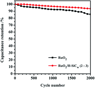 | ||
Fig. 9 Comparison of cycling performances measured at a scan rate of 10 mV s−1 for the bare RuO2 and RuO2/H-SiCw (2![[thin space (1/6-em)]](https://www.rsc.org/images/entities/char_2009.gif) : :![[thin space (1/6-em)]](https://www.rsc.org/images/entities/char_2009.gif) 3) composite. 3) composite. | ||
4. Conclusions
A kind of novel hybrid electrode for supercapacitors, i.e. RuO2/H-SiCw is fabricated combing carbon thermal reduction and hydrothermal route. The results reveal that the as-resultant composite nanostructures consist of RuO2 nanoparticles inlaid on the surfaces of H-SiCw. When the mass ratio of RuO2/H-SiCw is 2![[thin space (1/6-em)]](https://www.rsc.org/images/entities/char_2009.gif) :
:![[thin space (1/6-em)]](https://www.rsc.org/images/entities/char_2009.gif) 3, RuO2 nanoparticles in the composite achieve the specific capacitance values as high as 1454.8 F g−1. In addition, the as-prepared electrode exhibits a superb charge storage characteristic with large specific capacitance of 591.9 F g−1 at the current density of 0.2 A g−1. It also possesses a long circle life with a good capacitance retention (∼93.6%) after 2000 CV cycles owing to the combination of modified SiC whiskers as EDLC material and RuO2 as pseudocapacitive material. Our new approach suggests that the hybrid electrode of RuO2/H-SiCw possesses promising electrochemical performance as supercapacitors.
3, RuO2 nanoparticles in the composite achieve the specific capacitance values as high as 1454.8 F g−1. In addition, the as-prepared electrode exhibits a superb charge storage characteristic with large specific capacitance of 591.9 F g−1 at the current density of 0.2 A g−1. It also possesses a long circle life with a good capacitance retention (∼93.6%) after 2000 CV cycles owing to the combination of modified SiC whiskers as EDLC material and RuO2 as pseudocapacitive material. Our new approach suggests that the hybrid electrode of RuO2/H-SiCw possesses promising electrochemical performance as supercapacitors.
Acknowledgements
The authors express their appreciation to National Nature Science Foundation of China (No. 51172021 and 51572019), the National Science-technology Support Plan Projects (Grant 2013BAF09B01) and the National Science Fund for Excellent Young Scholars of China (No. 51522402) for financial support.Notes and references
- B. You, J. Jiang and S. Fan, ACS Appl. Mater. Interfaces, 2014, 6, 15302–15308 CAS.
- C. Liu, F. Li, L. Ma and H. Cheng, Adv. Mater., 2010, 22, E28–E62 CrossRef CAS PubMed.
- X. Yang, C. Cheng, Y. Wang, L. Qiu and D. Li, Science, 2013, 341, 534–537 CrossRef CAS PubMed.
- Y. Wang, J. Chen, J. Cao, Y. Liu, Y. Zhou, J. Ouyang and D. Jia, J. Power Sources, 2014, 271, 269–277 CrossRef CAS.
- X. Lu, G. Wang, T. Zhai, M. Yu, J. Gan, Y. Tong and Y. Li, Nano Lett., 2012, 12, 1690–1696 CrossRef CAS PubMed.
- T. Y. Kim, G. Jung, S. Yoo, K. S. Suh and R. S. Ruoff, ACS Nano, 2013, 7, 6899–6905 CrossRef CAS PubMed.
- Y. Xie, C. Xia, H. Du and W. Wang, J. Power Sources, 2015, 286, 561–570 CrossRef CAS.
- H. Zheng, T. Zhai, M. Yu, S. Xie, C. Liang, W. Zhao, S. C. I. Wang, Z. Zhang and X. Lu, J. Mater. Chem. C, 2013, 1, 225–229 RSC.
- J. P. Alper, M. Vincent, C. Carraro and R. Maboudian, Appl. Phys. Lett., 2012, 100, 163901–163904 CrossRef.
- J. B. Casady and R. W. Johnson, Solid-State Electron., 1996, 39, 1409–1422 CrossRef.
- H. Xia, M. Y. Shirley, G. Yuan, C. Cui and L. Lu, Electrochem. Solid-State Lett., 2012, 15, A60–A63 CrossRef CAS.
- H. A. Pan, O. Ghodbane, Y. T. Weng, H. S. Sheu, J. F. Lee, F. Favier and N. L. Wu, J. Electrochem. Soc., 2015, 162, A5106–A5114 CrossRef CAS.
- Y. Zhang, Y. Liu, Y. Guo, Y. X. Yeow, H. Duan, H. Li and H. Liu, Mater. Chem. Phys., 2015, 151, 160–166 CrossRef CAS.
- J. Xu, L. Gao, J. Cao, W. Wang and Z. Chen, Electrochim. Acta, 2010, 56, 732–736 CrossRef CAS.
- G. Wang, L. Zhang and J. Zhang, Chem. Soc. Rev., 2012, 41, 797–828 RSC.
- M. Kim and J. Kim, ACS Appl. Mater. Interfaces, 2014, 6, 9036–9045 CAS.
- J. Zang, S. Bao, C. M. Li, H. Bian, X. Cui, Q. Bao, C. Q. Sun, J. Guo and K. Lian, J. Phys. Chem. C, 2008, 112, 14843–14847 CAS.
- K. S. Yang, C. H. Kim and B. Kim, Electrochim. Acta, 2015, 174, 290–296 CrossRef CAS.
- R. Bi, X. Wu, F. Cao, L. Jiang, Y. Guo and L. Wan, J. Phys. Chem. C, 2010, 114, 2448–2451 CAS.
- R. Vellacheri, V. K. Pillai and S. Kurungot, Nanoscale, 2012, 4, 890–896 RSC.
- C. Zhang, H. Zhou, X. Yu, D. Shan, T. Ye, Z. Huang and Y. Kuang, RSC Adv., 2014, 4, 11197–11205 RSC.
- J. Chen, W. Liu, T. Yang, B. Li, J. Su, X. Hou and K. Chou, Cryst. Growth Des., 2014, 14, 4624–4630 CAS.
- A. Salomonsson, R. M. Petoral, K. Uvdal, C. Aulin, P. Käll, L. Ojamäe, M. Strand, M. Sanati and A. L. Spetz, J. Nanopart. Res., 2006, 8, 899–910 CrossRef CAS.
- P. Wang, H. Liu, Q. Tan and J. Yang, RSC Adv., 2014, 4, 42839–42845 RSC.
- D. Zhang, X. Zhang, Y. Chen, P. Yu, C. Wang and Y. Ma, J. Power Sources, 2011, 196, 5990–5996 CrossRef CAS.
- Z. S. Wu, D. W. Wang, W. Ren, J. Zhao, G. Zhou, F. Li and H. M. Cheng, Adv. Funct. Mater., 2010, 20, 3595–3602 CrossRef CAS.
- M. Kim, C. Lee and J. Jang, Adv. Funct. Mater., 2014, 24, 2489–2499 CrossRef CAS.
- Z. Li, Y. Mi, X. Liu, S. Liu, S. Yang and J. Wang, J. Mater. Chem., 2011, 21, 14706–14711 RSC.
- H. Li, L. Shi, Q. Wang, L. Chen and X. Huang, Solid State Ionics, 2002, 148, 247–258 CrossRef CAS.
- L. M. Huang, H. Z. Lin, T. C. Wen and A. Gopalan, Electrochim. Acta, 2006, 52, 1058–1063 CrossRef CAS.
- Z. S. Wu, D. W. Wang, W. Ren, J. Zhao, G. Zhou, F. Li and H. M. Cheng, Adv. Funct. Mater., 2010, 20, 3595–3602 CrossRef CAS.
| This journal is © The Royal Society of Chemistry 2016 |

