Structure-controllable superhydrophobic Cu meshes for effective separation of oils with different viscosities and aqueous pollutant purification†
Stephen Boakye-Ansaha,
Yong Taek Lima,
Ha-Jin Lee*b and
Won San Choi*a
aDepartment of Chemical and Biological Engineering, Hanbat National University, 125 Dongseodae-ro, Yuseong-gu, Daejeon, 34158, Republic of Korea. E-mail: choiws@hanbat.ac.kr; Fax: +82-42-821-1692; Tel: +82-42-821-1540
bWestern Seoul Center, Korea Basic Science Institute, 150 Bugahyun-ro, Seoudaemun-gu, Seoul, 03759, Republic of Korea. E-mail: hajinlee@kbsi.re.kr
First published on 5th February 2016
Abstract
Micropothole-based oxidized (MPO) Cu meshes with various surface morphologies, such as needle-like (NL), hair-like (HL), arch-like (AL), and pine needle-like (PNL) structures, were prepared by controlling the pH and temperature of the oxidation reaction solution. The separation efficiencies of 1H,1H,2H,2H-perfluorooctyltriethoxysilane (PFTOS)-coated MPO-Cu meshes were found to be 96–99% for oil/water separation, and the meshes maintained this performance over 20 separation cycles without deterioration. The HL mesh with long and flexible structures was outstanding for the separation of low viscosity oils, while the NL mesh with short and rigid structures was optimal for the separation of highly viscous oils. Double-layered meshes consisting of photocatalytic and superhydrophobic meshes exhibited high catalytic performance after the oil/water separation, demonstrating purification of an aqueous pollutant separated from the oil/water mixture.
1. Introduction
Over the years, catastrophic oil spills have ravaged our marine ecosystem. Because the destruction of the ecosystem by oil spills has deleterious effects on humans in the long term, scientists have developed appropriate technologies that can efficiently separate oil from water. Recently, various types of superhydrophobic materials, such as polymer membranes/fabrics,1,2 metal meshes,3–8 and sponges,9,10 have been reported for oil/water separation. These materials are generally prepared by the fabrication of surfaces with superhydrophobicity and superoleophilicity.17,18 Various types of oils, such as hexane, toluene, chloroform, dichloromethane, soybean oil, paraffin oil, silicone oil, and diesel oil, are used for testing the efficacy of oil/water separation. Various hierarchical structures with large water contact angles have been proposed for enhancing the separation efficiency or the flux capacity of these oils.11–16 However, the study of oil/water separation that considers the characteristics of low and high viscosity oils has not yet been reported. Meanwhile, most efforts have reported methods that focus on the separation itself of oils from oil/water mixtures rather than on the purification of pollutants that remain in the water after the oil/water separation. Extensive researches are necessary for simultaneous oil/water separation and pollutant purification because relatively little attention has been devoted to the purification of aqueous pollutants separated from oil/water mixtures.4–7Visible light-driven silver@silver halide (Ag@AgX) photocatalysts have recently received significant attention due to their stability and high photocatalytic activity.19–24 In particular, the silver@silver bromide (Ag@AgBr) catalyst is more efficient than the silver@silver chloride (Ag@AgCl) catalyst because Br− recombines with the photogenerated hole faster than Cl−.19 The Lin Feng group has recently reported on the purification of pollutants, which persist after the oil/water separation, using UV light-driven catalysts.4 Visible light comprises 43% of sunlight, while ultraviolet accounts for only 4%. In terms of effectively using sunlight, visible light-driven photocatalysts are more advantageous than those activated by ultraviolet light. Herein, we report on the visible light-driven purification of aqueous pollutants after oil/water separation and investigate the relationship between the surface morphologies of meshes and the viscosities of oils for effective separation.
2. Results and discussion
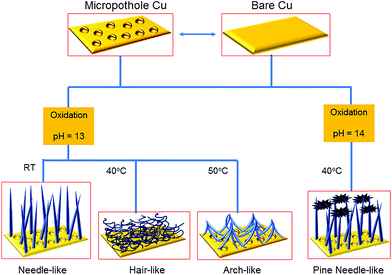
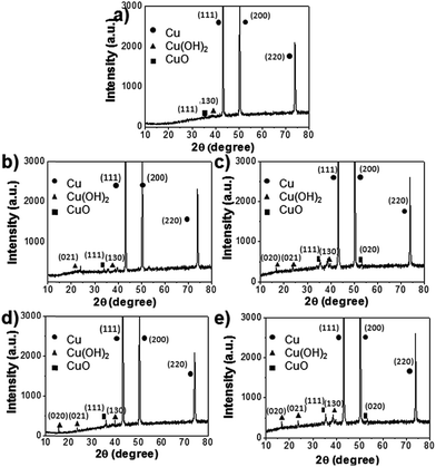
Fig. 1 shows a schematic of the synthesis of hierarchically oxidized Cu meshes (Cu mesh/CuO–Cu(OH)2) with various surface morphologies, which were prepared in either the presence or absence of micropotholes formed on a Cu mesh. Micropothole structures were formed by pre-etching a Cu mesh using HNO3. After pre-etching, an additional oxidation step was performed to prepare a hierarchically oxidized Cu mesh. Various types of hierarchically oxidized Cu meshes, including those with needle-like (NL), hair-like (HL), arch-like (AL), and pine needle-like (PNL) structures, were prepared by controlling the reaction pH and temperature, as well as the surface morphology of the Cu mesh template. The abilities of different Cu meshes to separate oil from water were then compared.The compositional variation of the Cu mesh after the pre-etching and oxidation steps was investigated by X-ray diffraction (XRD). The XRD pattern of the Cu mesh after pre-etching (Cu mesh with micropotholes) shows three strong peaks and several weak peaks associated with pristine Cu and CuO–Cu(OH)2, respectively (Fig. 2a). After treatment with a chemical oxidant, the Cu mesh with micropotholes was further oxidized into Cu(OH)2 and CuO. The oxidation mechanism of the Cu mesh using ammonium persulfate (APS) and NaOH is depicted in eqn (1).25 The product of eqn (1), Cu(OH)2, can be transformed into the more stable CuO (eqn (2)).26
| Cu + 4NaOH + (NH)4S2O8 → Cu(OH)2 + 2Na2SO4 + 2NH3 + 2H2O | (1) |
| Cu(OH)2 + 2OH− → Cu(OH)42− ↔ CuO + 2OH− + H2O | (2) |
Consequently, after oxidation, the intensities of peaks that are characteristic of Cu(OH)2 and CuO increased for all investigated mesh morphologies (Fig. 2b–e). These results suggest that the pristine Cu mesh can be transformed into Cu(OH)2 and CuO by pre-etching and a simple oxidation.
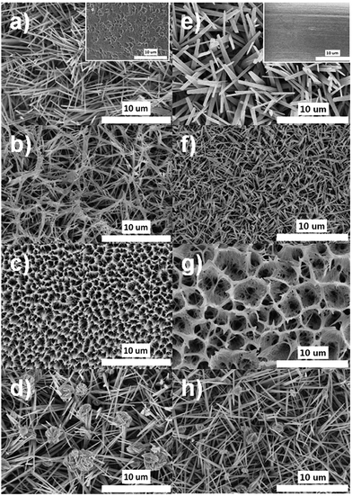
To investigate the effect of the surface morphology on the formation of the hierarchically oxidized Cu mesh, two types of templates were used: a pre-etched Cu mesh (micropotholes) and a pristine Cu mesh. The inset of Fig. 3a shows a scanning electron microscopy (SEM) image of the pre-etched Cu mesh, which indicates deep, randomly situated, and round micropotholes. Hierarchically oxidized Cu meshes (Cu mesh/CuO–Cu(OH)2) exhibiting different surface morphologies were formed using a pre-etched Cu mesh as a template at high pH (Fig. 3a–d). Below pH 12, irregular or indistinguishable structures were formed on the Cu mesh (data not shown). At pH 13, hierarchically oxidized structures with NL, HL, and AL morphologies were generated at reaction temperatures of R.T., 40 °C, and 50 °C, respectively, which reveals the temperature sensitivity of the surface morphologies of the Cu mesh at this pH (Fig. 3a–c). Low magnification SEM images of each morphology are displayed in Fig. S1.† It is interesting that the rigid-rod structure, such as the NL morphology, was produced at R.T., while flexible and slender structures, such as the HL morphology, were formed at 40 °C (Fig. 3a and b). An increase in reaction time resulted in the growth of long rigid-rod Cu(OH)2 structures, while an increase in reaction temperature disrupted the rigid rod-like growth and induced a flexible strand-like growth of Cu(OH)2 (Fig. S2†). Considering these results, it is possible that NL features combined to form the HL morphology and then produced AL structures as a function of increasing temperature. At temperatures greater than 50 °C, no significant change in surface morphology was observed, and the AL structures were maintained. At pH 14, only the PNL structures were observed over a broad temperature range (R.T. to 50 °C). Fig. 3d is representative of the PNL-structured Cu mesh prepared at 40 °C and pH 14. With an increase in pH, there is an increase in the concentration of OH−, which is a nucleophile that disrupts the growth of Cu(OH)2 strands to yield unstable Cu(OH)42− complex species. This complex is easily transformed into the more stable CuO by the release of H2O and OH−, as described in eqn (2).25 The reaction time was fixed at 30 minutes for all cases. Further increases in the reaction time over 50 minutes resulted in the loss of hierarchically oxidized Cu morphologies and the growth of irregular structures (Fig. S3†). Analogous surface morphologies (i.e., NL, HL, AL, and PNL structures) formed on Cu meshes when the pristine Cu without micropothole structures was used as a template (Fig. 3e–h). However, the micropothole-based oxidized (MPO) Cu meshes showed more complicated and fine-tuned structures than the non-micropothole-based oxidized (NMPO) Cu meshes. These results led us to compare the capabilities of these different structures to trap air because a significant increase in trapped-air can boost the superhydrophobicity.
To compare the air trapping capabilities of MPO- and NMPO-Cu meshes, their water contact angles (WCA) were measured. The wettability of a surface is closely related to its chemical composition and its surface roughness, and the four examined morphologies of MPO-Cu meshes maintain hierarchical structures with high specific surface areas. For low surface energy coating, 1H,1H,2H,2H-perfluorooctyltriethoxysilane (PFTOS) was used due to its ability to produce a thin and stable layer coating on the nanostructures. Other coating materials such as polydimethylsiloxane, octadecyltrimethoxysilane, and dodecyltriethoxysilane were unsuitable for our nanostructures. Before applying the hydrophobic coating, the MPO-Cu meshes exhibited very low WCAs close to 0° due to the hydrophilic nature of the oxidized Cu surface. After coating with the PFTOS, the WCAs of the MPO-Cu meshes promptly increased and then reached a steady-state value between 120° and 130° (Fig. 4a). Before annealing, the PFTOS covers and hides the surface morphology of the MPO-Cu mesh (Fig. S4†). After annealing, however, the needle-like structures of the MPO-Cu mesh appeared. After annealing at 100 °C, the WCAs of PFTOS-coated MPO-Cu meshes further increased to approximately 160°. These observations suggest that PFTOS can be evenly distributed over their surfaces by an annealing process and it leads to the increase in the WCAs. The WCAs of PFTOS-coated NMPO-Cu meshes were also measured and compared with those of the PFTOS-coated MPO-Cu meshes (Fig. 4b). The MPO-Cu meshes showed an approximately 10° higher water contact angle (WCA) than the NMPO-Cu meshes. Therefore, the presence of micropotholes induces more hierarchical structures on the oxidized Cu mesh, leading to an increase in the amount of trapped air within the structures and significantly contributing to the enhancement of the WCA.
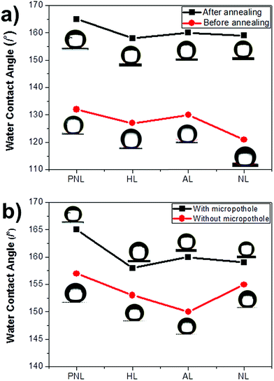 | ||
| Fig. 4 Water contact angle (WCA) data of the Cu mesh/CuO–Cu(OH)2/PFTOS with various types of surface morphologies in the presence and absence of (a) annealing or (b) micropotholes. | ||
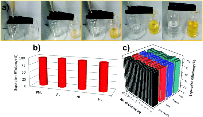
MPO-Cu meshes, after hydrophobic coating, were used for gravity-driven oil/water separation, which was facilitated by the robust superhydrophobicity of the structured surfaces. Fig. 5a shows representative photographs of the oil/water separation test using the PFTOS-coated MPO-Cu mesh, clearly exhibiting initial, intermediate, and final steps of oil/water separation. A mixture of hexane and water dyed with methylene orange (MO) was poured onto the PFTOS-coated MPO-Cu meshes (NL, HL, AL, and PNL structures). Because of the superhydrophobic property of the meshes, the hexane quickly permeated through the meshes and dropped into the container below, while the water dyed with MO flowed into a separate container through the meshes. No visible oil or water was observed in the collected water or oil, respectively, and the separation efficiencies of the PFTOS-coated MPO-Cu meshes were found to be 96–99% for the first oil/water separation test (Fig. 5b). The four types of mesh structures all showed similar separation efficiencies. The recycling ability of the meshes for use in oil/water separation was also investigated. After the first separation of the hexane/water mixture, the PFTOS-coated MPO-Cu meshes were thoroughly washed with ethanol and then reused for the same separation. The meshes retained hexane/water separation efficiencies of 96–99% over 20 separation cycles (Fig. 5c).
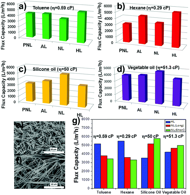
The oil separation capacities (fluxes) of the PFTOS-coated MPO-Cu meshes with NL, HL, AL, and PNL structures were investigated using various oils with different viscosities. The calculated fluxes for the HL mesh were 5180 L m−2 h−1 for toluene (η = 0.59 cP) and 5475 L m−2 h−1 for hexane (viscosity, η = 0.29 cP), which represent the highest capacities of the four different structures (Fig. 6a and b). In contrast, the fluxes for the NL mesh were 5160 L m−2 h−1 for silicone oil (μ = 50 cP) and 4640 L m−2 h−1 for vegetable oil (μ = 51.3 cP), which were the highest obtained capacities of the four different structures (Fig. 6c and d). The HL mesh, consisting of relatively long and flexible strands, showed outstanding performance for separating oils with low viscosity, while the NL mesh, composed of short and rigid rods, exhibited good action for oils with high viscosity. The WCAs for the HL and NL meshes were 158° and 159°, respectively, which were very similar to each other (Fig. 4a). Although the PNL and AL meshes possessed higher WCAs than the HL and NL meshes, they showed lower fluxes for test fluids with both low and high viscosities (Fig. 4a and 6a–d). This means that factors other than the WCA influence the flux of oils through these structures. It was speculated that the different oil fluxes observed for the HL and NL meshes could be attributed to the opposing aspects of their surface morphologies, i.e., long/flexible and short/rigid (Fig. 6a–d). To further investigate factors that affect the oil flux, a NL mesh with relatively short needles was prepared and tested for the separation of oils with low and high viscosities (Fig. 6e–g). The short-needled NL mesh exhibited the highest performance of all the types of meshes for high viscosity oils, such as silicone and vegetable oils, but it exhibited the lowest flux for low viscosity oils (Fig. 6g). The reason for the opposite performances observed after using the different surface morphologies could be attributed to the path-length of oil within the mesh during separation. Since the flow of high viscosity fluids is more affected by complexity of channel structures than that of low viscosity fluids due to the resistance of fluids to the channel,27 longer path-length of the HL mesh can retard penetration of high viscosity oils. However, high viscosity oils can relatively quickly penetrate through the NL mesh because the path-length of the NL mesh is relatively shorter than that of the HL mesh. On the other hand, the flow of low viscosity oils could be affected by other reasons rather than the complexity of channel structures as mentioned above. These results suggest that long and flexible structures are preferable for the separation of low viscosity oils, while short and rigid structures are good for the separation of high viscosity oils. In other words, a certain type of mesh surface morphology should be chosen for the separation of oils with different viscosities. We expect that our NL mesh, with a short and rigid needle-shaped morphology, holds promise for the separation of highly viscous oils.
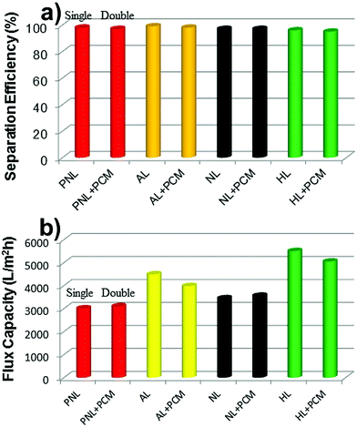
The separation efficiencies and the flux capacities of double-layered meshes consisting of the superhydrophobic mesh (each mesh/PFTOS) and the photocatalytic mesh (PCM:MPO-Cu mesh/Pdop/Ag/AgBr) were also tested (Fig. 7). PNL, AL, NL, or HL mesh was used as each mesh. The separation efficiencies of the double-layered meshes were found to be 95–98%, which were almost similar with the values (96–99%) of the single mesh (each mesh/PFTOS) for the oil/water separation test (Fig. 7a). The flux capacities of the double-layered meshes were a bit higher and lower than those of the single mesh (each mesh/PFTOS) (Fig. 7b). These results suggest that the double-layered meshes still maintain the high performance for oil/water separation.
The chemical and mechanical stabilities of the PFTOS-coated PNL mesh, which shows the highest WCA, were tested by measuring variations in the WCA after exposing the PNL mesh to different conditions for periods of 12 h. Under various chemical conditions (i.e., at different pH and in the presence of salt, NaCl), the WCAs of the PNL mesh changed slightly, but they remained above 150°, suggesting that the superhydrophobicity is robust against corrosive environments (Fig. 8a and b). The thermal stability of the NPL mesh was also tested by subjecting the mesh to elevated temperatures for 12 h, and the mesh maintained its superhydrophobicity with a WCA above 150° for all temperatures examined (Fig. 8c). For the mechanical abrasion test, the sandpaper with a load (520 g) was directly contacted on the superhydrophobic mesh (4 × 10⁻² m2). The sample was dragged over a 0.3 m distance with a pull speed of 0.1 m s−1, with horizontally directional movements. In the mechanical abrasion test, the PNL mesh maintained its superhydrophobicity for 6 abrasion cycles, after which the WCA decreased to approximately 140°, therefore indicating a good resistance to mechanical abrasion (Fig. 8d).
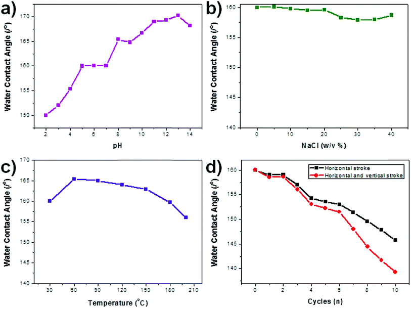 | ||
| Fig. 8 WCA data of a selected PFTOS-coated PNL mesh under various stimuli: (a) pH, (b) salt, (c) heat, and (d) mechanical abrasion. | ||
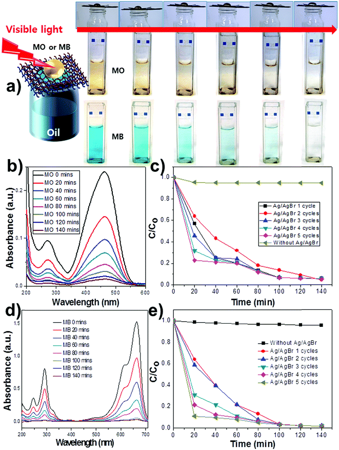
To investigate the possibility of purifying aqueous pollutants separated from the oil/water mixture, we coated the MPO-Cu mesh with polydopamine (Pdop) and Ag/AgBr to test its visible-light driven photocatalytic activity. The Pdop layer was used as a matrix for synthesizing the Ag/AgBr photocatalyst on the MPO-Cu mesh (Fig. S5a†). After synthesizing AgBr on top of a Pdop-coated MPO-Cu mesh (denoted as MPO-Cu mesh/Pdop), the surface of the MPO-Cu mesh/Pdop was further covered with AgBr structures (Fig. S5b†). Generally, AgBr can be partially reduced to Ag by weak reduction agents, such as the amine and imine functional groups in Pdop,28 resulting in the formation of Ag/AgBr (MPO-Cu mesh/Pdop/Ag/AgBr). The synthesis of Ag/AgBr was confirmed by energy dispersive X-ray spectroscopy (EDX) and X-ray diffraction (XRD) (Fig. S5c and S6†). We designed double-layered meshes (4.5 × 4.5 cm2) for oil/water separation and purification. The photocatalytic mesh was overlapped on the superhydrophobic mesh to serve a dual purpose of oil/water separation and pollutant purification (Fig. 9a). The upper Cu mesh was coated with Ag/AgBr photocatalysts, leading to a hydrophilic mesh (MPO-Cu mesh/Pdop/Ag/AgBr), while the lower mesh was superhydrophobic (HL mesh/PFTOS). Here, we used the MPO-Cu mesh with the HL structure, which exhibits the highest flux capacity for hexane of the four different structures examined. Fig. 9a shows the purification process for aqueous pollutants separated from the mixture of hexane and aqueous MO solution using the double-layered Cu meshes. Hexane quickly flowed through the upper and lower Cu meshes into a beaker below, while the aqueous MO solution remained on top of the Cu meshes. When the visible light source (300 W Xe lamp) irradiated the MO solution, the colour gradually faded because of the catalytic reaction between MO and Ag/AgBr on the upper Cu mesh (Fig. 9a). The UV-vis absorbance of the MO solution remarkably and gradually decreased as a function of increasing irradiation time, reflecting the degradation of the dye (Fig. 9b). In contrast, based on the calculation of the UV-vis absorption difference, only 9% of the MO dye degraded over 140 min in the absence of photocatalysts (Fig. S7a†). The lifetime of the MPO-Cu mesh/Pdop/Ag/AgBr was tested to verify that the high catalytic performance was retained (Fig. 9c). It was observed that MO molecules rapidly decomposed for five cycles without a deterioration in the catalytic activity of the treated mesh. Interestingly, the catalytic performance enhanced on the third use, compared with the activity of the first two uses, which suggests that the Ag/AgBr catalysts are further synthesized from the AgBr on the MPO-Cu mesh by means of visible light irradiation (Fig. 9c and S7†). A test for degradation of another pollutant such as a methylene blue (MB) was performed. The MB was effectively degraded as a function of increasing irradiation time only in the presence of photocatalysts (Fig. 9d and S8†). Interestingly, the catalytic performance gradually increased upon reuse test, compared with the activity of the first use, as observed in the MO test (Fig. 9e). Reuse test results of the MO and the MB suggest that the AgBr was incompletely reduced to Ag by weak reduction agents, such as the amine and imine functional groups in Pdop, which can be further reduced into the Ag/AgBr catalysts during the reuse by visible light irradiation. It leads to enhancement of catalytic performances upon reuse. The above results demonstrate that a variety of aqueous pollutants remaining after an oil/water separation can be purified by photocatalytic Cu meshes that are capable of multiple uses.
3. Conclusions
The micropothole-based oxidized (MPO) Cu meshes with various surface morphologies were prepared by controlling the pH and temperature of the oxidation reaction solution. Micropothole structures further induced the formation of hierarchical structures on the oxidized Cu mesh, which led to an increase in the amount of trapped air in the mesh. As a consequence, the trapped air significantly contributed to the enhancement of the WCA. The separation efficiencies of the PFTOS-coated MPO-Cu meshes were found to be 96–99% for oil/water separation, and the meshes operated for 20 separation cycles without deterioration. The HL mesh with its long and flexible structures was outstanding for the separation of low viscosity oils, while the NL mesh possessing short and rigid structures was better suited for the separation of high viscosity oils. This suggests that the separation of oils with different viscosities requires the selection of a specific mesh surface morphology. Furthermore, double-layered meshes, consisting of photocatalytic and superhydrophobic meshes, exhibited high catalytic performance after the oil/water separation and demonstrated the removal of an aqueous pollutant separated from the oil/water mixture.4. Experimental
Materials
Hydrochloric acid (HCl, >35%), nitric acid (HNO3, 70%) and acetone were purchased from Duksan pure chemicals. Ammonium persulfate ((NH4)2S2O8, 99.99%), potassium persulfate (K2S2O8, 98%), 1H,1H,2H,2H-perfluorooctyltriethoxysilane (PFTOS, 98%), dopamine hydrochloride, tris(hydroxymethyl)aminoethane (99.8%), sodium chloride (NaCl), sodium hydroxide (NaOH), sodium bromide (NaBr, 99.5%), silver nitrate (AgNO3, 99%), methylene blue (MB) and methylene orange (MO) were all purchased from Sigma-Aldrich and were used as-received without further purification. Deionized water (DI) with a resistivity of 18.2 MΩ cm was obtained using a Millipore Simplicity 185 system. Copper mesh and vegetable oil were purchased from a local market.Preparation of the superhydrophobic template (PFTOS-coated MPO-Cu meshes)
A pristine Cu mesh was sonicated in 0.1 M HCl/acetone/EtOH/DI water, sequentially and for 5 min each, to remove organic contaminants and surface oxide layers. After rinsing 3 times with DI water, the resulting Cu mesh was dried in an oven at 50 °C for 30 min. To form the micropothole structures on the Cu mesh, HNO3 (7.2 M, 5 mL) was mixed with cetyl trimethylammonium bromide (CTAB) (1.4 mM, 5 mL). Then, the freshly cleaned Cu mesh was immersed into the mixture solution and sonicated at room temperature for 20 min. The resulting Cu mesh (MPO-Cu mesh) was rinsed with water and dried at 30 °C for 45 min. To develop the CuO–Cu(OH)2 structures on the MPO-Cu mesh, it was immersed into an alkaline solution of ammonium persulfate under various conditions. The following table shows the experimental conditions for preparing NL, HL, AL, and PNL meshes (Table 1).| pH | Temperature (°C) | Reaction time (min) | |
|---|---|---|---|
| NL mesh | 13 | R.T. | 30 |
| HL mesh | 13 | 40 | 30 |
| AL mesh | 13 | 50 | 30 |
| PNL mesh | 14 | 40 | 30 |
For the hydrophobic coating with low surface energy, the resultant mesh was immersed into a mixture solution of EtOH (9.5 mL) and PFTOS (0.05 mL) for 2 h. Afterwards, the mesh was washed 3 times with EtOH and dried at 100 °C for 1 h.
Preparation of the photocatalytic Cu mesh (MPO-Cu mesh/Pdop/Ag/AgBr)
Dopamine (0.12 g) was added to an aqueous solution of tris(hydroxymethyl) aminoethane (10 mM, 60 mL, pH 8.5), and a piece of the MPO-Cu mesh (4.5 × 4.5 cm2) was allowed to soak in the dopamine solution at room temperature for 40 hours (MPO-Cu mesh/Pdop). Afterwards, the MPO-Cu mesh/Pdop was gently washed with DI water and dried at room temperature. To synthesize the Ag/AgBr photocatalyst, a solution of AgNO3 (10 mg mL−1, 2 mL) was prepared in a clean beaker. The MPO-Cu mesh/Pdop was placed in the AgNO3 solution for 1 hour to form a Pdop–Ag+ complex. After washing 3 times with DI water, the MPO-Cu mesh/Pdop–Ag+ was soaked in 0.5 M NaBr for 15 minutes, which allowed the formation of a MPO-Cu mesh/Pdop/Ag/AgBr. Finally, the MPO-Cu mesh/Pdop/Ag/AgBr was rinsed three times with DI water, dried, and stored in the dark prior to use.Characterization
Oxidative Cu mesh samples with various surface morphologies were characterized by field-emission scanning electron microscopy (FE-SEM, Hitachi S-5500). XRD patterns were obtained using a Rigaku X-ray diffractometer equipped with a Cu Kα source. A 300 W xenon lamp (XLS-300P, Spectro) with an ultraviolet filter was used to provide visible irradiation with kP400 nm. The UV-vis absorption spectra were recorded on a UV-vis spectrophotometer (Scinco Evolution201). Contact angle measurements were carried out using a contact angle meter (SEO Phoenix 300Touch) at ambient temperature, and the volume of the probing liquid was 20 μL.Acknowledgements
This research was supported by the Basic Science Research Program of the National Research Foundation of Korea (NRF) funded by the Ministry of Science, ICT & Future Planning (2014003515) and the Korea Basic Science Institute (grant T35740).Notes and references
- Z. Xu, Y. Zhao, H. Wang, X. Wang and T. Lin, Angew. Chem., Int. Ed., 2015, 54, 4527 CrossRef CAS PubMed.
- W. Zhang, Z. Shi, F. Zhang, X. Liu, J. Jin and L. Jiang, Adv. Mater., 2013, 25, 2071 CrossRef CAS PubMed.
- Y. Wang, Y. Shi, L. Pan, M. Yang, L. Peng, S. Zong, Y. Shi and G. Yu, Nano Lett., 2014, 14, 4803 CrossRef CAS PubMed.
- C. Gao, Z. Sun, K. Li, Y. Chen, Y. Cao, S. Zhang and L. Feng, Energy Environ. Sci., 2013, 6, 1147 CAS.
- Z.-Y. Deng, W. Wang, L.-H. Mao, C.-F. Wang and S. Chen, J. Mater. Chem. A, 2014, 2, 4178 CAS.
- Y. Chen, F. Li, W. Cao and T. Li, J. Mater. Chem. A., 2015, 3, 16934 CAS.
- M. S. Islam, W. S. Choi, S. H. Kim, O. H. Han and H.-J. Lee, Adv. Funct. Mater., 2015, 25, 6061 CrossRef CAS.
- Q. Pan, M. Wang and H. Wang, Appl. Surf. Sci., 2008, 254, 6002 CrossRef CAS.
- C. Wang, T. Yao, J. Wu, C. Ma, Z. Gan, Z. Wang and Y. Cheng, ACS Appl. Mater. Interfaces, 2009, 1, 2613 CAS.
- C. R. Crick, J. A. Gibbins and I. P. Parkin, J. Mater. Chem. A, 2013, 1, 5943 CAS.
- C. Ruan, K. Ai, X. Li and L. Lu, Angew. Chem., Int. Ed., 2014, 53, 5556 CrossRef CAS PubMed.
- V. H. Pham and J. H. Dickerson, ACS Appl. Mater. Interfaces, 2014, 6, 14181 CAS.
- F. Zhang, W. B. Zhang, Z. Shi, D. Wang, J. Jin and L. Jiang, Adv. Mater., 2013, 25, 4192 CrossRef CAS PubMed.
- J. Zhang and S. Seeger, Adv. Funct. Mater., 2011, 24, 4699 CrossRef.
- Z. Xue, S. Wang, L. Lin, L. Chen, M. Liu, L. Feng and L. Jiang, Adv. Mater., 2011, 23, 4270 CrossRef CAS PubMed.
- Y. Liu, X. Wang, B. Fei, H. Hu, C. Lai and J. H. Xin, Adv. Funct. Mater., 2015, 25, 5047 CrossRef CAS.
- X. Zhang, Z. Li, K. Liu and L. Jiang, Adv. Funct. Mater., 2013, 23, 2881 CrossRef CAS.
- U. Manna and D. M. Lynn, Adv. Funct. Mater., 2015, 25, 1672 CrossRef CAS.
- P. Wang, B. Huang, X. Zhang, X. Qin, Y. Dai, Z. Wang, J. Wei, J. Zhan, S. Wang, J. Wang and M. H. Whangbo, Chem.–Eur. J., 2009, 15, 1821 CrossRef CAS PubMed.
- W. S. Choi, G. Y. Byun, T. S. Bae and H.-J. Lee, ACS Appl. Mater. Interfaces, 2013, 5, 11225 CAS.
- P. Wang, B. Huang, X. Qin, X. Zhang, Y. Dai, J. Wei and M. H. Whangbo, Angew. Chem., Int. Ed., 2008, 47, 7931 CrossRef CAS PubMed.
- Y. S. Lee, H.-J. Lee and W. S. Choi, Langmuir, 2014, 30, 9584 CrossRef CAS PubMed.
- C. An, S. Peng and Y. Sun, Adv. Mater., 2010, 22, 2570 CrossRef CAS PubMed.
- C. Hu, T. Peng, X. Hu, Y. Nie, X. Zhou, J. Qu and H. He, J. Am. Chem. Soc., 2010, 132, 857 CrossRef CAS PubMed.
- W. X. Zhang, X. G. Wen, S. H. Yang, Y. Berta and Z. L. Wang, Adv. Mater., 2003, 15, 822 CrossRef CAS.
- L. Yin, J. Yang, Y. Tang, L. Chen, C. Liu, H. Tang and C. Li, Appl. Surf. Sci., 2014, 316, 259 CrossRef CAS.
- H. A. Barnes, J. F. Hutton and K. Walters, An introduction to rheology, Elsevier Science Publishers, 1989 Search PubMed.
- Y. Liu, K. Ai and L. Lu, Chem. Rev., 2014, 114, 5057 CrossRef CAS PubMed.
Footnote |
| † Electronic supplementary information (ESI) available. See DOI: 10.1039/c6ra00346j |
| This journal is © The Royal Society of Chemistry 2016 |

