DOI:
10.1039/C6RA05483H
(Paper)
RSC Adv., 2016,
6, 45701-45707
Magnetic memory effect in self-assembled nickel ferrite nanoparticles having mesoscopic void spaces†
Received
1st March 2016
, Accepted 25th April 2016
First published on 26th April 2016
Abstract
Self-assembled magnetic nanoparticles, which are fascinating for their potential applications in high-density data storage, nanoscale electronics, sensors, and medicines, attracted significant attention over the years. Controlled self assembly of magnetic nanoparticles is an art of chemical synthesis, because self assembly does not correspond to the thermodynamically minimum energy state. In order to construct the self-assembled nanostructure an input of external energy is required to direct the self assembly. In this article we report a novel approach of fabricating nanocrystalline and mesoporous nickel ferrite of 5–9 nm size particles by using supramolecular assembly of lauric acid (anionic surfactant) as a structure directing agent under hydrothermal conditions. Thermal, field and time variation of magnetization as well as careful studies of ageing effect clearly demonstrates strong interparticle interaction of the nanoparticle assembly. Interestingly, the memory effect is observed at low temperature as a consequence of interparticle interaction of the nickel ferrite nanoparticle assembly.
Introduction
Ferrite materials with general formula MFe2O4 (M = Co, Ni, Mn, Zn, Cu) have attracted wide-spread research interest over several decades for their exciting electrical and magnetic properties.1 Among them, nickel ferrite (NiFe2O4) has been investigated intensively because of its high magnetization, magneto-optical properties, low magnetic coercivity and high chemical and thermal stability.2 Soft magnetic nickel ferrite has an inverse spinel structure. The bulk compound shows ferrimagnetism that originates from the anti-parallel alignment between Fe3+ sub-lattice at the tetrahedral sites and Ni2+ sub-lattice at the octahedral sites.3 Over the years nickel ferrite based nanostructured materials have found many useful applications as magnetic recording media, magnetic resonance imaging (MRI), magnetic fluids, drug delivery and catalysis.4 The magnetic properties of the nanoferrites are strongly depended upon their chemical composition, crystallinity, particle size and morphology. Interestingly, magnetization is considerably enhanced with decreasing particle size.5 Several synthetic methods have been implanted to synthesize nickel ferrite nanostructures for better morphological and dimensional control such as sol–gel/hydrothermal process,6 co-precipitation,7 citrate precursor process,8 microwave synthesis9 and sol–gel auto-combustion reaction.10
Introduction of nanoscale porosity in the intrinsic magnetic matrix can significantly modify the magnetic property of the resulting material.11 However, controlled synthesis of the self assembly of magnetic nanoparticles having a significant mesoporous structure is still a challenging issue for developing improved magnetic properties. Mesoporous magnetic nanomaterials can display unique material properties due to their high specific surface area, large pore volume, tuneable pore size and periodic pore arrangement which are completely absent in their corresponding bulk counterpart.12 Various synthetic strategies have been explored to synthesize porous nickel ferrite nanomaterial including the “hard template method” by using porous silica as template13 and “soft template method” including micelles, reverse micelles, copolymer and chelating agents.14 However, the hard template process is time consuming and complicated. Furthermore, the morphology of final mesoporous material strongly depends on template matrix and it is very difficult to sustain the porous structure during template removal. Several attempts have been made to prepare mesoporous nickel ferrite nanomaterial by soft template method but still now no breakthrough has been achieved. We have developed a novel strategy for the synthesis of self-assembled mesoporous TiO2 and Al2O3 materials with well-defined crystal morphologies and high BET surface area by using sodium salicylate as a template.15 Latter it is found that anionic surfactants like lauric acid can stabilize the metal oxide nanoparticles under the hydrothermal synthesis conditions.16
Herein, we first report the fabrication of crystalline mesoporous nickel ferrite nanomaterial with large surface area by using the supramolecular assembly of lauric acid (anionic surfactant) as a structure directing agent under hydrothermal conditions. Anionic surfactant assembly of lauric acid under alkaline pH can interact with the positively charged metal centres of nickel ferrite species via electrostatic interactions and which is supposed to stabilize the mesophase of the material.16 The mesoporous NiFe2O4 material has been characterized by powder XRD, high resolution transmission electron microscopy (HRTEM), N2 sorption, UV-visible spectroscopy and in-depth analysis on the dc magnetic property of this porous nanostructure. Significant amount of work has been carried out on NiFe2O4 nanoparticles focusing diverse directions of magnetic properties.17 Here, we are interested in the magnetism of mesoporous NiFe2O4 nanoparticles, where surface spin is further enhanced by the mesophase. The results suggest that enhanced surface spin may cause superspin-glass state and magnetic memory effect is a finger print of cooperative superspin-glass state.
Experimental section
Chemicals
Lauric acid (99%, used as structure directing agent), nickel chloride hexahydrate, anhydrous iron(III) chloride and aqueous ammonia (25%, used to maintain the pH of the synthesis gel) purchased from Merck, India. All chemicals were used without any further purification.
Synthesis of nickel ferrite (NiFe2O4) nanoparticle
Self-assembled NiFe2O4 nanoparticles were synthesized by the following procedures: 0.7 g lauric acid was dissolved in mixture of 10 ml doubled distilled water and 10 ml alcohol. Then, few drops (2–3) of 25% aq. ammonia solution were added to this solution to make the transparent solution and the resultant solution was stirred for 30 minute at room temperature. Then 1.62 g of the Fe(III) precursor, FeCl3 and 1.28 g of the Ni(II) precursor, NiCl2·6H2O was dissolved into 10 ml of distilled water separately and mixed together under stirring conditions. The synthesis gel was prepared by adding the highly acidic metal salt solution to the above-mentioned template solution. Then, the pH of the final solution was adjusted 10.0 via the dropwise addition of 25% aqueous ammonia solution and stirred for 5 h at room temperature. Than the reaction mixture was transferred in to a Teflon-lined stainless steel autoclave and hydrothermally treated at 393 K at for 48 h. The resultant solids were collected by filtration, washed with double distilled water and dried at room temperature. After this, the material was calcined at 723 K for 5 h through controlled heating from room temperature at a rate of 5 °C min−1 to remove the template molecule. After calcination the mesoporous NiFe2O4 became highly magnetic and it can be separated from the aqueous dispersion through magnetic needle (Fig. S1†).
Characterization techniques
Powder X-ray diffraction (XRD) patterns of the samples were recorded on a Bruker Advance D-8 diffractometer operated at a voltage of 40 kV and a current of 40 mA, using Cu Kα (λ = 0.15406 nm) radiation. Transmission electron microscopic (TEM) images were recorded in a JEOL Model 2010 TEM operated at 200 kV. A JEOL Model JEM 6700F field-emission scanning electron microscopy (FESEM) system was used to determine the particle morphology. Nitrogen sorption isotherms were obtained using a Belsorp-HP surface area analyser at 77 K. Prior to the measurement, the samples were degassed at 393 K for 12 h. The magnetic measurements were performed on a vibrating sample magnetometer from Cryogenic Ltd UK, as well as on a Quantum Design superconducting quantum interference device (SQUID) magnetometer. In zero-field cooled (ZFC) protocol sample is cooled down to low temperature in zero-field and magnetization is measured in warming mode with a static magnetic field. Magnetic field is applied during cooling the sample in the field-cooled (FC) mode and measurement is performed in warming cycle like ZFC measurement.
Results and discussion
X-ray diffraction pattern
Small-angle powder XRD pattern of mesoporous NiFe2O4 is shown in Fig. 1. As seen from the figure one broad peak centred at 2θ = 1.78 signifying the average particle centre-to-particle centre correlation distance is observed. The inter-particle distance corresponding to this small angle peak is 4.96 nm, which suggests that material is composed of very tiny self-assembled nanoparticles. Thus, their assembly and interparticle void spaces are responsible for this mesoporosity.18 The wide angle powder XRD patterns of the peaks are indexed as NiFe2O4 phase with face-centered cubic (FCC) structure. The material shows major peaks at 2θ values of 18.29, 30.29, 35.70, 43.35, 53.80, 57.35 and 62.93 which correspond to NiFe2O4 (111), (220), (311), (400), (422), (511) and (440) crystal planes. No separate peaks of other impurities such as NiO and Fe2O3 has been observed. Rietveld refinement of the diffraction is depicted by the continuous curve, which further confirms absence of any detectable impurity phase. The bars below the diffraction pattern represent the diffraction peak positions and the difference plot is shown at the bottom of each panel. The reliability parameters of the refinements, Rw (∼1.07), Rexp (∼4.90) and σ (∼0.21) are reasonably small. The sample crystallizes in cubic Fd![[3 with combining macron]](https://www.rsc.org/images/entities/char_0033_0304.gif) m space group with lattice parameter a = 8.364 Å. Rietveld refined structural parameters are given in ESI in Table S1.†
m space group with lattice parameter a = 8.364 Å. Rietveld refined structural parameters are given in ESI in Table S1.†
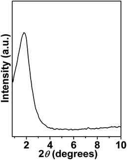 |
| | Fig. 1 Small angle powder XRD pattern of mesoporous NiFe2O4. | |
Nanostructure analysis
Field emission SEM (FE-SEM) images of NiFe2O4 are shown in Fig. 3a. From the SEM images, it is found that material is composed of very tiny nanoparticles with spherical morphology and uniform arrangement of nanoparticles. The representative HRTEM images of the material are shown in Fig. 3b–f. From the TEM analysis of NiFe2O4 it is clearly observable that; the material is composed self-assembled spherical nanoparticles of dimension ca. 5–9 nm to form interparticle mesoscopic voids space and mesoporosity (pores are surrounded by red circles in Fig. 3d). The high-resolution TEM image (Fig. 3e) of the NiFe2O4 material showed the presence of lattice fringes and suggested the high crystallinity of the material. The inter-planar distance is in quite good agreement with the d spacing of (400) crystal plane of face-cantered cubic structure with a unit cell parameter a = 8.36 Å. The selected area electron diffraction pattern of the material is shown in Fig. 3f. The diffraction spots are indexed corresponding to face-centered cubic (FCC) structure of single-phase nickel ferrite. d values corresponding to this FCC phase agrees very well with the powder X-ray diffraction pattern (Fig. 2). The histogram displaying particle size distribution as obtained from the TEM analysis is shown in Fig. S2.† The elemental mapping analysis for NiFe2O4 is shown in Fig. S3.† It suggested the presence of iron, nickel and oxygen, and their homogenous distribution throughout the mesoporous NiFe2O4 material.
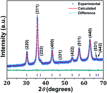 |
| | Fig. 2 Wide angle PXRD pattern of NiFe2O4. | |
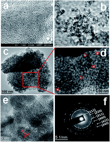 |
| | Fig. 3 FE-SEM image of the material NiFe2O4 (a), HR TEM image of NiFe2O4 showing self-assembled nanostructure and pore (b–d), high resolution TEM image of the material showing the lattice fringes (e) and (f) selected area electron diffraction (SAED) pattern of mesoporous NiFe2O4. | |
N2 adsorption–desorption study of nickel ferrite nanoparticles
The N2 adsorption–desorption isotherms of mesoporous nickel ferrite nanoparticle are shown in Fig. 4. The Brunauer–Emmett–Teller (BET) surface area, pore volume and average pore dimension of the nickel ferrite material are estimated from the adsorption/desorption isotherms at 77 K. The isotherm can be classified typical type IV, which is characteristic for the mesoporous material together with H3 type hysteresis loop.19 The material showed a strong capillary uptake in the relative pressure range (P/P0) from 0.54 to 0.95, suggesting the presence of wide range of mesoporosity in the material. The BET surface area of the material is 74 m2 g−1 with a pore volume of 0.0988 cc g−1. The corresponding pore size distribution estimated by employing the non-local density functional theory (NLDFT)20 model is shown in the inset of Fig. 4. The average pore size distribution showed peaks centred at 6.96 nm. Pore width obtained from N2 sorption analysis is quite close agreement with those seen from the electron microscopic images (Fig. 3d).
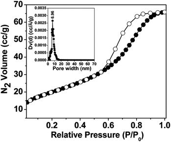 |
| | Fig. 4 N2 adsorption (●)-desorption (○)-adsorption isotherms of the material NiFe2O4 at 77 K. Corresponding NLDFT pore size distributions are shown in the inset. | |
Dc magnetization study
Thermal variation of zero-field cooled and field-cooled magnetization measured at 100 Oe is shown in Fig. 5. A broadened maximum is noticed around 220 K (Tmax) in the zero-field cooled curve. The field-cooled magnetization deviates from the zero-field cooled magnetization much above Tmax, indicating considerable interparticle interaction. Fig. 6 shows the isothermal magnetization curves at selective temperatures. The value of coercivity is 615 Oe at 20 K which nearly vanishes above Tmax. At 300 K, the sample shows almost zero coercivity as expected for superparamagnetic behaviour. All the magnetization curves below and above Tmax do not show a saturating trend upto 50 kOe. The value of magnetization at 50 kOe increases with decreasing temperature and approaches nearly 34 emu g−1 at 20 K. The value is much below the theoretical value (71.2 emu g−1). The considerably small value appears due to disordered surface spin.21 To characterize magnetic properties, the memory effect in both the zero-field cooled and field-cooled magnetization is investigated both in zero-field cooled and field-cooled protocols. The results for field-cooled protocol below Tmax are depicted in Fig. 7. In the study sample was cooled down from 300 K in a static magnetic field of 100 Oe at a constant rate of 1 K min−1 and magnetization is recorded as a function of temperature. During this cooling process sample temperature was arrested at three different temperatures, Thalt = 200, 150 and 100 K for 90 min each. At Thalt magnetic field was cut off for 90 min. After the completion of this ageing process, the measurements were resumed in field and the recorded curve is described as FC (waiting) curve as depicted in Fig. 7. The FC (waiting) curve consists of three sharp steps because of arrests at 200, 150 and 100 K. After reaching the base temperature at 20 K, the second cycle of measurement was carried out in the heating mode. Importantly, measurement in this cycle was carried out continuously at a rate of 1 K min−1 which is defined as FCH (memory) curve as depicted in the figure. Although FCH (memory) curve is recorded continuously, signature of steps at Thalt is evident in the FCH (memory) curve as displayed in Fig. 7. The results clearly demonstrate manifestation of previous memory during cooling cycle and display the memory effect. Memory effect in the field-cooled magnetization often ascribes to the extrinsic experimental artifact.22 To overcome it, memory effect was further measured in case of zero-field cooled magnetization as depicted by the difference of magnetization (ΔM) as a function of temperature in Fig. 8. The measurement is analogous to the protocol used for the field-cooled memory effect. During cooling process sample was cooled in zero field and halted at 100 and 150 K (below Tmax) for 180 min and then sample was further cooled to the base temperature at 40 K. In the heating cycle magnetization was measured in field continuously. An anomaly is still observed close to Thalt demonstrating memory effect, as evident by the anomalies in the ΔM plot with temperature in Fig. 8. The memory effect in zero-field cooling demonstrates consequence of the cooperative nature of spins with randomly frustrated interaction and is an intrinsic process which is typically observed in an atomic spin-glass system.23 Magnetization relaxation processes were recorded at three different temperatures at 100, 150 and 200 K. After cooling the sample in field-cooled conditions with a 100 Oe field, magnetization was recorded with time after switching off the field to zero. The M(t) at 200 K is fitted with the modified stretched exponential function M(t) = M0 − Mg[exp−(t/τ)β], where M0 and Mg are the ferromagnetic (FM) and exponential components of magnetization. β is an exponent which lies in the range 0 < β ≤ 1. τ is the relaxation time. Satisfactory fit using the above expression is displayed in Fig. 9 by the continuous curve. The values of Mg, M0, τ and β are 0.4802 emu g−1, −0.5395 emu g−1, 1138 s, and 0.51, respectively, at 200 K. In the above expression, β < 1 indicates activation against multiple anisotropy barriers and is consistent with the spin-glass-like behaviour.24 Existence of memory effect and relaxation dynamics fitted in the stretched exponential function with β < 1 suggest strong interparticle interactions and the interparticle interaction is tuned by the self assembly structure at the nanoscale. Magnetic behaviour below Tmax is quite different from the magnetic behaviour below the superparamagnetic blocking temperature as observed for the non-interacting fine nanoparticles. Here, we observe intrinsic memory effect below Tmax, pointing superspin-glass22 behaviour analogous to that observed for the atomic spin-glasses. The superspin-glass state further confirms strong interparticle interaction. Thus, Tmax represents superspin-glass transition temperature in place of superparamagnetic blocking temperature. Large difference between theoretically calculated saturation of magnetization and the current value at 20 K and 50 kOe probably occurs due to the disordered surface spin, which is significantly enhanced by the mesophase. These disordered surface spins give rise to the superspin-glass state at low temperature.25
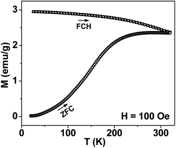 |
| | Fig. 5 Temperature variation of ZFC and FC magnetizations for mesoporous NiFe2O4 measured at 100 Oe. | |
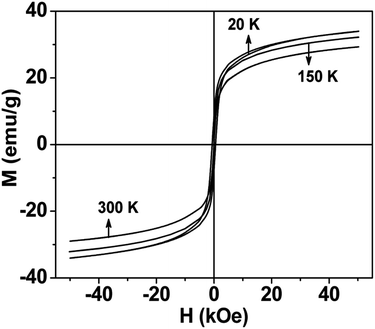 |
| | Fig. 6 Magnetic hysteresis loops of mesoporous NiFe2O4 at selected temperatures. | |
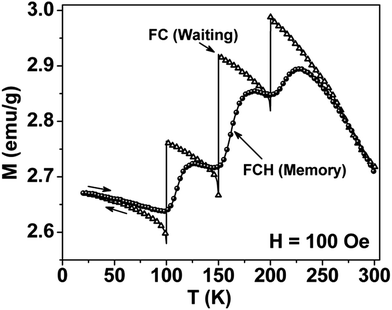 |
| | Fig. 7 Thermal variation of field-cooled (FC) magnetization in different modes for mesoporous NiFe2O4. The field was cutoff during temporary stops at 100, 150 and 200 K. Arrows display the measurements either in cooling or heating modes. Memory effect is demonstrated by the steps close to 100, 150 and 200 K in FCH (memory) curve. | |
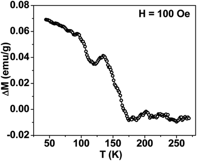 |
| | Fig. 8 Thermal variation of difference plot (ΔM) between ZFC (memory) and ZFC (reference), displaying absence of convincing signature of memory effect in mesoporous NiFe2O4. | |
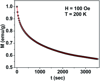 |
| | Fig. 9 Time (t) dependence of M at 200 K in zero field after cooling the sample in 100 Oe for mesoporous NiFe2O4. | |
Conclusions
We have synthesized crystalline mesoporous nickel ferrite nanomaterial with large surface area by using the supramolecular assembly of lauric acid as a structure directing agent under hydrothermal conditions. Negative charge of the lauric acid molecules under alkaline pH can interacts with the positively charged metal centres of nickel ferrite species via electrostatic interactions and thus to stabilize the mesophase. The dc magnetization results demonstrate evident manifestation of interparticle interaction. As a consequence of significant interparticle interaction memory effect is observed which is promising for technological applications in future.
Acknowledgements
VK and KD wishes to thank CSIR, New Delhi for Senior Research Fellowships. AB wishes to thank DST, New Delhi for instrumental supports through the DST Unit on Nanoscience and DST-SERB project grants.
References
-
(a) C. T. Black, C. B. Murray, R. L. Sandstrom and S. Sun, Science, 2000, 290, 1131 CrossRef CAS PubMed;
(b) D. Hong, Y. Yamada, T. Nagatomi, Y. Takai and S. Fukuzumi, J. Am. Chem. Soc., 2012, 134, 19572 CrossRef CAS PubMed;
(c) V. S. Coker, N. D. Telling, G. V. D. Laan, R. A. D. Pattrick, C. I. Pearce, E. Arenholz, F. Tuna, R. E. P. Winpenny and J. R. Lloyd, ACS Nano, 2009, 3, 1922 CrossRef CAS PubMed;
(d) J. F. Hochepied, P. Bonville and M. P. Pileni, J. Phys. Chem. B, 2000, 104, 905 CrossRef CAS;
(e) Z. Huang, Y. Zhu, J. Zhang and G. Yin, J. Phys. Chem. C, 2007, 111, 6821 CrossRef CAS;
(f) T. Hyeon, Y. Chung, J. Park, S. S. Lee, Y. W. Kim and B. H. Park, J. Phys. Chem. B, 2002, 106, 6831 CrossRef CAS;
(g) K. Winiarska, I. Szczygieł and R. Klimkiewicz, Ind. Eng. Chem. Res., 2013, 52, 353 CAS;
(h) R. D. Slaton, I. T. Bae, P. S. Lutz, L. Pathade and M. M. Maye, J. Mater. Chem. C, 2015, 3, 6367 RSC;
(i) R. T. Olsson, G. S. Alvarez, M. S. Hedenqvist, U. W. Gedde, F. Lindberg and S. J. Savage, Chem. Mater., 2005, 17, 5109 CrossRef CAS;
(j) Y. Min, M. Akbulut, K. Kristiansen, Y. Golan and J. Israelachvili, Nat. Mater., 2008, 7, 527 CrossRef CAS PubMed;
(k) S. Dey, R. Gomes, R. Mondal, S. K. Dey, P. Dasgupta, A. Poddar, V. R. Reddy, A. Bhaumik and S. Kumar, RSC Adv., 2015, 5, 78508 RSC.
-
(a) A. H. Lu, E. L. Salabas and F. Schuth, Angew. Chem., Int. Ed., 2007, 46, 1222 CrossRef CAS PubMed;
(b) K. A. Pettigrew, J. W. Long, E. E. Carpenter, C. C. Baker, J. C. Lytle, C. N. Chervin, M. S. Logan, R. M. Stroud and D. R. Rolison, ACS Nano, 2008, 2, 784 CrossRef CAS PubMed;
(c) D. Hong, Y. Yamada, M. Sheehan, S. Shikano, C. H. Kuo, M. Tian, C. K. Tsung and S. Fukuzumi, ACS Sustainable Chem. Eng., 2014, 2, 2588 CrossRef CAS;
(d) F. Hong, C. Yan, Y. Si, J. He, J. Yu and B. Ding, ACS Appl. Mater. Interfaces, 2015, 7, 20200 CrossRef CAS PubMed;
(e) E. H. Walker Jr, M. L. Breen and A. W. Apblett, Chem. Mater., 1998, 10, 1265 CrossRef;
(f) Y. Konishi, T. Kawamura and S. Asai, Ind. Eng. Chem. Res., 1996, 35, 320 CrossRef CAS;
(g) J. Singh, A. Roychoudhury, M. Srivastava, V. Chaudhary, R. Prasanna, D. W. Lee, S. H. Lee and B. D. Malhotra, J. Phys. Chem. C, 2013, 117, 8491 CrossRef CAS.
- X. Gu, W. Zhu, C. Jia, R. Zhao, W. Schmidt and Y. Wang, Chem. Commun., 2011, 47, 5337 RSC.
-
(a) A. M. Kulkarni, U. V. Desai, K. S. Pandit, M. A. Kulkarni and P. P. Wadgaonkar, RSC Adv., 2014, 4, 36702 RSC;
(b) Y. Cheng, Y. Zheng, Y. Wang, F. Bao and Y. Qin, J. Solid State Chem., 2005, 178, 2394 CrossRef CAS;
(c) J. Huo and M. Wei, Mater. Lett., 2009, 63, 1183 CrossRef CAS;
(d) A. R. O. Rodrigues, I. T. Gomes, B. G. Almeida, J. P. Araujo, E. M. S. Castanheira and P. J. G. Coutinho, Phys. Chem. Chem. Phys., 2015, 17, 18011 RSC.
-
(a) S. Banerjee, A. Datta, A. Bhaumik and D. Chakravorty, J. Appl. Phys., 2011, 110, 064316 CrossRef;
(b) A. Perejon, P. E. Sanchez-Jimenez, L. A. Perez-Maqueda, J. M. Criado, J. R. de Paz, R. Saez-Puche, N. Maso and A. R. West, J. Mater. Chem. C, 2014, 2, 8398 RSC.
-
(a) D. H. Chen and X. R. He, Mater. Res. Bull., 2001, 36, 1369 CrossRef CAS;
(b) M. George, A. M. John, S. S. Nair, P. A. Joy and M. R. Anantharaman, J. Magn. Magn. Mater., 2006, 302, 190 CrossRef CAS;
(c) P. X. Li, R. G. Ma, Y. Zhou, Y. F. Chen, Z. Z. Zhou, G. H. Liu, Q. Liu, G. H. Peng and J. C. Wang, RSC Adv., 2015, 5, 44476 RSC.
- C. Nordhei, K. Mathisen, I. Bezverkhyy and D. Nicholson, J. Phys. Chem. C, 2008, 112, 6531 CAS.
-
(a) S. Prasad and N. S. Gajbhiye, J. Alloys Compd., 1998, 265, 87 CrossRef CAS;
(b) S. Prasad and N. S. Gajbhiye, J. Alloys Compd., 1998, 265, 87 CrossRef CAS.
-
(a) C. B. Berthelin, D. Chaumont and D. Stuerga, J. Solid State Chem., 2008, 181, 616 CrossRef;
(b) M. Sertkol, Y. Köseoglu, A. Baykal, H. Kavas, A. Bozkurt and M. S. Toprak, J. Alloys Compd., 2009, 486, 325 CrossRef CAS.
-
(a) P. Sivakumar, R. Ramesh, A. Ramanand, S. Ponnusamy and C. Muthamizhchelvan, Mater. Res. Bull., 2011, 46, 2204 CrossRef CAS;
(b) P. R. Kumar and S. Mitra, RSC Adv., 2013, 3, 25058 RSC;
(c) K. O. Abdulwahab, M. A. Malik, P. O'Brien, G. A. Timco, F. Tuna, R. E. P. Winpenny, R. A. D. Pattrick, V. S. Coker and E. Arenholz, J. Mater. Chem. C, 2014, 2, 6781 RSC.
-
(a) J. lfiiguez and C. Pereira, Appl. Phys. A, 1985, 36, 159 CrossRef;
(b) M. Thakur, S. Majumdar, S. Giri, A. Bhaumik, M. Nandi, H. Nakamura, H. Kobayashi and T. Kohara, J. Phys.: Condens. Matter, 2008, 20, 1 Search PubMed.
-
(a) S. C. Warren, L. C. Messina, L. S. Slaughter, M. Kamperman, Q. Zhou, S. M. Gruner, F. J. DiSalvo and U. Wiesner, Science, 2008, 320, 1748 CrossRef CAS PubMed;
(b) Y. Lu, Angew. Chem., Int. Ed., 2006, 45, 7664 CrossRef CAS PubMed;
(c) V. Kumari, M. Sasidharan and A. Bhaumik, Dalton Trans., 2015, 44, 1924 RSC;
(d) D. Chandra, S. Mridha, D. Basak and A. Bhaumik, Chem. Commun., 2009, 2384 RSC.
- S. Banerjee, P. Hajra, M. R. Mada, A. Bhaumik, S. Bandyopadhyay and D. Chakravorty, J. Magn. Magn. Mater., 2013, 332, 98 CrossRef CAS.
-
(a) A. Kale, S. Gubbala and R. D. K. Misra, J. Magn. Magn. Mater., 2004, 277, 350 CrossRef CAS;
(b) A. Baykal, N. Kasapoglu, Y. Koseoglu, M. S. Toprak and H. Bayrakdar, J. Alloys Compd., 2008, 464, 514 CrossRef CAS;
(c) J. Haetge, C. Suchomski and T. Brezesinski, Inorg. Chem., 2010, 49, 11619 CrossRef CAS PubMed.
-
(a) A. K. Patra, S. K. Das and A. Bhaumik, J. Mater. Chem., 2011, 21, 3925 RSC;
(b) A. K. Patra, A. Dutta and A. Bhaumik, J. Hazard. Mater., 2012, 201, 170 CrossRef PubMed.
- V. Kumari and A. Bhaumik, Dalton Trans., 2015, 44, 11843 RSC.
-
(a) V. Masheva, M. Grigorova, N. Valkov, H. J. Blythe, T. Midlarz, V. Blaskov, J. Geshev and M. Mikhov, J. Magn. Magn. Mater., 1999, 196–197, 128 CrossRef CAS;
(b) K. Gandha, K. Elkins, N. Poudyal and J. P. Liu, J. Appl. Phys., 2015, 117, 17A736 CrossRef;
(c) S. R. Ahmed, S. B. Ogale, G. C. Papaefthymiou, R. Ramesh and P. Kofinas, Appl. Phys. Lett., 2002, 80, 1616 CrossRef CAS;
(d) S. Ammar, A. Helfen, N. Jouini, F. Fiévet, I. Rosenman, F. Villain, P. Molinié and M. Danot, J. Mater. Chem., 2001, 11, 186 RSC.
- M. Pramanik, A. K. Patra and A. Bhaumik, Dalton Trans., 2013, 42, 5140 RSC.
-
(a) D. Zhao, D. Yuan, D. Sun and H. C. Zhou, J. Am. Chem. Soc., 2009, 131, 9186 CrossRef CAS PubMed;
(b) M. Kruk and M. Jaroniec, Chem. Mater., 2001, 13, 3169 CrossRef CAS;
(c) M. Pramanik and A. Bhaumik, Chem.–Eur. J., 2013, 19, 8507 CrossRef CAS PubMed.
- P. I. Ravikovitch and A. V. Neimark, J. Phys. Chem. B, 2001, 105, 6817 CrossRef CAS.
- S. K. Sabyasachi, M. Patra, S. Majumdar, S. Giri, S. Das, V. S. Amaral, O. Iglesias, W. Borghols and T. Chatterji, Phys. Rev. B, 2012, 86, 104416 CrossRef.
-
(a) M. Sasaki, P. E. Jonsson, H. Takayama and P. Nordblad, Phys. Rev. Lett., 2004, 93, 139701 CrossRef CAS PubMed;
(b) R. K. Zheng, H. Gu and X. X. Zhang, Phys. Rev. Lett., 2004, 93, 139702 CrossRef CAS PubMed;
(c) D. De, A. Karmakar, M. K. Bhunia, A. Bhaumik, S. Majumdar and S. Giri, J. Appl. Phys., 2012, 111, 033919 CrossRef;
(d) D. De, K. Dey, S. Majumdar and S. Giri, Solid State Commun., 2012, 152, 1857 CrossRef CAS;
(e) D. De, S. Majumdar and S. Giri, J. Magn. Magn. Mater., 2015, 394, 448 CrossRef CAS.
-
(a) J. A. Mydosh, Spin Glasses: An Experimental Introduction, Taylor and Francis, London, 1993 Search PubMed;
(b) O. Cador, F. Grasset, H. Haneda and J. Etourneau, J. Magn. Magn. Mater., 2004, 268, 232 CrossRef CAS;
(c) M. Ósth, D. Hérisson, P. Nordblad, J. A. D. Toro and J. M. Riveiro, J. Magn. Magn. Mater., 2007, 313, 373 CrossRef.
-
(a) A. Bhattacharyya, S. Giri and S. Majumdar, Phys. Rev. B, 2011, 83, 134427 CrossRef;
(b) K. De, M. Patra, S. Majumdar and S. Giri, J. Phys. D: Appl. Phys., 2007, 40, 7614 CrossRef CAS;
(c) K. Dey, S. Majumdar and S. Giri, Phys. Rev. B, 2014, 90, 184424 CrossRef.
- R. H. Kodama, A. E. Berkowitz, E. J. McNiff Jr and S. Foner, Phys. Rev. Lett., 1996, 77, 394 CrossRef CAS PubMed.
Footnote |
| † Electronic supplementary information (ESI) available. See DOI: 10.1039/c6ra05483h |
|
| This journal is © The Royal Society of Chemistry 2016 |
Click here to see how this site uses Cookies. View our privacy policy here. ![[3 with combining macron]](https://www.rsc.org/images/entities/char_0033_0304.gif) m space group with lattice parameter a = 8.364 Å. Rietveld refined structural parameters are given in ESI in Table S1.†
m space group with lattice parameter a = 8.364 Å. Rietveld refined structural parameters are given in ESI in Table S1.†


