
Dimensional tailoring of nitrogen-doped graphene for high performance supercapacitors†
Seung Yong Leea,
Chang Hyuck Choib,
Min Wook Chunga,
Jae Hoon Chungb and
Seong Ihl Woo*ab
aGraduate School of EEWS, Korea Advanced Institute of Science and Technology, Daejeon 305-701, Republic of Korea. E-mail: siwoo@kaist.ac.kr
bDepartment of Chemical and Biomolecular Engineering, Korea Advanced Institute of Science and Technology, Daejeon 305-701, Republic of Korea
First published on 6th June 2016
Abstract
Due to its unique properties, graphene has been regarded as a promising electrode material in various fields of energy conversion and storage devices. In supercapacitors, however, the graphene electrodes show unexpectedly poor energy densities due to low transferability of charge carriers in the randomly overlaid graphene electrodes. For efficient charge transfers, construction of three-dimensional graphene structures has been generally considered. In this study, contrary to previous strategies, the graphene structures are sequentially tailored from two-dimensional sheets to one-dimensional ribbons and zero-dimensional dots, and then their capacitive behaviors are investigated in a symmetric unit cell. Dimensionality of the graphene determines the local pore structure and morphology of the fabricated graphene electrodes. Hence, it strongly affects the transfer rate of charge carriers and capacitive performance. One-dimensional ribbons, which have a high length-to-width ratio and a consequent net-like porous structure in the fabricated electrode, demonstrate an efficient charge transferability with 378 F g−1 specific capacitance at 1 A g−1 current density in 6 M KOH electrolyte. Additionally, a durability study coupled with X-ray photoelectron spectroscopy (XPS) reveals that performance degradation of the graphene-based electrodes mainly results from surface oxidation which inhibits facile electron transfers.
Introduction
In parallel with the increasing demands for the development of energy harvesting and conversion technologies, storage systems have been regarded as being more important for a stable energy supply. Among the diverse energy storage devices, supercapacitors have attracted a lot of attention due to their high power densities and reversibility with various applicable areas including portable electronics and hybrid vehicles.1–3 According to their working principles, supercapacitors can be classified as electric double layer capacitors (EDLC) based on electrostatic charge accumulation at the interfaces of the electrode and the electrolyte4–8 and pseudocapacitors based on fast and reversible Faradic reactions.3 In the EDLC, carbon materials (e.g. nanotubes, aerosol, hydrogel and etc.), having large surface area and good electric conductivity with high chemical stability, have been generally used for high performance capacitors.9–14Among the various carbon materials, due to its superior electrical and mechanical properties originated from the two-dimensional layered structure of sp2-hybridized carbon, graphene has been extensively applied in many energy conversion and storage technologies. In EDLC, however, pristine graphene shows poor capacitive ability (135 F g−1).7 Doping of other heteroatoms (e.g. N, B, P, S and etc.) was an alternate approach to improve its performance by providing efficient adsorption/desorption sites for charge carriers on the graphene surface.15–19 However, their performance was still lower than the theoretical value of the graphene (550 F g−1)9 and even those of similarly modified other carbon-based materials.6,20,21
This unexpected low performance is primarily ascribed to the low transferability of charge carriers such as electrons and ions in the fabricated electrode. Brownson et al. suggested by their theoretical and experimental studies that large basal plane of the graphene impedes efficient electron transfer on the fabricated electrode, and argued that graphene is not a suitable candidate for electrochemistry.22 Electron transfer on the graphene is strongly directional dependent (in-plane) with extremely low out-of-plane conductivities. Moreover, when the graphene is used as an electrode, the large sheet-like layers could be randomly piled up each other (face-to-face), which induce blockage of the pore spaces where the charge carriers are transferred (Fig. 1a). Therefore, increasing its dimensionality (D) from 2D- to 3D-structures with high porosities (e.g. 3D-graphene, pillared graphene and etc.) have been suggested as a promising strategy for modifications on graphene electrodes.10,11,23–28
 | ||
| Fig. 1 Schematic illustrations of (a) blockage of the pore spaces on graphene electrode and (b) net-like porous structure of the fabricated rRb electrode. | ||
Herein, contrary to previous approaches, we adopted an inverse concept to improve capacitive properties of the graphene derivatives, the decrement in dimensionality. Dimensionality of the graphene was sequentially reduced from the sheets (2D) to the ribbons (1D), and further to the dots (0D), and then their physical and capacitive characteristics were extensively investigated. This study showed that dimensionality of the graphene derivatives determined the morphology of the fabricated electrode, which affected the transfer rates of charge carriers and consequently capacitive performance. In a symmetric supercapacitor cell with 6 M KOH electrolyte, the optimized graphene electrode, 1D graphene ribbons with high length-to-width ratios having net-like porous structures, demonstrated superior capacitance of 378 F g−1 at current density of 1 A g−1. Furthermore, we suggested an insight about the origin of the performance degradation on the graphene derivatives via long-cycle operations (over 10![[thin space (1/6-em)]](https://www.rsc.org/images/entities/char_2009.gif) 000 cycles) coupled with X-ray photoelectron spectroscopy (XPS) analysis.
000 cycles) coupled with X-ray photoelectron spectroscopy (XPS) analysis.
Experimental
Preparation of the graphene derivatives
Multi-walled carbon nanotubes (MWCNT, 3 g, Carbon Nano-material Technology Co., LTD, Republic of Korea) were dispersed in the mixture of 360 mL of H2SO4 (95.0%, Samchun chemicals, Republic of Korea) and 40 mL of H3PO4 (85.0%, Samchun chemicals, Republic of Korea), and then 18 g of KMnO4 (99.0%, Sigma-Aldrich, USA) was added slowly. The solution was heated to 50 °C and stirred for 12 h. After cooled to the room temperature, the solution was poured onto the ice bath with 5 mL of H2O2 (35.0%, Samchun chemicals, Republic of Korea), followed by centrifugation at 6000 rpm for 30 min. Obtained samples were sonicated for 10 min in 200 mL of HCl solution (35.0%, Samchun chemicals, Republic of Korea) to remove residual metallic phases and centrifuged again. After several washing with deionized (DI) water, the ribbon-like graphene oxides (oxRb) was obtained. Sequentially, the dot-like graphene oxides (oxDot) was prepared by ball milling of the oxRb with zirconia balls for 24 h at 500 rpm rotating speed. In the similar method, the sheet-like graphene oxides (oxSh) was synthesized by chemical oxidation of graphite. The reduced ribbon (rRb), reduced dot (rDot) and reduced sheet (rSh) were synthesized via hydrazine reduction of oxRb, oxDot and oxSh, respectively. The oxidized samples were stirred in the solution composed with 300 mL of DI water and 50 mL of hydrazine (35 wt%, Sigma-Aldrich, USA) at 95 °C for 24 h, and then gathered by centrifugation after several washing with deionized water.Physical characterization
The physical characterizations were performed with transmission electron microscopy (TEM), scanning electron microscopy (SEM), X-ray diffraction (XRD), XPS, Raman spectroscopy, elemental analysis (EA) and Brunauer–Emmett–Teller (BET) analysis. The TEM images were taken with a JEM2100-F (Jeol Ltd.) operated at 200 kV. The SEM images were obtained using a HD-2300A (Hitachi) operated at 5.0 kV. The XRD patterns were obtained from a D.MAX-2500 (Rigaku) operated at 40 kV and 300 mA with Cu-Kα as a radiation source. The XPS data was obtained by using a Sigma Probe (Thermo VG Scientific). Raman spectroscopy was performed using LabRAM HR UV/Vis/NIR (Horiba Jobin Yvon) with a laser source of 514 nm. The EA was acquired from a FlashEA 1112. The BET surface area data was obtained from a Micrometrics ASAP 2010 apparatus at 77 K.Fabrication of supercapacitors
Ink solutions for supercapacitor electrodes were prepared by mixing active materials, polyvinylidene fluoride (PVDF, Sigma-Aldrich, USA) as a binder, and Ketjen black EC-300J as an additive material (85:10:5 wt%) in 1 mL of isopropanol (99.5%, Samchun chemicals, Republic of Korea). The ink solution was well dispersed and coated onto 1 cm2 carbon paper until the loading of active materials being 1 mg. After dried in vacuum oven, homemade supercapacitor cells were assembled using the same two electrodes which were separated by a glassy filter paper soaked with 6 M KOH (95.0%, Samchun chemicals, Republic of Korea).
Electrochemical measurements
Capacitive performances of the supercapacitor cells were measured by cyclic voltammetry (CV), galvanostatic charge–discharge, and electrochemical impedance spectroscopy (EIS) (CHI 760d, CH Instruments Inc.). The potential range of CV and galvanostatic charge–discharge measurements were taken from 0 to 1.0 V. EIS measurements of the prepared materials were examined with the frequency range from 0.1 to 10000 Hz at 5 mV of amplitude. Stabilities of the cells were tested by 1000 and 10000 cycles of galvanostatic charge–discharge at 1 and 5 A g−1 of current density, respectively. The specific capacitances from the galvanostatic charge–discharge curves (Csp,gcd) were calculated by using an equation:| Csp,gcd = 4 × (I × Δt)/(m × ΔV) | (1) |
 | (2) |
Results and discussion
To prepare various graphene derivatives having different dimensionalities, pristine graphite and carbon nanotubes (diameter = ∼20 nm) were firstly oxidized with KMnO4 for synthesizing oxSh and oxRb, respectively. Consecutively, the oxDot was obtained through a physical fragmentation of oxRb using ball-milling for 24 h. Regardless of the graphene dimensionality, XRD patterns of the samples showed a peak at about 10°, which indicated successful oxidations of the pristine carbon sources (Fig. S1a†).29,30 XPS measurements also exhibited an intensive peak from C–O bonding at 286.5 eV (Fig. S1b†), inferring the highly oxidized carbon products. Similar XRD and XPS patterns between oxRb and oxDot indicated the oxygen functionality were not considerably changed during the ball-milling process. As shown in TEM (Fig. 2), the oxSh had a large planar morphology with several μm of lateral length, but the oxRb showed a long ribbon-like morphology. Width of the oxRb from the TEM images was approximately 60 nm, which was well corresponded to a width mathematically calculated from a diameter of the pristine carbon nanotubes (2πr = ∼62.8 nm, r = 10 nm), indicating successful unzipping of the pristine carbon nanotubes. After mechanical ball-milling of the oxRb, the oxDot exhibited relatively small planar fragments, of which size were randomly distributed within tens of nm. The high-magnification TEM images of the oxSh displayed sheet-like structure with wrinkled layers. The prepared oxRb showed layered structures, indicating that the pristine CNTs were unzipped through the chemical oxidation, resulting in the formation of ribbon-like graphene oxide. After physical fragmentation of the oxRb, the oxDot exhibited smaller planar fragment of dot-like graphene oxide with several graphene layers. The oxRb and oxDot were consisted of 5 ∼ 7 layers, indicating they were unzipped from a chemical oxidation of multi-walled CNTs (10 ∼ 15 layers) (Fig. S2†). | ||
| Fig. 2 TEM images of the prepared graphene oxides: (a) oxSh, (b) oxRb and (c) oxDot. | ||
For applications in supercapacitors, oxygen-enriched surfaces of oxSh, oxRb and oxDot were then chemically modified with hydrazine, producing rSh, rRb and rDot, respectively. As shown in SEM (Fig. S3†), the graphene derivatives revealed similar morphologies with TEM images. The rSh showed large planar structure, while the rRb revealed net-like structure with a large length-to-width ratio. The rDot, which were derived via the ball-milling process from ribbon-like graphene, displayed morphology of more wrinkled and smaller fragments. Oxygen functional groups on the oxidized graphene materials were almost eliminated through the hydrazine reduction. In the XRD patterns (Fig. 3a), the peak at about 10° greatly decreased after the reduction, while an alternate peak at 26° (refers to the graphitic carbon) was newly emerged. Furthermore, the C–O bonding peak at 286.5 eV in XPS results was also diminished after the hydrazine treatment (Fig. 3b). Additional Raman spectroscopy analysis also exhibited similar responses and ID/IG values within the prepared samples (Fig. S4†). Simultaneously, the nitrogen atoms were doped in the graphene samples. The effects of N-species in the field of supercapacitors has been investigated as well as in other energy storage and conversion systems. U. B. Nasini et al. reported presence of N groups could improve the electric double layer capacitance due to the enhancement of the adsorption/desorption ability of ions.31 Other group reported N groups contributed to enhancement of capacitance of supercapacitors in the aqueous electrolyte through polarized sites where the reversible gaining/losing of electrons and adsorption/desorption of protons take place.32 These implied that nitrogen species could enhance by higher amounts of amine/amide and pyridinic-oxide which improved electron transfer and adsorption/desorption with their polarized sites. The XPS-N1s results indicated that amine/amide, pyridinic-N, graphitic-/pyrrolic-N and pyridinic oxide were present. Among them, amine/amide and pyridinic-N were the dominant species of the doped nitrogen on the prepared graphene materials (Fig. 3c). The compositions from the EA of the graphene derivatives (Table S1†) were examined similar nitrogen contents of 5.9 (±0.4) at% in all samples. Hence, it could be concluded that characteristics of the rRb, rDot, and rSh were almost the same in terms of composition, crystal structure, defect site and type of nitrogen-doped.
 | ||
| Fig. 3 Physical characterizations of the chemically reduced graphene materials. (a) XRD patterns. The intense peaks at 26° in the XRD result (indicated by arrows) refer to graphitic carbon. (b) XPS-C1s and (c) -N1s results. The C–C bonding peaks were assigned in XPS-C1s and XPS-N1s signals were deconvoluted into pyridinic-N, amine/amide, graphitic-/pyrrolic-N and pyridinic oxide. | ||
Capacitive behaviors of the prepared graphene materials were studied in a homemade symmetric cell using 6 M KOH electrolyte. Galvanostatic charge–discharge responses of the graphene derivatives were examined in the potential window of 1.0 V (from 0 to 1.0 V) with 1 A g−1 current density (Fig. 4a). The fabricated rSh electrode marked 157 F g−1 capacitance, of which performance was similar with those of the previously reported reduced graphene.6,20,21,33 After the dimensionality tailoring, however, the capacitive performances were dramatically changed. The fabricated rRb and rDot demonstrated 378 and 267 F g−1 capacitances at 1 A g−1 of current density, respectively. The performance enhancement was also confirmed at different current densities in galvanostatic charge–discharge methods (Fig. 4b and S5†) and different scan rates in CV methods (Fig. S6†). It is noteworthy that the excellent specific capacitance of the rRb (378 F g−1 at 1 A g−1) exceeds previously reported graphene derivatives with the two electrode system (Table S2†).
 | ||
| Fig. 4 Capacitive performances of the fabricated supercapacitors. (a) Galvanostatic charge–discharge curves at 1 A g−1 in 6 M KOH electrolyte using a symmetric cell. (b) Specific capacitance in galvanostatic charge–discharge methods as a function of current density. | ||
Generally, capacitive performances of carbon-based materials are determined by surface-functionalities, pore sizes, surface areas, and electron/mass transfer rates.4,6,8,20,34 Aforesaid, however, the prepared graphene materials had similar XRD patterns (Fig. 3a), Raman spectra (Fig. S4†), pore sizes (∼3 nm; Fig. S7b†) and nitrogen-doping/functional group distributions (pyridinic-N and amine/amide rich functionalities with 5.9 ± 0.4 at% of nitrogen-contents; Fig. 3c and Table S1†). The noticeable differences in the prepared graphene samples were their dimensionalities and surface areas. The N2-adsorption isotherm results revealed 102.6, 423.2, and 290.5 m2 g−1 of BET surface areas with a H3-type of hysteresis loop (IUPAC classification) for rSh, rRb, and rDot, respectively (Fig. S7a†). Considering the surface area-normalized capacitance, rRb revealed the lowest value (0.89 F m−2) compared to those of rSh (1.53 F m−2) and rDot (0.92 F m−2). The results elucidated that the improved capacitive performance in the rRb was primarily ascribed to the increased accessible surface area in the fabricated graphene electrodes regarding to its dimensionality.
To obtain further insights in the superior capacitive performance on the rRb, the kinetic behaviors of electrons and mass carriers in the prepared electrodes were analyzed through EIS study (Fig. 5). As confirmed by the Nyquist plot (Fig. 5a), supercapacitors fabricated with the prepared graphene materials exhibited the similar equivalent series resistances (ESR) which refer to the combined values of the materials–current collector contact resistance, the bulk solution resistance, and the intrinsic resistance of the electrode material: 1.1, 0.9, and 1.0 Ω for the rSh, rRb, and rDot, respectively. Otherwise, charge transfer resistances, which are arisen by the charge carriers at the interfaces between electrode surfaces and electrolyte, showed considerable difference that the rRb electrode has the lowest value (8.5 Ω) rather than those of rSh (21.2 Ω) and rDot (20.6 Ω). This revealed that reduced charge transfer resistance of rRb among the graphene derivatives. More importantly, dimensionality of the graphene samples was strongly correlated with transferability of mass carriers. In the Bode plot (Fig. 5b), the resistance at the low frequency region, representing a resistance from mass transfers, was 69.0 Ω for the rSh. After the dimensional modification, however, the resistance was decreased to 35.4 Ω and 53.5 Ω for the rRb and rDot, respectively, indicating facile mass transport in the fabricated electrode. The specific capacitances of the graphene samples were correlated with their resistances at low frequency region from the Bode plot (Fig. 5c). Fig. 5c showed that the specific capacitances were inversely proportional to the mass transfer resistances. Considering the low deviations in ESR values (10%, 1.0 ± 0.1 Ω), but the dramatic changes in capacitances, it can be concluded that the high capacitive performance of rRb was mainly resulted from enhanced mass transferability in the fabricated electrode.
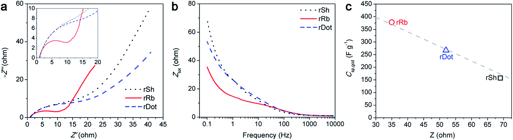 | ||
| Fig. 5 EIS investigations on the fabricated supercapacitors. (a) Nyquist and (b) Bode plots obtained with a 5 mV amplitude and a frequency range from 0.1 to 10000 Hz. Magnified Nyquist plot at high frequency region were inserted in (a). (c) The correlations between specific capacitances of the graphene derivatives at 1 A g−1 and their mass transfer resistances at low frequency region obtained from the Bode plot. | ||
SEM analysis on the fabricated rRb electrode revealed a net-like morphology with an interconnected pore structure (Fig. 6b). This unique morphology was attained from a large length-to-width ratio of rRb, which can be woven together (Fig. 1b). Therefore, the mass carriers can efficiently penetrate into the most part of the graphene surface through the net-holes. However, the rSh and rDot, which had the length-to-width ratio of nearly 1, were readily piled up face-to-face on the randomly fabricated electrode, consequently blocking constructions of pore frameworks and then impeding efficient mass transfers with the increment of diffusion distances (Fig. 1a). These stacking effects were reasonably intensified as the lateral length of the graphene increases, and the limited portions (especially only upper surface) of the fabricated graphene electrode can be contacted with the electrolyte.
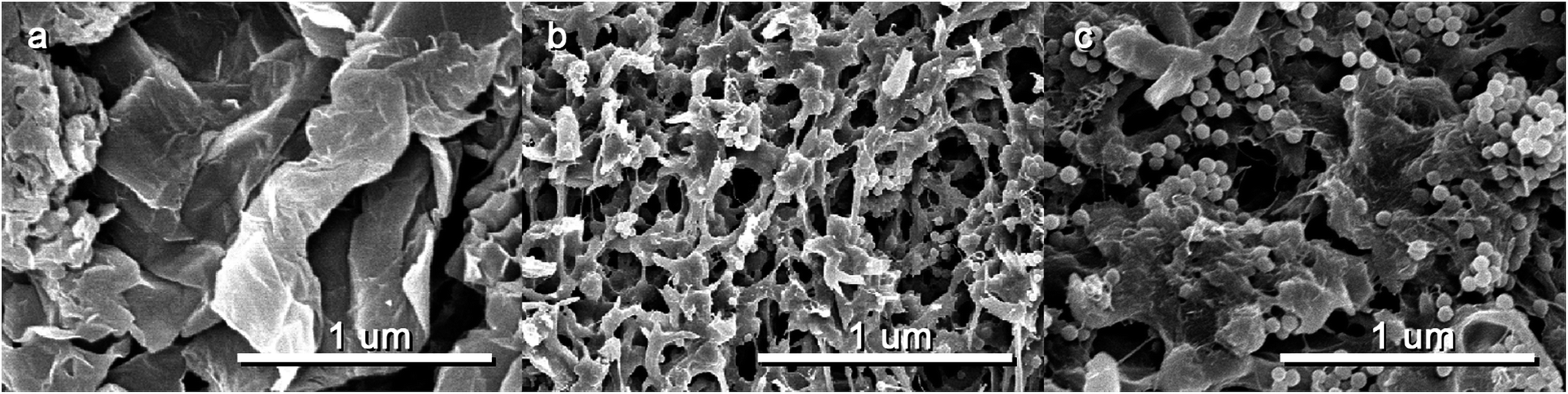 | ||
| Fig. 6 Morphology of the fabricated graphene electrodes. SEM images of (a) rSh, (b) rRb and (c) rDot electrodes obtained at a 5 kV electron acceleration voltage. The small granules in the SEM images indicates PVDF particles, which were used as a binder. | ||
Stability of the supercapacitors was tested by 1000 cycles of operations with 1 A g−1 of current density. After the cyclic operations, the supercapacitors fabricated using rSh, rRb and rDot revealed −2.5, −2.2 and −2.3 %p of performance drop, respectively (Fig. 7a). These degradation rates were similar with those of the previous carbon-based supercapacitors.13,24,25,35,36 Meanwhile, the study to investigate the origin of the performance decay has yet not been established well probably due to the relatively higher stability of carbon-based materials than that of pseudo-capacitive materials such as metal oxides and conducting polymers.
 | ||
| Fig. 7 Stability of the fabricated supercapacitors. (a) Relative capacitance changes during 1000 cycles of operations at 1 A g−1 current density. (b) Relative capacitance change for the rRb-fabricated supercapacitors during 10000 cycles of operations at 5 A g−1 current density. After 10000 cycles of the operations, (c) XPS-O1s responses and (d) Nyquist plots for the rRb-fabricated supercapacitors were investigated. | ||
To understand the underlying degradation mechanisms of the carbon-based electrodes, the supercapacitors were degraded under much harsh operating conditions, the 10000 cycles at 5 A g−1 current density in 6 M KOH electrolyte (Fig. 7b), and then the XPS analysis was consecutively conducted to figure out changes in local chemical structure on the fabricated graphene electrode after the degradation. After the 10000 cycles of the operation, −22.1 %p of performance decreased compared with the pristine rRb electrode. It can be presumed that deformations in the nitrogen functionalities on the graphene samples introduces the considerable performance loss, while the XPS-N1s measurements disclosed that the nitrogen functionalities did not significantly change after the degradations; slight increment in pyridinic-oxide and decrement in other functionalities were observed but the differences were trivial (Fig. S8†). However, oxygen contents on the fabricated electrodes were dramatically increased after the degradation (Fig. 7c). The O/C atomic ratio as confirmed by XPS-O1s was 0.14 for the pristine rRb, which increased to 0.50 after the 10000 cycles of operations. The results indicated that the degradation in capacitive performance is highly related with oxidation of the graphene electrodes. It has been suggested that the oxygen-functional groups prefer being present at the graphite (or graphene) microcrystallites, and consequently inhibit an efficient electron transfer from one microcrystallite to the next.37 However, as shown in SEM images (Fig. S9†) after cycling operations, noticeable structural differences of the fabricated graphene electrodes were not observed. An EIS study demonstrated decline in electron transfer rates after the cyclic operations; the ESR of rRb considerably increased over 19.6 times (17.4 Ω) after degradation tests (Fig. 7d). Therefore, it can be concluded that the capacitive performance loss is mainly resulted from surface oxidation and consequent inhibition of efficient electron transfers.
Conclusions
In conclusions, the dimensionality of the nitrogen-doped graphene was sequentially modified from 2D sheets to 1D ribbons and then 0D dots for applications in supercapacitors. The rSh having a sheet-like morphology (2D) showed 157 F g−1 of specific capacitance at 1 A g−1 current density in 6 M KOH electrolyte, but the dimensional modifications improved their performance significantly. Especially, an excellent capacitance of 378 F g−1 was obtained from the rRb. We demonstrated that a key factor, which determined initial capacitive performance, was the mass transferability in the fabricated graphene electrodes. High length-to-width ratios of the graphene were highly desirable to prohibit the blocking of internal pore structures and to produce net-like pore connections to maximize the utilizations of the graphene electrodes. Otherwise, the capacitive performance degradation was introduced from increment in electrical resistance on the fabricated electrodes without considerable distortion in nitrogen functionalities. The surface of the graphene electrodes were oxidized during the operations and oxygen functional groups were newly generated on the graphene electrodes, which induced a barrier of an electron transfer in the fabricated electrodes. The preparation strategy of the tailoring graphene dimensionality and the understanding in performance decade would open up different visions for developing new carbon-based supercapacitors with high performance and stability.Acknowledgements
This research is supported by BK21PLUS program through the National Research Foundation (NRF).Notes and references
- M. Meyyappan, J. Vac. Sci. Technol., A, 2013, 31, 050803 Search PubMed.
- C. J. Shearer, A. Cherevan and D. Eder, Adv. Mater., 2014, 26, 2295–2318 CrossRef CAS PubMed.
- P. Simon and Y. Gogotsi, Nat. Mater., 2008, 7, 845–854 CrossRef CAS PubMed.
- F. Béguin, V. Presser, A. Balducci and E. Frackowiak, Adv. Mater., 2014, 26, 2219–2251 CrossRef PubMed.
- X. Li and B. Wei, Nano Energy, 2013, 2, 159–173 CrossRef CAS.
- M. Pumera, Energy Environ. Sci., 2011, 4, 668–674 CAS.
- M. D. Stoller, S. Park, Y. Zhu, J. An and R. S. Ruoff, Nano Lett., 2008, 8, 3498–3502 CrossRef CAS PubMed.
- L. L. Zhang and X. S. Zhao, Chem. Soc. Rev., 2009, 38, 2520–2531 RSC.
- M. F. El-Kady, V. Strong, S. Dubin and R. B. Kaner, Science, 2012, 335, 1326–1330 CrossRef CAS PubMed.
- T. Kim, G. Jung, S. Yoo, K. S. Suh and R. S. Ruoff, ACS Nano, 2013, 7, 6899–6905 CrossRef CAS PubMed.
- L. Sun, C. Tian, M. Li, X. Meng, L. Wang, R. Wang, J. Yin and H. Fu, J. Mater. Chem. A, 2013, 1, 6462–6470 CAS.
- C. Wang, X. He, Y. Shang, Q. Peng, Y. Qin, E. Shi, Y. Yang, S. Wu, W. Xu, S. Du, A. Cao and Y. Li, J. Mater. Chem. A, 2014, 2, 14994–15000 CAS.
- F. Wen, C. Hao, J. Xiang, L. Wang, H. Hou, Z. Su, W. Hu and Z. Liu, Carbon, 2014, 75, 236–243 CrossRef CAS.
- C. Zhang, Z. Peng, J. Lin, Y. Zhu, G. Ruan, C.-C. Hwang, W. Lu, R. H. Hauge and J. M. Tour, ACS Nano, 2013, 7, 5151–5159 CrossRef CAS PubMed.
- A. Ambrosi, H. L. Poh, L. Wang, Z. Sofer and M. Pumera, ChemSusChem, 2014, 7, 1102–1106 CrossRef CAS PubMed.
- P. Ayala, R. Arenal, M. Rümmeli, A. Rubio and T. Pichler, Carbon, 2010, 48, 575–586 CrossRef CAS.
- J. P. Paraknowitsch and A. Thomas, Energy Environ. Sci., 2013, 6, 2839–2855 CAS.
- W. S. V. Lee, M. Leng, M. Li, X. L. Huang and J. M. Xue, Nano Energy, 2015, 12, 250–257 CrossRef CAS.
- H.-L. Guo, P. Su, X. Kang and S.-K. Ning, J. Mater. Chem. A, 2013, 1, 2248–2255 CAS.
- H.-J. Choi, S.-M. Jung, J.-M. Seo, D. W. Chang, L. Dai and J.-B. Baek, Nano Energy, 2012, 1, 534–551 CrossRef CAS.
- J. Zhu, D. Yang, Z. Yin, Q. Yan and H. Zhang, Small, 2014, 10, 3480–3498 CrossRef CAS PubMed.
- D. A. C. Brownson, L. J. Munro, D. K. Kampouris and C. E. Banks, RSC Adv., 2011, 1, 978–988 RSC.
- W. Chen, R. B. Rakhi, M. N. Hedhili and H. N. Alshareef, J. Mater. Chem. A, 2014, 2, 5236–5243 CAS.
- B. G. Choi, M. Yang, W. H. Hong, J. W. Choi and Y. S. Huh, ACS Nano, 2012, 6, 4020–4028 CrossRef CAS PubMed.
- J. Hu, Z. Kang, F. Li and X. Huang, Carbon, 2014, 67, 221–229 CrossRef CAS.
- L.-Y. Lin, M.-H. Yeh, J.-T. Tsai, Y.-H. Huang, C.-L. Sun and K.-C. Ho, J. Mater. Chem. A, 2013, 1, 11237–11245 CAS.
- U. N. Maiti, J. Lim, K. E. Lee, W. J. Lee and S. O. Kim, Adv. Mater., 2014, 26, 615–619 CrossRef CAS PubMed.
- H. Wang, Y. Wang, Z. Hu and X. Wang, ACS Appl. Mater. Interfaces, 2012, 4, 6827–6834 CAS.
- M. W. Chung, C. H. Choi, S. Y. Lee and S. I. Woo, Nano Energy, 2015, 11, 526–532 CrossRef CAS.
- S. J. Park, J. H. An, J. R. Potts, A. Velamakanni, S. Murali and R. S. Ruoff, Carbon, 2011, 49, 3019–3023 CrossRef CAS.
- U. B. Nasini, V. G. Bairi, S. K. Ramasahayam, S. E. Bourdo, T. Viswanathan and A. U. Shaikh, J. Power Sources, 2014, 250, 257–265 CrossRef CAS.
- C.-M. Chen, Q. Zhang, X.-C. Zhao, B. Zhang, Q.-Q. Kong, M.-G. Yang, Q.-H. Yang, M.-Z. Wang, Y.-G. Yang, R. Schlogl and D. S. Su, J. Mater. Chem., 2012, 22, 14076–14084 RSC.
- S. D. Perera, R. G. Mariano, N. Nijem, Y. Chabal, J. P. Ferraris and K. J. Balkus Jr, J. Power Sources, 2012, 215, 1–10 CrossRef CAS.
- A. G. Pandolfo and A. F. Hollenkamp, J. Power Sources, 2006, 157, 11–27 CrossRef CAS.
- Q. Zhao, X. Wang, C. Wu, J. Liu, H. Wang, J. Gao, Y. Zhang and H. Shu, J. Power Sources, 2014, 254, 10–17 CrossRef CAS.
- X. Fan, C. Yu, J. Yang, Z. Ling and J. Qiu, Carbon, 2014, 70, 130–141 CrossRef CAS.
- C. H. Choi, S. H. Park, M. W. Chung and S. I. Woo, Carbon, 2013, 55, 98–107 CrossRef CAS.
Footnote |
| † Electronic supplementary information (ESI) available. See DOI: 10.1039/c6ra07825g |
| This journal is © The Royal Society of Chemistry 2016 |