A reactive blend of electroactive polymers exhibiting synergistic effects on self-healing and anticorrosion properties
Tsai-Wei Chuoa,
Jui-Ming Yehb and
Ying-Ling Liu *a
*a
aDepartment of Chemical Engineering, National Tsing Hua University, 30013 Hsinchu, Taiwan. E-mail: liuyl@mx.nthu.edu.tw; Fax: +886-3-5715408; Tel: +886-3-5711450
bDepartment of Chemistry and Center for Nanotechnology, Chung Yuan Christian University, Chungli, Taoyuan 32023, Taiwan
First published on 3rd June 2016
Abstract
Reactive blends of polymers provide a convenient and effective approach to prepare functional materials exhibiting integrated or synergistic properties. In this work we report the first electrically-induced self-healing anticorrosion material composed of (a) an electrically-responsive crosslinked polymer of ferrocene modified poly(glycidylmethacrylate) and a difunctional β-cyclodextrin compound and (b) an electroactive polymer of aniline trimer. The two components exhibit synergistic effects on both self-healing and anticorrosion properties. A 94% of protection efficiency for anticorrosion and a 92.5% self-healing recovery of anticorrosion protection efficiency have been recorded.
Introduction
Anticorrosion of metal substrates could be achieved with application of protective coatings which serve as an insulating layer between the metal and atmospheric environment.1,2 Damages of the coatings would generate micro-cracks and pores, where the corrosion initially takes place at the sites and subsequently propagates to result in an efficacy loss of the coatings. To effectively prevent the failure of the coatings, active characteristics which could recover the micro-cracks of the coatings are attractive to be imparted to the anticorrosion materials. Consequently, smart anticorrosive coatings which possess self-healing ability have been reported.3–25 Based on the design concepts, self-healing anticorrosion coatings have been made with micro/nanocapsules containing self-healing active agents and/or anticorrosion inhibitors,4–23 stimuli-responsive structures,24 and corrosion inhibitors-containing nanocontainers.25 Nevertheless, most of the reported materials are simply combine self-healing and anti-corrosive characteristics into one system. Not a specific design has been reported on the synergistic effect of these two properties aiming to enhance the performance of the self-healing and anticorrosive materials.Stimuli-responsive self-healing systems, which involve external factors to trigger the healing process, could perform the healing processes repeatedly.26 Among the various triggering factors, the electric-induced self-healing process27 is especially suitable for anticorrosion application as the electrically conductive metal substrate is a suitable and effective medium for conducting the electric current to trigger the electric-induced self-healing process. On the other hand, electroactive polymers have been widely reported for anticorrosion application. As a result, in this work we report the first electrically-induced self-healing anticorrosion (SHAC) material based on combination of an electrically-responsive self-healable resin and an electroactive anticorrosion agent. Moreover, the electrically-responsive self-healable resin exhibits some action on enhancing the anticorrosion efficiency of the anticorrosion agent. Meanwhile, the electroactive anticorrosion agent is also able to promote the self-healing action of the electrically-responsive resin. These two components of the SHAC material demonstrate synergistic effects on both self-healing and anticorrosion properties. As a result, a 94% of protection efficiency for anticorrosion and a 92.5% self-healing recovery of anticorrosion protection efficiency have been recorded with the developed SHAC material.
Experimental
Materials
Glycidyl methacrylate (GMA, ACROS Chem.), ferrocene carboxylic acid (Fc-COOH, Seedchem), β-cyclodextrin (β-CD, TCI Chem.), and 1,6-diisocyanatohexane (HDI, ACROS) were used as received. Polymerization of GMA was carried out with a radical polymerization using benzoyl peroxide (97%, Fluka) as an initiator. The obtained poly(glycidylmethacrylate) (PGMA, number-averaged molecular weight: 21![[thin space (1/6-em)]](https://www.rsc.org/images/entities/char_2009.gif) 000 g mol−1; polydispersity index: 1.8) was reacted with Fc-COOH to result in the ferrocene-modified PGMA (PGMA-Fc). The Fc substitution degree of PGMA-Fc is about 25 mol%. β-CD was reacted with HDI to result in the β-CD dimer (bis-CD). The preparation method and characterization of these two precursors (PGMA-Fc and bis-CD) have been described in the previous paper.27 Amine-terminated aniline trimer (ACAT) was prepared with the reported method in our laboratory.28
000 g mol−1; polydispersity index: 1.8) was reacted with Fc-COOH to result in the ferrocene-modified PGMA (PGMA-Fc). The Fc substitution degree of PGMA-Fc is about 25 mol%. β-CD was reacted with HDI to result in the β-CD dimer (bis-CD). The preparation method and characterization of these two precursors (PGMA-Fc and bis-CD) have been described in the previous paper.27 Amine-terminated aniline trimer (ACAT) was prepared with the reported method in our laboratory.28
Instrumental methods
Fourier transform infrared (FTIR) spectra were recorded with a Perkin Elmer Spectrum Two FTIR instrument. Tafel plots were recorded with a cyclic voltammetry method using a VoltaLab-PST050 instrument. A saturated calomel electrode (SCE) was used, and a carbon rod was utilized as the counter electrode. The cyclic voltammetric measurements were taken from −1.1 to 0 V at a scan rate of 100 mV min−1. For polarization current experiments, the open circuit potential (OCP) vs. SCE at equilibrium state is recorded as the corrosion potential (Ecorr). The scanning range of potential is from 500 mV below to 500 mV above the Ecorr at a scan rate of 100 mV min−1. The tests were performed with a 3.5 wt% NaCl(aq) as a corrosive medium. Corrosion current (Icorr) was obtained by the extrapolation method, and the corresponding corrosion rate (CR, mm per year) was obtained with calculation.29 The protection efficiency (E) of the anticorrosion coating is obtained with| E (%) = (Icorr − Icorr(C))/Icorr × 100%, |
Anticorrosion test was carried out with immersing the anticorrosion materials-coated CRS samples in a 3.5 wt% NaCl(aq) for 50 h at room temperature. Scanning electron microscopy (SEM) micrographs were recorded with a Hitachi S-4800 field emission SEM.
Preparation of samples for anticorrosion tests
Cold-rolled steel (CRS) was cut into pieces in 1.2 cm × 1.5 cm. The CRS pieces were polished and washed with methanol and acetone. PGMA-Fc and bis-CD in equal molar ratio of Fc and β-CD were dissolved in N,N-dimethylformamide. ACAT was then added to the solution (final solid content: 20 wt%). The solid content of the solution possesses 70 wt% ACAT and 30 wt% of PGMA-Fc/bis-CD. The CRS pieces were then dip-coated with the solution and heated in an oven to thermally cure the polymeric materials at 120 °C for 12 h. The obtained samples were applied for anticorrosion tests.Results and discussion
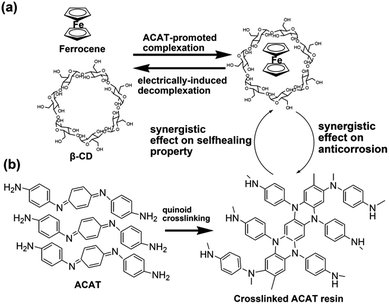
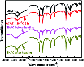
Based on the electrically-driven reversible complexation reaction between β-CD and Fc,30 the electric-induced self-healing polymer based on PGMA-Fc and bis-CD has been established in our previous work,27 and is used as the self-healable component of the SHAC material. On the other hand, ACAT is an electroactive and effective agent for anticorrosion application31–33 to be employed as the anticorrosion component of SHAC material in this work. The mixture of PGMA-FC/bis-CD and ACAT has been coated on the CRS plate surface and then react at 120 °C for 12 h. As previously reported,27 the mixture of PGMA-Fc/CD becomes insoluble after the thermal process due to the formation of Fc/β-CD based network (Fig. 1). ACAT shows an exothermic peak at about 180 °C in DSC heating scan thermogram (figure not shown here) corresponding to the self-polymerization of ACAT through the quinoid addition reaction.33,34 Nevertheless, a certain extent of the quinoid addition reaction still takes place at the processing temperature (120 °C) in this work. As the FTIR spectra shown in Fig. 2, the relative peak intensity of the quinoid ring stretching at 1600 cm−1 decreases after being heated at 120 °C for 3 h. Moreover, as PGMA-Fc still possesses some epoxide groups, the reaction between PGMA-Fc and ACAT might take place, so as to build up chemical linkages between the networks of PGMA-Fc/bis-CD and ACAT polymer. The reaction is not successfully traced with FTIR spectra comparison due to absorption overlapping. It is reasonable to point out that the obtained SHAC material could be a crosslinked polymer, rather than an interpenetrating network.The anticorrosion materials were coated on CRS plates (1.2 cm × 1.5 cm) with a thickness of about 40 μm. The samples were applied to cyclic voltammetric analysis for anticorrosion evaluation. As the Fc/β-CD complexed groups are electrically responsive, decomplexation reaction might happen to PGMA-Fc/bis-CD structure under electric treatment in the cyclic voltammetric analysis so as to result in sample detaching from the CRS plates (Fig. 3).30 Hence, the results of electrochemical analysis and anticorrosion measurement on the neat PGMA-Fc/bis-CD polymer could not be obtained in this work. Nevertheless, PGMA-Fc/bis-CD material could still bring some anticorrosion effect to CRS, even the efficiency could not be quantitative measured. As shown in Fig. 3, after anticorrosion test (immersed in 3.5 wt% NaCl(aq) for 50 h) the PGMA-Fc/bis-CD resin coated on CRS plates does not detach from the CRS surface and to show a certain extent of protection and anticorrosion ability to the CRS plates.
 | ||
| Fig. 3 PGMA-Fc/bis-CD coated CRS: (a) before and (b) after cyclic voltammetric analysis; (c) after anticorrosion test; (d) SEM micrograph of sample (c). | ||
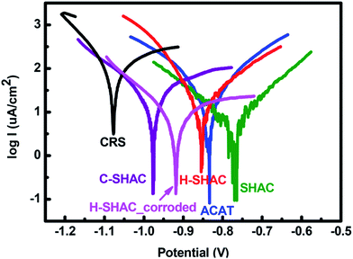
The Tafel plots measured with the anticorrosion coatings have been recorded for anticorrosion performance evaluation (Fig. 4). The recorded and calculated data is collected in Table 1. The corrosion potential (Ecorr) and corrosion current (Icorr) found with the bare CRS is −1077 mV and 101.1 μA cm−2, respectively. The corrosion rate (CR) found with CRS is 1.175 mm per year. The anticorrosion property of the neat ACAT-coated CRS could be demonstrated with the shifts of the Ecorr and Icorr to −834 mV and 50.7 μA cm−2, respectively. As a result, this sample demonstrates a CR of 0.590 mm per year and a protection efficiency (PE) of about 50%. The PE value found with the neat ACAT coating is not high. Moreover, addition of 30 wt% of PGMA-Fc/bis-CD to the polymerized-ACAT resin results in a decrease of the CR value to 0.068 mm per year so as to enhance the anticorrosion efficiency with a PE up to 94%. The result indicates that PGMA-Fc/bis-CD could act together with the polymerized-ACAT resin to exhibit a synergistic effect on anticorrosion. This synergistic anticorrosion effect of between PGMA-Fc/bis-CD and ACAT polymer could be attributed to (i) the electroactive ferrocene groups of PGMA-Fc serves as a corrosion inhibitor and adds some effectiveness of anode protection with ACAT polymer, (ii) the epoxy resin based crosslinked structure from PGMA chains enhances the adhesion strength of the SHAC material and the barrier protection efficiency to the CRS substrate.
Addition of PGMA-Fc/bis-CD to the anticorrosion coating means to impart self-healing feature to the coating, as its self-healing behaviour has been examined in the previous work.27 To perform the self-healing tests, the SHAC material coated on CRS plates were cut with a knife to generate eye-visible cutting-print. The knife-cut SHAC sample (C-SHAC) was electrically treated for 20 h with a 9 V battery to give the healed sample (H-SHAC). Under electrical treatment, the Fc/β-CD complexes dissociate due to the formation of charged ferrocene groups which dissociates rapidly from the cavity of the β-CD.30 As a result, some of the crosslinked sites of the SHAC material break. Consequently, the molecular chain mobility increase, so as being able to recovery the cutting-print. Both C-SHAC and H-SHAC samples have been applied to Tafel measurements. The anticorrosion performance of C-SHAC is relatively poor (CR: 0.286 mm per year; PE: 75%) compared to the original SHAC sample. The reduced anticorrosion performance of C-SHAC is attributed to the cutting-print portion of the CRS surface directly exposes to the testing solution without the protection of the anticorrosion coating. Corrosion initially takes place at the cutting-print and propagates to the rest portion of the CRS plates. The result is coincident to that small cracks of anticorrosion coating might significantly reduce the PE of the coating and speed up the failure occurrence. Hence, crack-healing ability is necessary for the anticorrosion coatings. It is noteworthy that the Tafel plot of the H-SHAC sample gives a CR value of 0.157 mm per year and a recovery of PE to 87%. The electrically-induced self-healing process indeed repairs the knife-cut sample and recovers the anticorrosion property of the coating. The PE-based recovery efficiency is calculated to be about 92.5%. Moreover, corrosion might occur before the healing process being applied in practical application. Therefore, the healing performance has also been examined for the condition. The C-SHAC sample after corrosion treatment was applied to the self-healing process to result in the sample coded as H-SHAC_corroded. As shown in Fig. 4, the sample still exhibits somewhat self-healing performance and give a CR value of 0.222 mm per year and a PE-based recovery efficiency of about 87%. On the other hand, the electrically-driven self-healing ability of SHAC for anticorrosion on CRS substrates has also been examined with an EIS measurement presented as the Bode plots35 shown in Fig. 5. The SHAC coating shows a high resistance in the plot to indicate its anticorrosion property over CRS substrate. While being knife-cut, an obvious decrease in the resistance appears with the sample of C-SHAC. Meanwhile, after being electrically treated to trigger the self-healing process, the corresponding healed sample (H-SHAC) shows a recovery of resistance and anticorrosion efficiency.
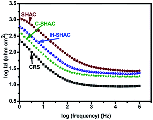 | ||
| Fig. 5 Bode plots for CRS coated with SHAC, and the corresponding knife-cut sample (C-SHAC) and the self-healed sample (H-SHAC). | ||
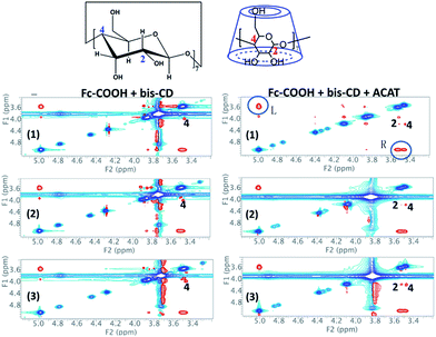
The electrically-driven healing process of the C-SHAC sample could be performed with three steps of (i) decrosslinking of the PGMA-Fc/bis-CD network with the decomplexation of Fc/β-CD groups, (ii) molecular motion to remend the cutting print, and (iii) rebuilding up the crosslinked structure of PGMA-Fc/bis-CD in the H-SHAC sample with re-complexation of Fc/β-CD groups. Usually, reformation of the Fc/β-CD complexing groups needs applying a negative potential to make the charged ferrocene groups be uncharged.30 Here the negative potential treatment has not been applied to the sample. The electroactive ACAT component is able to uncharge the ferrocene groups. As a result, the ACAT component is an effective agent to initiate the complexation reaction between Fc and β-CD groups, to rebuild up the crosslinked structure of PGMA-Fc/bis-CD component, and to promote the self-healing behaviour of the C-SHAC material. The above-mentioned effect of ACAT component has been examined with a 2D ROSEY NMR (Fig. 6).36 For the mixture of Fc-COOH and β-CD, the complexation between Fc/bis-CD could be detected with the signal arising from the interaction between the –C5H5 group of Fc and the –C(4)-H of β-CD cage. The signal intensity decreases slightly with electrically-treatment of the complexed sample due to the electrically-induced decomplexation. After removal of the electric field, a recomplexation between Fc and β-CD is not clearly observed due to applying a negative potential to uncharge the Fc group. On the other hand, addition of ACAT to the Fc-COOH and β-CD does not alter the above-mentioned Fc/bis-CD complexation signal, and results in an additional peak associating to the interaction between the –C5H5 group of Fc and the –C(2)-H of β-CD. As the –C(2)-H locates at the outer part of the β-CD cage, the appearance of this signal suggests that the electro-active ACAT might alter the electrochemical state of Fc group so as to hind the Fc group moving deeply into the β-CD cage as well as decrease the complexation strength between Fc and β-CD cage. This fact consequently is favourable for the electrically-induced decomplexation of the Fc/β-CD groups, as the electrically-treated sample show a significant decrease in the signal intensity associating to the Fc/β-CD complexes. The electroactive ACAT further helps to uncharge the charged Fc group releasing from Fc/β-CD groups, so as to promote the recomplexation of Fc/β-CD. The result is supported with the appearance of the two signals associating to the Fc/β-CD groups in the 2D ROSEY NMR spectrum. The above results and discussion support to the ACAT effect on promoting the reversible complexation–decomplexation reactions between Fc and β-CD groups. As these reactions are critical in the key steps performing the self-healing ability of the PGMA-Fc/bis-CD component, it is obvious that the ACAT polymer could work together with PGMA-Fc/bis-CD component to demonstrate the self-healing property of the prepared SHAC material.
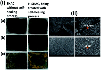
Fig. 7(I) shows the photographs of C-SHAC and H-SHAC in the anticorrosion tests, in which the sample was immersed in a 3.5 wt% NaCl aqueous solution for 50 h at 30 °C. The handmade cutting print on C-SHAC, like small cracks naturally formed on the coating, makes a small portion of CRS substrate directly exposing to the testing solution. As a result, the testing solution attacks the CRS substrate at the cutting print region and then results in a wide-range corrosion effect. Obvious portion of the SHAC coating peels off from the CRS substrate. The result indicates that small cracks would result in fatal failure for the anticorrosion coating. On the other hand, H-SHAC shows a very different result in the test. As the cutting print has been healed, H-SHAC still possesses the protective ability for the CRS substrate, and is not peeled off during the test. The SEM micrographs of the C-SHAC and H-SHAC samples after the anticorrosion tests are also collected in Fig. 7(II). For the C-SHAC sample, most portions of the coatings bulges from the surface, and some coating peels off at the crossing point of the cutting print. The results indicate that C-SHAC loses its adhesion and protective ability to the CRS substrate. Nevertheless, similar results do not appear for the H-SHAC sample. After the anticorrosion test, H-SHAC still exhibits good adhesion and coverage on the CRS substrate. Although the cutting print is still observed in the SEM micrographs of H-SHAC, and depth and width of the cutting print are relatively small compared to the original cutting prints. As a result, the electrically-driven self-healing process is effective to repair the cut/cracks of the SHAC coating, so as to recover its ability and efficiency of anticorrosion.
The adhesion between SHAC and CRS has been evaluated. The knife-cut SHAC sample was applied to a 3M tape within 10 min. After removal of the tape, the sample was subjected to SEM observation. No obvious changes are observed with the samples, indicating the good adhesion property between SHAC and CRS substrate (Fig. 8). The result demonstrates the strong adhesion of the SHAC material coated on the CRS substrate. Nevertheless, once the SHAC material is damaged, corrosion still might take place at the damage sites, propagate at the interface of the SHAC material and CRS surface, and finally result in a detachment of the SHAC coating from the CRS substrate, like the general phenomenon happening to the conventional coatings. As a result, self-healing property is critically expected for the anticorrosion coatings.
 | ||
| Fig. 8 SEM micrographs of knife-cut SHAC on CRS substrate before (upper) and after (lower) adhesion test. | ||
Conclusions
In conclusion, this work has presented a stimuli-responsive self-healing anticorrosion material. As the self-healing process could be triggered with an electrical treatment process, repairing anticorrosion coatings on metal substrates and recovery of their protective efficiency could be applied to the coatings easily, widely, and periodically. This work demonstrates a novel design concept and a new class of self-healing anticorrosion materials.Acknowledgements
The authors thank The Ministry of Science and Technology, Taiwan for the financial support on this work (Grant No. MOST 102-2221-E-007-135-MY3).Notes and references
- M. A. Malik, M. A. Hashim, F. Nabi, S. A. AL-Thabaiti and Z. Khan, Int. J. Electrochem. Sci., 2011, 6, 1927–1948 CAS.
- P. A. Sørensen, S. Kiil, K. Dam-Johansen and C. E. Weinell, J. Coat. Technol. Res., 2009, 6, 135–176 CrossRef.
- V. Sauvant-Moynot, S. Gonzalez and J. Kittel, Prog. Org. Coat., 2008, 63, 307–315 CrossRef CAS.
- H. Wei, Y. wang, J. Guo, N. Z. Shen, D. Jiang, X. Zhang, X. Yan, J. Zhu, Q. Wang, L. Shao, H. Lin, S. Wei and Z. Guo, J. Mater. Chem. A, 2015, 3, 469–480 CAS.
- E. Koh, S. Y. Baek, N. K. Kim, S. Lee, J. Shin and Y. W. Kim, New J. Chem., 2014, 38, 4409–4419 RSC.
- G. Wu, J. An, D. Sun, X. Tang, Y. Xiang and J. Yang, J. Mater. Chem. A, 2014, 2, 11614–11620 CAS.
- G. L. Li, M. Schenderlein, Y. Men, H. Möhwald and D. G. Shchukin, Adv. Mater. Interfaces, 2014, 1, 1300019 Search PubMed , 6 pages.
- M. Huang and J. Yang, J. Intell. Mater. Syst. Struct., 2014, 25, 98–106 CrossRef CAS.
- E. Koh, S. Lee, J. Shin and Y. W. Kim, Ind. Eng. Chem. Res., 2013, 52, 15541–15548 CrossRef CAS.
- D. Borisova, D. Akcakayiran, M. Schenderlein, H. Möhwald and D. G. Shchukin, Adv. Funct. Mater., 2013, 23, 3799–3812 CrossRef CAS.
- A. B. Chaudhari, P. D. Tatiya, R. K. Hedaoo, R. D. Kulkarni and V. V. Gite, Ind. Eng. Chem. Res., 2013, 52, 10189–10197 CrossRef CAS.
- P. D. Tatiya, R. K. Hadeoo, P. P. Mahulikar and V. V. Gite, Ind. Eng. Chem. Res., 2013, 52, 1562–1570 CrossRef CAS.
- T. Nesterova, K. Dam-Johansen, L. T. Pederson and S. Kiil, Prog. Org. Coat., 2012, 75, 309–318 CrossRef CAS.
- Y. González-García, S. J. García, A. E. Hughes and J. M. C. Mol, Electrochem. Commun., 2011, 13, 1094–1097 CrossRef.
- T. Nesterova, K. Dam-Johansen and S. Kiil, Prog. Org. Coat., 2011, 70, 342–352 CrossRef CAS.
- R. J. Jadhav, D. G. Hundiwale and P. P. Mahulikar, J. Appl. Polym. Sci., 2011, 119, 2911–2916 CrossRef CAS.
- L. Liao, W. Zhang, H. Wang, Y. Zhao and W. Li, Chin. Sci. Bull., 2011, 56, 439–443 CrossRef CAS.
- S. J. García, H. R. Fischer, P. A. White, J. Mardel, Y. González-García, J. M. C. Mol and A. E. Hughes, Prog. Org. Coat., 2011, 70, 142–149 CrossRef.
- M. Huang and J. Yang, J. Mater. Chem., 2011, 21, 11123–11130 RSC.
- Y. Zhao, W. Zhang, L. Liao, H. Wang and W. Li, Phys. Procedia, 2011, 18, 216–221 CrossRef CAS.
- D. O. Grigoriev, K. Köhler, E. Skorb, D. G. Shchukin and H. Möhwald, Soft Mater., 2009, 5, 1426–1432 RSC.
- M. L. Zheludkevich, D. G. Shchukin, K. A. Yasakau, H. Möhwald and M. G. S. Ferreira, Chem. Mater., 2007, 19, 402–411 CrossRef CAS.
- S. L. Lamaka, M. L. Zheludkevich, K. A. Yasakau, M. F. Montemor, P. Cecílio and M. G. S. Ferreira, Electrochem. Commun., 2006, 8, 421–428 CrossRef CAS.
- D. V. Andreeva, D. Fix, H. Möhwald and D. G. Shchukin, Adv. Mater., 2008, 20, 2789–2794 CrossRef CAS PubMed.
- G. L. Li, Z. Zheng, H. Möhwald and D. G. Shchukin, ACS Nano, 2013, 3, 2470–2478 CrossRef PubMed.
- E. B. Murphy and F. Wudl, Prog. Polym. Sci., 2010, 35, 223 CrossRef CAS.
- T. W. Chuo and Y. L. Liu, J. Polym. Sci., Part A: Polym. Chem., 2013, 51, 3395–3403 CrossRef CAS.
- S. C. Lin, C. S. Wu, J. M. Yeh and Y. L. Liu, Polym. Chem., 2014, 5, 4235–4244 RSC.
- T. I. Yang, C. W. Peng, Y. L. Lin, C. J. Weng, G. Edgington, A. Mylonakis, T. C. Huang, C. H. Hsu, J. M. Yeh and Y. Wei, J. Mater. Chem., 2012, 22, 15845–15852 RSC.
- Q. Yan, J. Yuan, Z. Cai, Y. Xin, Y. Kang and Y. Yin, J. Am. Chem. Soc., 2010, 132, 9268–9270 CrossRef CAS PubMed.
- K. Y. Huang, Y. S. Jhuo, P. S. Wu, C. H. Lin, Y. H. Yu and J. M. Yeh, Eur. Polym. J., 2009, 45, 485–493 CrossRef CAS.
- K. Y. Huang, C. L. Shiu, P. S. Wu, Y. Wei, J. M. Yeh and W. T. Li, Electrochim. Acta, 2009, 54, 5400–5407 CrossRef CAS.
- C. W. Peng, K. C. Chang, C. J. Weng, M. C. Lai, C. H. Hsu, S. C. Hsu, Y. Y. Hsu, W. I. Hung, Y. Wei and J. M. Yeh, Electrochim. Acta, 2013, 95, 192–199 CrossRef CAS.
- X. Yang, Y. Jiang, T. Zhao and Y. Yu, J. Appl. Polym. Sci., 2006, 102, 222–226 CrossRef CAS.
- A. S. Bandarenka, Analyst, 2013, 138, 5540–5554 RSC.
- J. M. Casas-Solvas, E. Ortiz-Salmerón, I. Fenández, L. Gardia-Fuentes, F. Santoyo-González and A. Vargas-Berenguel, Chem.–Eur. J., 2009, 15, 8146–8162 CrossRef CAS PubMed.
| This journal is © The Royal Society of Chemistry 2016 |

