NiCo nanotubes plated on Pd seeds as a designed magnetically recollectable catalyst with high noble metal utilisation†
S. Schaefer*a,
E.-M. Felixa,
F. Muencha,
M. Antonia,
C. Lohausa,
J. Brötza,
U. Kunza,
I. Gärtnerb and
W. Ensingera
aTechnische Universität Darmstadt, Department of Materials Science, Alarich-Weiss-Straße 2, 64287 Darmstadt, Germany. E-mail: schaefer@ma.tu-darmstadt.de; Fax: +49-6151-16-21991; Tel: +49-6151-1621996
bTechnische Universität Darmstadt, MPA/IfW Darmstadt, Grafenstraße 2, 64283 Darmstadt, Germany
First published on 18th July 2016
Abstract
Electroless plating of magnetic materials on catalytically active noble metal seeds is a powerful tool to design highly efficient recyclable catalysts. For the electroless plating procedure of metallic nanotubes in porous polymer templates, a sensitisation and activation process of the template is necessary. Therefore, metallic seeds are created on the surface of the polymer, which then enable the selective heterogeneous nucleation of a metal film on the template's surface. By choosing the metals for seeds and structures wisely, different functional materials can be purposefully combined. In this work magnetically recoverable catalysts were designed, which consist of magnetic NiCo nanotubes as carrier for catalytically active Pd seeds. The synthesised catalyst structures were thoroughly characterised by SEM, TEM, EDX, XRD, XPS, ICP-OES, VSM and then tested in the 4-nitrophenol reduction reaction, which was monitored by UV-Vis spectroscopy. After the reaction the structures were recycled and reused without a decrease in activity.
Introduction
More and more attention is drawn to topics such as sustainability and energy efficiency,1,2 which increases the focus on catalysis research. In this field, the advancements through nanotechnology open up new possibilities like increased efficiencies and decreased material costs. Nanocatalyst research uses very small particles3–5 and structures, such as tubes6–8 or wires,9,10 to improve catalytic reactions. This research field evolves quickly, and the nanoparticulate catalysts provide excellent activities, selectivities, stability and catalyst utilisation.Especially for batch syntheses, which are often used to produce chemicals on an industrial scale, nanoparticular catalysts are of great interest. Their properties are promising, based on their position between classic homogeneous and heterogeneous catalysts.11,12 A severe matter with those dispersed nanocatalysts is the segregation and recovery as it is known from homogeneous catalysts due to their small size.1 Conventional separation techniques such as filtration are not efficiently working for finely dispersed nanostructures. Therefore, it is necessary to immobilise the structures or use new efficient recycling and separation strategies. This obstacle can be overcome by using ferromagnetic structures made from e.g. Ni, Co, or Fe, which can be recovered or recollected by applying a magnetic field.13–15 Those structures can act as catalysts by themselves16 or they can be used as support for metal nanoparticles with a higher catalytic activity. Depending on the reaction, different ferromagnetic support nanomaterials can be combined with active nanoparticles into new catalyst materials. For the reduction of 4-nitrophenol (4-NP) to 4-aminophenol (4-AP), especially noble metals prove to be efficient catalyst, such as Pt,17,18 Pd,4,19–24 Au,23,25–28 and Ag.29–31 Especially Pd nanomaterials show high activities towards the reduction of 4-NP.23,24 Those metals are also known as possible seeding materials for the electroless plating method.24,32
Electroless plating is based on the surface-selective conversion of a metastable redox pair, which leads the autocatalytic growth of a metal film. To initiate the reaction, seeding particles are usually required on the surface to be plated. Those seeds need to be catalytically active to oxidise the reducing agent. Therefore, it is necessary to have different seed materials for differently composed plating solutions. For example, a plating solution containing borane dimethylamine complex (DMAB) as reducing agent can easily be triggered by Ni or Co seeds, directly followed by Pd as seed material.33
In this study, we describe the design of a semi-heterogeneous catalyst tailored for the batch hydrogenation of 4-NP, which is of high industrial relevance for the synthesis of the painkiller paracetamol, also known as acetaminophen. High catalytic activity is ensured by the use of Pd as the active material, which is integrated in the easily accessible outer surface of NiCo nanotubes (NTs) to achieve efficient noble metal utilisation. In addition, due to its ferromagnetism, the nanotube support renders the material's bifunctionality and allows for a convenient catalyst recycling.
Fort the first time, we show that the seeding step in electroless plating can be used to create high-performing multifunctional metal nanotube catalysts with reduced noble metal content. Usually, the seed particles are just used to initialise the deposition reaction and have no further application advantage.2,34–36 Here, a double benefit is achieved. First, the nanoparticles enable the formation of their own carrier, then they act as catalyst towards the hydrogenation of 4-NP on the recollectable support.
Experimental
General and chemicals
The glassware was cleaned with nitric acid and aqua regia before usage. All solutions were freshly prepared with Milli-Q water (>18 MΩ cm at room temperature). The following chemicals were used without further purification:4-Nitrophenol (Fluka, puriss., p.a.), cobalt(II) sulphate heptahydrate (Sigma, 99.0%), dichloromethane (Promchem, 99.8%), borane dimethylamine complex (Aldrich, pur 97%), ethanol (Labor Service GmbH, p.a.), potassium chloride (Merck, pur 99,5%), nickel(II) sulphate heptahydrate (Sigma, 99,0%), methanol (AppliChem, pure Ph. Eur.), palladium(II) chloride (Sigma, 99.9%), sodium borohydride (Merck, for synthesis), sodium hydroxide 32% in water (Sigma Aldrich, purum), tin(II) chloride (Merck, for synthesis), trifluoroacetic acid (Riedel-de Haën, >99%), sodium citrate dihydrate (Sigma, puriss.).
Template preparation
For the metal NT synthesis, ion-track etched polycarbonate membranes are used as template. The track etching process is explained in detail in the literature.37 In the present case, 30 μm thick polycarbonate foils (Makrofol® from Bayer Material Science AG) were irradiated with Au ions (kinetic energy: 11.4 MeV per nucleon; fluence: 108 ions cm−2) at the GSI Helmholtzzentrum für Schwerionenforschung GmbH (Darmstadt), followed by etching at 50 °C in 6 M stirred sodium hydroxide solution for 20 min. This procedure creates cylindrical pores of approximately 650 nm in diameter. The prepared template was washed with water and dried.Sensitisation, activation and electroless metal plating
The as-prepared PC template was immersed in a sensitisation solution for 45 min (42 mM SnCl2 and 71 mM trifluoroacetic acid in methanol and water (1![[thin space (1/6-em)]](https://www.rsc.org/images/entities/char_2009.gif) :
:![[thin space (1/6-em)]](https://www.rsc.org/images/entities/char_2009.gif) 1)), then washed with ethanol and transferred to a Pd activation solution for 4 min (11.3 mM PdCl2, 33.9 mM KCl and water). This process is repeated another two times, in which the sensitisation duration is reduced to 15 min. After the activation process, the template was washed with ethanol and water and then placed in the electroless NiCo plating solution (100 mM NiSO4·7H2O, 10 mM CoSO4·7H2O, 100 mM sodium citrate dihydrate, 100 mM DMAB and water) for 120 min at room temperature. Subsequently, the template was washed with water and dried.
1)), then washed with ethanol and transferred to a Pd activation solution for 4 min (11.3 mM PdCl2, 33.9 mM KCl and water). This process is repeated another two times, in which the sensitisation duration is reduced to 15 min. After the activation process, the template was washed with ethanol and water and then placed in the electroless NiCo plating solution (100 mM NiSO4·7H2O, 10 mM CoSO4·7H2O, 100 mM sodium citrate dihydrate, 100 mM DMAB and water) for 120 min at room temperature. Subsequently, the template was washed with water and dried.
Characterisation
The morphology of the NiCo NTs was investigated by scanning electron microscopy (SEM) (Philips, Model XL 30 FEG, 15 kV acceleration voltage) and transmission electron microscopy (TEM) (FEI, CM 20 ST, 200 kV acceleration voltage). For the SEM characterisation the polymer matrix was dissolved in dichloromethane and the template-free NiCo NTs were then collected on Si wafer pieces. Whereas, for the TEM analysis, the samples are embedded in Araldite 502R at 60 °C, cut to slices of ≈50 nm thickness with an ultramicrotome, and mounted on copper grids.The composition of the NTs is determined by energy dispersive X-ray spectroscopy (EDX) (EDAX Genesis) which is integrated in the SEM setup.
X-ray diffraction (XRD) measurements were conducted with a Stoe Stadi P diffractometer using a Ge(111)-monochromator on the primary side to select the Mo-Kα1-radiation. The NiCo NTs were measured within the polymer template in transmission geometry with a step width of 0.01°.
X-ray photoelectron spectra were recorded on a PHI 5700 spectrometer (Physical Electronics) with a monochromatic Al-Kα radiation (hν = 1486.6 eV). High resolution spectra were obtained with a pass energy of 5.85 eV. The energy resolution has been determined from the Gaussian broadening of a sputter cleaned Ag sample to be ≈400 meV. Calibration of the binding energies was achieved by adjusting to the Ag 3d5/2- (=EB 368.26 eV (ref. 38)) and Cu 2p3/2-core levels (=EB 932.67 eV (ref. 38)) and the Ag Fermi-edge from freshly sputter cleaned samples. For XPS characterisation, the tubes were collected template-free on a Si wafer.
For the determination of the exact Pd content of the structures inductively coupled plasma optical absorption spectroscopy (ICP-OES) is conducted (PerkinElmer OPTIMA 2000 DV). A defined amount of template freed metal nanostructures (10 mg) is dissolved in 1 ml of freshly prepared aqua regia, thoroughly boiled and diluted with water prior to the measurement.
The magnetic properties of the sample were measured by using a vibrating-sample magnetometer (VSM). A template square with an edge length of 5 mm was deployed. The NTs were characterised still embedded in the polymer matrix. The magnetic properties were characterised parallel and perpendicular to the tube axis at room temperature and with external magnetic fields of 20 kOe.
The reduction of 4-NP by NaBH4 was traced by UV-Vis spectroscopy (Perkin Elmer Lambda 900). The UV-Vis spectra were recorded by using a scan rate of 655 nm min−1 and a spectral range from 250 nm to 500 nm. The reaction solution was composed of 0.2 mL freshly prepared aqueous solution of NaBH4 (15 mM) and 2.8 mL of 4-NP solution (0.05 mM). The catalytic activity of NiCo NTs with Pd seeds was evaluated by immersing the template-free tubes in the reaction solution and measuring the light absorbance over the reaction time. The experiment was carried out at 25 °C and repeated five times to prove the recyclability using a small permanent magnet.
Results and discussion
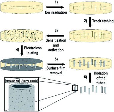
The deposition of NiCo NT was carried out by an electroless plating procedure onto an ion-track etched polycarbonate membrane. The whole process is shown in detail in Fig. 1. The first and second step in Fig. 1 describe the preparation of the template by ion irradiation and subsequent track etching. In step three, the sensitisation and activation of the template takes place through creation of metallic seed particles on the template surface.After that, the metal deposition of the metal film takes place (step 4) by immersing the activated template in the deposition solution. Before the template is dissolved (step 6), the metallic surface film has to be removed (step 5) so that tubes are freed from the template matrix and singularised.
For the synthesis of magnetic NiCo NTs Pd seed particles are used. This has two reasons: (i) Pd seed particles are excellent catalysts for the electroless plating solutions with DMAB as reducing agent33 and (ii) Pd is also particularly active in the 4-NP reduction and therefore very promising for the aimed application.23,24
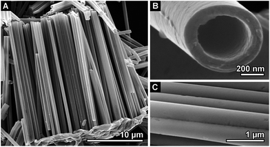
The isolated nanostructures are then characterised by high resolution SEM to determine their morphology as presented in Fig. 2. The deposited NTs were grown through the whole template and therefore have a length of 30 μm as it can be seen in Fig. 2A. The tube diameter is approximately 650 nm, which corresponds to the pore diameter of the template. The wall thickness of the tubes is dependent on the deposition time.
After 120 min a thickness of 100 nm is reached (Fig. 2B). As shown in Fig. 2C, the walls of those NTs are very homogeneous and smooth. The original Pd seeding particles cannot be visualised by SEM or by TEM (Fig. S1 in the ESI†), due to the wall thickness of the structure and the small amount of Pd. Thus, we can state that the Pd nanoparticles are firmly embedded in the outer tube wall, which is beneficial for catalyst stability.
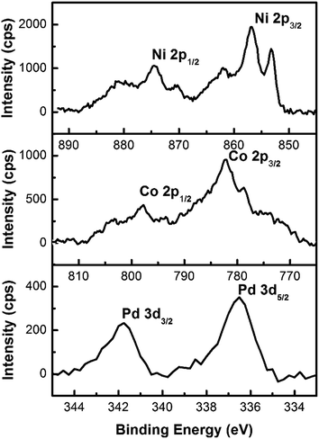
In addition a composition analysis by EDX is unable to detect the Pd in the material (Fig. S2 in the ESI†), due to the small amount of Pd in comparison to Ni and Co. Only a slightly increased background signal in the area of 1.5 keV to 6 keV could be connected to the presence of the seed material. As a result of this measurement, the composition of the tubes is determined to be Ni68Co32. But the Pd seeds have to be still present on the surface of the NTs, because Pd cannot be galvanically replaced by Ni as it is possible for e.g. Ag seeds in a Au plating solution.39 Hence, surface sensitive XPS measurements were conducted to get more information regarding the remaining seeds on the surface of the NTs. Thus, the presence of Pd on the surface could be proven. The detailed spectra of the Ni 2p-, Co 2p- and Pd 3d-peak were recorded as shown in Fig. 3. The composition of the nanotube surface is determined by integration of the peaks; 59.7 at% Ni, 37.9 at% Co and 2.4 at% Pd. A precise analysis of the species which are present is hard to make due to an overall signal shift, which is caused by the poor electrical contact of the tubes with the substrate. But in the case of Ni and Co different oxidation states are present in the material, most likely elemental Ni and Co as well as different oxides.2,40
Furthermore, the presence of a small amount of boron is expected as a result of the utilisation of DMAB as reducing agent.41 Since no boron could be detected in EDX as well as XPS, XRD measurements were conducted to determine the phase composition of the NTs. In Fig. 4 the diffractogram is shown.
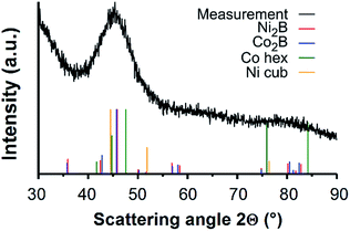 | ||
| Fig. 4 XRD measurement of the NTs inside the template. The broad reflex corresponds to a nanocrystalline or semi-amorphous structure of different phases. | ||
A broad reflex between 35° and 50° appears within the amorphous background signal. The broadness of the reflex indicates a nanocrystalline structure of NTs with crystal sizes below 10 nm. This reduction of crystallinity is typical for electroless deposited Ni structures and films for which DMAB was used as reducing agent.2,42 Comparison of the obtained diffractogram with the standard reflex positions of Ni2B (PDF-2 card 25-576), Co2B (PDF-2 card 25-241), hexagonal Co (PDF-2 card 1-1278) and cubic Ni (PDF-2 card 65-380) shows that the measured curve cannot be explained by Ni and Co alone (Fig. 4). The reflex maximum appears at an angle of 45°, which is neither fitting the expected position of elemental Ni nor Co. The clear assignment of the broad reflex is difficult, because all considered phases are present beneath it. This indicates the simultaneous presence of several phases. Hence, borides in the form of Ni 2B and Co 2B could be present as well as elemental Ni and Co.
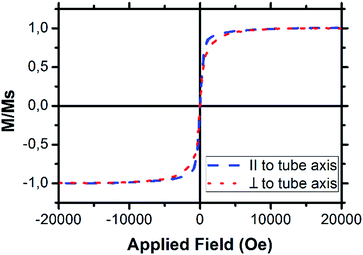
To determine the magnetic properties of those NTs VSM measurements were conducted in which an array of tubes was measured inside the template parallel and perpendicular to the tube axis. The recorded hysteresis loops are shown in Fig. 5. There is a slight difference in the magnetic properties depending on the measurement direction. This difference is caused by shape anisotropy and appears in structures of high aspect ratio.43,44 Hence, a magnetic hard and easy axis can be determined. In the case of the NTs the magnetically hard axis is perpendicular to the tubes whereas the easy axis is parallel to the tube axis.
Besides the NiCo NTs, Ni NTs were synthesised and characterised by the same methods, but those tubes show paramagnetic behaviour (Fig. S3 in the ESI†).45,46 Therefore, it was necessary to introduce Co into the structures for the design of a magnetic nanocatalyst, that can be efficiently recollected.
Catalytic activity of the structures
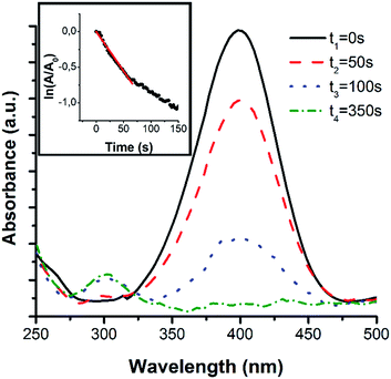
The catalytic performance and recyclability of the NiCo NTs is tested in the hydrogenation of 4-NP. This reaction can easily be monitored by UV-Vis spectroscopy due to a distinctive absorption peak of the educts at 400 nm and the products at 295 nm. The reaction is kinetically inhibited and only takes place in the presence of a suitable catalyst.23First, 0.7 mg of the NiCo NTs were dispersed in 4-NP solution. It shows a pale yellow colour with an absorbance peak at 317 nm. By adding NaBH4, the colour of the solution changes to an intense yellow. The absorbance peak shifts to 400 nm, which corresponds to the formation of 4-nitrophenolate ions in the now alkaline solution. When all three components are mixed together the reduction reaction directly starts and the yellow colour begins to vanish, which leads to the evolution of an absorbance peak at 295 nm, due to the presence of 4-AP. By recording the absorption spectra at the beginning of the reduction reaction and at further points in time, it is possible to monitor the time-dependent educt conversion (Fig. 6). To determine the rate constant of this reaction, the absorbance of the educt-related peak at 400 nm was measured every 3 s and normalised to the initial absorbance (A0). This resulting curve is shown in the inset in Fig. 6. Using this data, the apparent rate constant, which corresponds to the slope of the linear regime, can be calculated.23,47 In our case, the apparent rate constant is obtained as 9.64 × 10⁻³ s−1. This rate constant is higher than the one of Ni–Co–Pd–P composites (7.9 × 10⁻³ s−1), which were synthesised through a hydrothermal method,22 as well as for palladium/polypyrrole nanocapsules, which have a rate constant of about 8.87 × 10⁻³ s−1.20 The mass specific rate constant is 13.77 s−1 g−1.
To determine the relative contributions of the magnetic support and the Pd seeds to the catalyst performance, a control experiment with electrodeposited NiCo nanowires (NWs) was conducted. The structure needed to be synthesised without seeding particles. Accordingly, electrodeposition is a good choice, because the structures are grown from a conductive back electrode inside the template and therefore no seed particles are required. Those NWs showed nearly no activity towards the 4-NP reduction reaction. After 30 min reaction time, a slight decrease in absorbance at a wavelength of 400 nm can be observed (Fig. S4 in the ESI†). This observation is in agreement with previous reports, which find the specific activity of Ni and Co low as compared to that of noble metals such as Pd.24,48 Hence, the Pd seeding particles contribution determines the catalytic activity of the NTs.
Due to the fact, that mainly the Pd seeds are causing the catalytic activity the effective rate constant has to be normalised only to the amount of Pd, which could be determined by ICP-OES. The Pd content amounts to 0.62 μg. For comparison, the sample further consists of 108.12 μg Co and 499.01 μg Ni. The amount of Pd is marginal. Concerning this value for the Pd mass the effective rate constant with respect to the Pd mass can be calculated as 1.54 × 10⁴ s−1 gPd−1.
This tremendous activity surpasses the activity of other supported Pd-nanoparticle catalyst systems.49,50 Potential reasons for this could be synergetic effects of the multimetallic system51–53 or the lack of protecting ligands.54
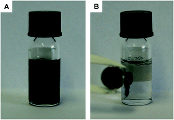
Besides this tremendous activity, it is also possible to recollect those tubes by applying a magnetic field (see Fig. 7), which enables the reuse of the catalyst several times. In this study, the catalyst was recycled and reused without any decrease in activity (Fig. S5 in the ESI†).
Compared to catalytic nanostructures based on noble metals, the presented NT catalyst has two major advantages. First, the rate constant based on the amount of noble metal is markedly higher than for other catalyst systems, such as bimetallic Au/Ag52 nanostructures, which have a rate constant of 10.1 s−1 g−1 or Au dendrites which were grown by galvanic replacement on prickly Ni nanowires, which have a rate constant of 0.875 s−1 g−1.55 Secondly, the magnetic support structure creates the opportunity to recollect the catalytic structures and reuse them.
To determine whether the nanotube is a favourable shape for those catalytic structures, a thin film with Pd nanoparticles on top is prepared by the same synthesis route. Even so, the film has a similar amount of Pd nanoparticles (0.73 μg), there is nearly no activity towards the reduction of 4-NP (Fig. S6 in the ESI†). While the prepared film is a heterogeneous catalyst the nanotubes act more like a semi-homogenous catalyst system, due to the excellent structure distribution, as it is described by Polshettiwar et al. and Schätz et al.1,15
Conclusions
The combination of a magnetic support structure and catalytically active nanoparticles on top creates a recollectable and highly active catalyst. This material could be synthesised solely with simple and flexible wet-chemical deposition methods. The multifunctional structures are used as an efficient catalyst for the reduction of 4-NP. To analyse the influence of the magnetic support structure on the catalytic activity, electrodeposited NiCo NWs were tested as a Pd-free reference material in the same reaction. Those wires show nearly no activity towards the 4-NP reduction reaction, therefore, the high activity of the NTs can be ascribed to the embedded Pd seeds.By comparing the catalyst with a thin film of the same composition, it was verified that the nanotubular shape contributes to the extraordinary activity of the system. The Pd-normalised rate constant for the nanotube catalyst of 1.54 × 10⁴ s−1 gPd−1 surpasses existing systems, while the magnetic support allows facile catalyst recycling. This increases the cost efficiency and decreases the overall material costs.
On grounds of the versatility of the used metal deposition technique, highly variable types of bi- or multi-metallic and multi-functional nanostructures for other catalytic reactions can be synthesised in the same manner.
Acknowledgements
The authors thank Prof. Ch. Trautmann (GSI Helmholtzzentrum for Heavy Ion Research) for support with the irradiation experiments. Furthermore, we thank the group of Prof. O. Gutfleisch for the magnetic measurements and Prof. J. J. Schneider for the access to the UV-Vis spectrometer. The authors gratefully acknowledge funding by the LOEWE project RESPONSE of the Hessen State Ministry of Higher Education, Research and the Arts (HMWK). S. S. thanks Bastian Paulsen for his assistance with the syntheses.References
- V. Polshettiwar, R. Luque, A. Fihri, H. Zhu, M. Bouhrara and J.-M. Basset, Chem. Rev., 2011, 111, 3036–3075 CrossRef CAS PubMed.
- F. Muench, M. Oezaslan, M. Rauber, S. Kaserer, A. Fuchs, E. Mankel, J. Brötz, P. Strasser, C. Roth and W. Ensinger, J. Power Sources, 2013, 222, 243–252 CrossRef CAS.
- Z. Jiang, J. Xie, D. Jiang, X. Wei and M. Chen, CrystEngComm, 2013, 15, 560–569 RSC.
- A. M. Kalekar, K. K. K. Sharma, M. N. Luwang and G. K. Sharma, RSC Adv., 2016, 6, 11911–11920 RSC.
- K. R. Rasmi, S. C. Vanithakumari, R. P. George, C. Mallika and U. K. Mudali, RSC Adv., 2015, 5, 108050–108057 RSC.
- Y. Xiao, Q. Lv, J. Zhu, S. Yao, C. Liu and W. Xing, RSC Adv., 2014, 4, 21176–21179 RSC.
- G. Zhang, S. Sun, M. Cai, Y. Zhang, R. Li and X. Sun, Sci. Rep., 2013, 3, 1526–1533 Search PubMed.
- E.-M. Felix, F. Muench and W. Ensinger, RSC Adv., 2014, 4, 24504–24510 RSC.
- Y. Imura, K. Tsujimoto, C. Morita and T. Kawai, Langmuir, 2014, 30, 5026–5030 CrossRef CAS PubMed.
- S. M. Choi, J. H. Kim, J. Y. Jung, E. Y. Yoon and W. B. Kim, Electrochim. Acta, 2008, 53, 5804–5811 CrossRef CAS.
- R. Porta, M. Benaglia and A. Puglisi, Org. Process Res. Dev., 2016, 20, 2–25 CrossRef CAS.
- Y.-L. Fang, K. N. Heck, P. J. J. Alvarez and M. S. Wong, ACS Catal., 2011, 1, 128–138 CrossRef CAS.
- S. Shylesh, V. Schünemann and W. R. Thiel, Angew. Chem., 2010, 122, 3504–3537 CrossRef.
- S. Behrens, Nanoscale, 2011, 3, 877–892 RSC.
- A. Schätz, O. Reiser and W. J. Stark, Chemistry, 2010, 16, 8950–8967 CrossRef PubMed.
- A. Wang, H. Yin, H. Lu, J. Xue, M. Ren and T. Jiang, Catal. Commun., 2009, 10, 2060–2064 CrossRef CAS.
- Y. Rong, A. Dandapat, Y. Huang, Y. Sasson, L. Zhang, L. Dai, J. Zhang, Z. Guo and T. Chen, RSC Adv., 2016, 6, 10713–10718 RSC.
- D. He, C. Zeng, C. Xu, N. Cheng, H. Li, S. Mu and M. Pan, Langmuir, 2011, 27, 5582–5588 CrossRef CAS PubMed.
- J. Sun, Y. Fu, G. He, X. Sun and X. Wang, Catal. Sci. Technol., 2014, 4, 1742–1748 CAS.
- Y. Xue, X. Lu, X. Bian, J. Lei and C. Wang, J. Colloid Interface Sci., 2012, 379, 89–93 CrossRef CAS PubMed.
- H. Li, L. Han, J. Cooper-White and I. Kim, Green Chem., 2012, 14, 586–591 RSC.
- P. Yang, A. D. Xu, J. Xia, J. He, H. L. Xing, X. M. Zhang, S. Y. Wei and N. N. Wang, Appl. Catal., A, 2014, 470, 89–96 CrossRef CAS.
- P. Zhao, X. Feng, D. Huang, G. Yang and D. Astruc, Coord. Chem. Rev., 2015, 287, 114–136 CrossRef CAS.
- F. Muench, M. Oezaslan, I. Svoboda and W. Ensinger, Mater. Res. Express, 2015, 2, 105010–105021 CrossRef.
- Y. Zhang, Z. Cui, L. Li, L. Guo and S. Yang, Phys. Chem. Chem. Phys., 2015, 17, 14656–14661 RSC.
- K. Kuroda, T. Ishida and M. Haruta, J. Mol. Catal. A: Chem., 2009, 298, 7–11 CrossRef CAS.
- Y.-C. Chang and D.-H. Chen, J. Hazard. Mater., 2009, 165, 664–669 CrossRef CAS PubMed.
- M. Rocha, C. Fernandes, C. Pereira, S. L. H. Rebelo, M. F. R. Pereira and C. Freire, RSC Adv., 2015, 5, 5131–5141 RSC.
- W. Zhang, F. Tan, W. Wang, X. Qiu, X. Qiao and J. Chen, J. Hazard. Mater., 2012, 217–218, 36–42 CAS.
- Q. Geng and J. Du, RSC Adv., 2014, 4, 16425–16428 RSC.
- F. Muench, M. Rauber, C. Stegmann, S. Lauterbach, U. Kunz, H.-J. Kleebe and W. Ensinger, Nanotechnology, 2011, 22, 415602–415610 CrossRef PubMed.
- F. Muench, A. Eils, M. E. Toimil-Molares, U. H. Hossain, A. Radetinac, C. Stegmann, U. Kunz, S. Lauterbach, H.-J. Kleebe and W. Ensinger, Surf. Coat. Technol., 2014, 242, 100–108 CrossRef CAS.
- I. Ohno, O. Wakabayashi and S. Haruyama, J. Electrochem. Soc., 1985, 132, 2323–2330 CrossRef CAS.
- P. Shao, G. Ji and P. Chen, J. Membr. Sci., 2005, 255, 1–11 CrossRef CAS.
- M. A. Sanchez-Castillo, C. Couto, W. B. Kim and J. A. Dumesic, Angew. Chem., Int. Ed., 2004, 43, 1140–1142 CrossRef CAS PubMed.
- Y.-G. Zhou, S. Yang, Q.-Y. Qian and X.-H. Xia, Electrochem. Commun., 2009, 11, 216–219 CrossRef CAS.
- P. Y. Apel and S. N. Dmitriev, Adv. Nat. Sci.: Nanosci. Nanotechnol., 2011, 2, 013002–013009 CrossRef.
- J. Moulder, W. Stickle, P. Sobol and K. Bomben, Handbook of X-ray photoelectron spectroscopy, Physical Electronics, Inc., Eden Prairie, 1995 Search PubMed.
- R. J. Gilliam, S. J. Thorpe and D. W. Kirk, J. Appl. Electrochem., 2007, 37, 233–239 CrossRef CAS.
- C. Lohaus, J. Morasch, J. Brötz, A. Klein and W. Jaegermann, J. Phys. D: Appl. Phys., 2016, 49, 155306–155312 CrossRef.
- J. Sudagar, J. Lian and W. Sha, J. Alloys Compd., 2013, 571, 183–204 CrossRef CAS.
- S. Arai, Y. Imoto, Y. Suzuki and M. Endo, Carbon, 2011, 49, 1484–1490 CrossRef CAS.
- S. L. Viñas, R. Salikhov, C. Bran, E. M. Palmero, M. Vazquez, B. Arvan, X. Yao, P. Toson, J. Fidler, M. Spasova, U. Wiedwald and M. Farle, Nanotechnology, 2015, 26, 415704–415712 CrossRef PubMed.
- D. L. Leslie-Pelecky and R. D. Rieke, Chem. Mater., 1996, 8, 1770–1783 CrossRef CAS.
- L. F. Kiss, I. Bakonyi, A. Lovas, M. Baran and J. Kadlecová, Phys. Rev. B, 2001, 64, 0644171–0644177 CrossRef.
- A. M. Bratkovsky, S. N. Rashkeev, A. V Smirnov and G. Wendin, Europhys. Lett., 1994, 26, 43–49 CrossRef CAS.
- P. Hervés, M. Pérez-Lorenzo, L. M. Liz-Marzán, J. Dzubiella, Y. Lu and M. Ballauff, Chem. Soc. Rev., 2012, 41, 5577–5587 RSC.
- C. Wang, R. Ciganda, L. Salmon, D. Gregurec, J. Irigoyen, S. Moya, J. Ruiz and D. Astruc, Angew. Chem., Int. Ed., 2016, 55, 3091–3095 CrossRef CAS PubMed.
- S. Harish, J. Mathiyarasu, K. L. N. Phani and V. Yegnaraman, Catal. Lett., 2009, 128, 197–202 CrossRef CAS.
- X. Wu, C. Lu, W. Zhang, G. Yuan, R. Xiong and X. Zhang, J. Mater. Chem. A, 2013, 1, 8645–8652 CAS.
- H.-L. Jiang, T. Akita, T. Ishida, M. Haruta and Q. Xu, J. Am. Chem. Soc., 2011, 133, 1304–1306 CrossRef CAS PubMed.
- J. Huang, S. Vongehr, S. Tang, H. Lu, J. Shen and X. Meng, Langmuir, 2009, 25, 11890–11896 CrossRef CAS PubMed.
- H. F. Zarick, W. R. Erwin, J. Aufrecht, A. Coppola, B. R. Rogers, C. L. Pint and R. Bardhan, J. Mater. Chem. A, 2014, 2, 7088–7098 CAS.
- Y. Lu, Y. Wang and W. Chen, J. Power Sources, 2011, 196, 3033–3038 CrossRef CAS.
- S. Sarkar, A. K. Sinha, M. Pradhan, M. Basu, Y. Negishi and T. Pal, J. Phys. Chem. C, 2011, 115, 1659–1673 CAS.
Footnote |
| † Electronic supplementary information (ESI) available: For further characterisation of the sample. See DOI: 10.1039/c6ra10235b |
| This journal is © The Royal Society of Chemistry 2016 |

