Surface passivation of boron emitters on n-type c-Si solar cells using silicon dioxide and a PECVD silicon oxynitride stack
Nagarajan Balajia,
Seunghwan Leeb,
Cheolmin Parka,
Jayapal Rajab,
Huong Thi Thanh Nguyenb,
Somenath Chatterjee†
c,
K. Nikeshd,
R. Jeyakumar†e and
Junsin Yi*ab
aDepartment of Energy Science, Sungkyunkwan University, 300 Cheoncheon-dong, Jangan-gu, Suwon, Gyeonggi-do 400-746, Republic of Korea. E-mail: yi@yurim.skku.ac.kr
bCollege of Information and Communication Engineering, Sungkyunkwan University, 300 Cheoncheon-dong, Jangan-gu, Suwon, Gyeonggi-do 400-746, Republic of Korea
cDepartment of Electronics and Communication Engineering, Sikkim Manipal Institute of Technology, Sikkim Manipal University, Sikkim 737102, India
dDepartment of Electrical and Electronics Engineering, Rajalakshmi Engineering College, Anna University, Chennai-602105, India
ePhysics of Energy Harvesting Division, CSIR-National Physical Laboratory, New Delhi 110 012, India
First published on 19th July 2016
Abstract
Recombination of charge carriers is a significant loss mechanism in solar cells. To achieve high efficiency, recombination losses should be minimized. The surface passivation technique is used to minimize recombination losses. Also, surface passivation is essential to achieve high conversion efficiency, especially for thin crystalline-Si (c-Si) wafers. We have investigated the passivation properties of a silicon oxynitride (SiOxNy)/silicon dioxide (SiO2) stack for boron doped emitters. SiOxNy single layer properties were optimized using various gases (N2O, NH3 and SiH4) and gas flow ratios. Optimized SiOxNy films resulted in low refractive indices ranging from 1.49 to 1.64. FTIR spectroscopy was used to analyze the chemical composition of the SiOxNy films. As the gas flow ratio increases, the absorbance peaks shift towards higher wave numbers due to an increase in oxygen concentration in the film with a decrease in refractive index. After optimization, SiOxNy film was capped over with a 10 nm thermal SiO2 layer. The effective lifetime of the SiOxNy/SiO2 stack was found to be 0.690 ms. Light I–V results showed an efficiency of 19.58% with Voc, Jsc and fill factor of 644 mV, 37 mA cm−2 and 82.3%, respectively. The role of SiOxNy/SiO2 stack passivation for the improvement of solar cell efficiency is discussed.
1. Introduction
One of the vital issues for enhancing the efficiency of c-Si solar cells is reducing the loss of electron–hole pairs due to surface recombination. Recombination losses can be minimized by reducing defect states at the c-Si surface using chemical passivation, and/or field effect passivation.1 Also, at the c-Si/metal interface, the presence of a large number of defect states results in recombination losses. One of the best approaches to electronically isolate the metal contact from the c-Si wafer is to insert an ultra-thin insulator film structure to passivate the interface and to reduce recombination losses. The most common materials used for passivation are thermally grown SiO2,2,3 plasma-enhanced chemical vapor deposited (PECVD) hydrogenated amorphous silicon nitride (a-SiNx:H),4,5 hydrogenated amorphous silicon (a-Si:H) grown by PECVD,6 and atomic layer deposited (ALD) aluminum oxide (Al2O3)7 layers. Recently, n-type c-Si solar cells have been reviewed,8 and their advantages are reported.8–10 Conventional a-SiNx:H (hereafter called SiNx) passivation used for boron diffused p+-emitter in n-type c-Si cells results in poor passivation.11 Hence a new way of passivation and anti-reflection coating is required for p-type emitter. Nevertheless, Al2O3 layer is normally used for p-type emitter, which is not thermally stable and its anti-reflection property has to be improved further.11 Stacked passivation layer on p-type emitter such as SiNx/SiO2/p-type emitter is preferred for high efficiency solar cell; SiNx over p-type emitter is not suitable due to the formation of an inversion layer.7,11,12SiOxNy films have also been widely used for anti-reflection coating and passivation to enhance the efficiency of solar cells. Since the SiOxNy film possesses the properties of both SiNx (chemical inertness) and SiO2 (low permeability) with variable refractive index (n) and low absorbance, it is a suitable anti-reflection material for solar cells.13 Stack of anti-reflection layers employing SiOxNy layer such as SiOxNy/SiO2/p+-type boron emitter/n-type c-Si provide better transmission coefficients and thus the increase in short circuit current by increasing photon absorption in the cell.
In this study, initially SiOxNy single layer properties were optimized and then SiOxNy film was capped over a 10 nm thermal SiO2 layer. We have investigated the passivation properties of SiOxNy/SiO2 stack structure for n-type c-Si solar cells.
2. Experimental details
n-Type, Cz, 〈100〉 oriented c-Si wafer with a thickness of ∼200 μm and resistivity around 1–3 Ω cm was used to study the passivation properties of SiOxNy film and device fabrication. A 〈100〉 oriented n-type prime grade single side polished c-Si wafer with a resistivity of 1–10 Ω cm was used for SiOxNy refractive index, and compositional measurements.2.1 Wafer cleaning and SiOxNy deposition
Radio Corporation of America (RCA) 1 and 2 cleaning procedure was followed to remove organic and metallic impurities respectively. Prior to the deposition of SiOxNy films, wafers were cleaned by dipping in 1% diluted hydrofluoric acid (HF) solution to remove the native oxide layer formed on c-Si during RCA-1 cleaning.The SiOxNy films were deposited on cleaned n-type c-Si wafer using a remote PECVD reactor with radio frequency (RF) of 13.56 MHz. The deposition parameters, viz. temperature, RF power and process pressure were maintained at 275 °C, 300 W and 1 Torr, respectively. Ammonia (NH3), nitrous oxide (N2O) and silane (SiH4) were used as a precursor (process) gases. In order to deposit SiOxNy films with different compositions, the gas flow ratio of the precursor gases (R = N2O/(N2O + NH3)) was varied by fixing SiH4 gas flow rate of 45 sccm. During the deposition, process gas flow ratio and temperature were kept constant. The deposition rate of SiOxNy films was 30 nm min−1.
2.2 Quality of surface passivation
The passivation quality of the SiOxNy films is evaluated in terms of the effective minority carrier lifetime (τeff). Here the term “effective” minority carrier lifetime (hereafter minority carrier lifetime or τeff) includes both surface and bulk components. For minority carrier lifetime measurements, SiOxNy films were deposited on both sides of the wafer (Fig. 1a). τeff is determined as a function of the excess carrier density by means of photoconductance decay (PCD) measurement (model: WCT-120, Sinton Instruments, USA). Thermal oxide (SiO2) was grown in dry oxidation ambient by flowing oxygen gas at a temperature around 900 °C. Prior to the deposition, all wafers were thoroughly cleaned using 1% diluted HF to remove the native oxide layer. To calculate the trapped charges present in the passivated SiOxNy layer, metal (Al)/insulator (SiOxNy)/semiconductor (n-type c-Si) structure, known as MIS structure, was fabricated. Capacitance–voltage (C–V) measurements were performed using HP 4192A impedance analyzer. The flat-band voltage was calculated from the measured C–V curves for different gas flow ratios used for SiOxNy deposition.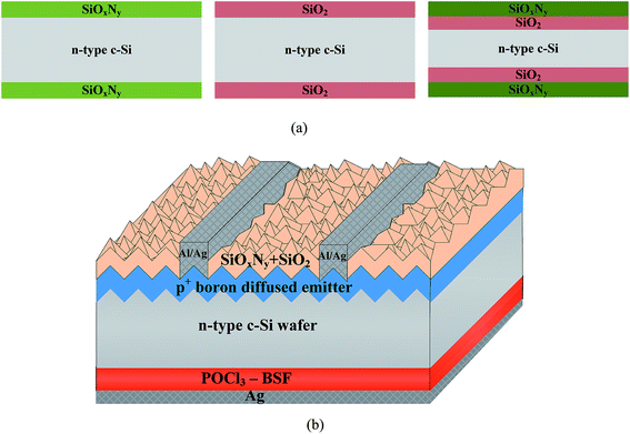 | ||
| Fig. 1 (a) Lifetime test structure used in this study, and (b) schematic diagram of the n-type c-Si solar cell with SiOxNy/SiO2 passivation layers. | ||
2.3 Cell fabrication
Fig. 1b shows the solar cell structure used in this study. Random pyramid texturing was carried out using 2% NaOH for efficient light trapping. Boron diffused p+-emitter was formed with an initial emitter sheet resistance (Rs) of 30 Ω square−1, in a diffusion furnace at 950 °C. Boron-silicate glass (BSG) formed during emitter formation was removed by using 10% HF and 10% HCl for 1 min each. The emitter was etched back using HF![[thin space (1/6-em)]](https://www.rsc.org/images/entities/char_2009.gif) :
:![[thin space (1/6-em)]](https://www.rsc.org/images/entities/char_2009.gif) HNO3
HNO3![[thin space (1/6-em)]](https://www.rsc.org/images/entities/char_2009.gif) :
:![[thin space (1/6-em)]](https://www.rsc.org/images/entities/char_2009.gif) CH3COOH acids to have high Rs of 70–80 Ω square−1. After that, back surface field was formed with a targeted Rs of 50 Ω square−1, obtained by using POCl3 doping in a diffusion furnace at 860 °C. A 80 nm thick SiOxNy with refractive index of 1.57 was deposited over the SiO2 as an anti-reflection coating. Using Ag paste high throughput blanket metal was formed on the back surface for back contact, and for front contact grid (80 μm width) screen-printed Al and Ag paste was used. To improve the contacts, the samples were then cured and co-fired in a conveyer belt furnace.
CH3COOH acids to have high Rs of 70–80 Ω square−1. After that, back surface field was formed with a targeted Rs of 50 Ω square−1, obtained by using POCl3 doping in a diffusion furnace at 860 °C. A 80 nm thick SiOxNy with refractive index of 1.57 was deposited over the SiO2 as an anti-reflection coating. Using Ag paste high throughput blanket metal was formed on the back surface for back contact, and for front contact grid (80 μm width) screen-printed Al and Ag paste was used. To improve the contacts, the samples were then cured and co-fired in a conveyer belt furnace.
Fourier transform infrared (FTIR, model: Shimadzu IR Prestige-21) characterization was used for SiOxNy film composition, and for information about molecular vibration mode and functional groups. The thickness and refractive index were determined using a spectroscopic ellipsometer (model VB250). The reflectance of the samples was measured using an incident photon to current conversion efficiency measurement system. For solar cell spectral response, QEX7 system was used in the wavelength region between 300 nm and 1100 nm. Current–voltage (I–V) measurements under illuminated conditions (AM1.5 G, 100 mW cm−2) were performed by (i) PASAN cell tester (CT801), and (ii) Suns-Voc cell tester (WCT-120 PASAN cell tester CT801).
3. Results and discussion
SiOxNy film properties are reported in terms of lifetime, defect charges in the passivated layer. Chemical characteristics of the SiOxNy films are analyzed from FTIR measurements. The characteristics of an optimized SiOxNy single layer deposited over the thin SiO2 layer are studied in terms of lifetime, finally, fabricated solar cells are characterized by light I–V measurements.3.1 Lifetime and refractive index
The SiOxNy films deposited at different gas flow ratios (R), with SiH4 gas flow kept constant, are plotted against lifetime (τeff) and refractive index (Fig. 2a). The later has been obtained from spectroscopic ellipsometry.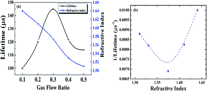 | ||
| Fig. 2 Optimization of SiOxNy film as a function of gas flow ratio. (a) Minority carrier lifetime and refractive index as a function of the gas flow ratio (R = N2O/(N2O + NH3)) with SiH4 flow kept constant, (b) variation of the reciprocal of lifetime with refractive index, data extracted from Fig. 2a. | ||
The refractive index is strongly influenced by the gas flow ratio. With a decrease in the gas flow ratio, refractive index increases from 1.51 to 1.64. This is due to the fact that an increase in the gas flow ratio causes an increase in oxygen content, and hence a decrease in the refractive index.14 For cell fabrication, SiOxNy film with refractive index of 1.57 is used since the corresponding SiOxNy film showed a highest minority carrier lifetime (Fig. 2a) due to effective passivation. The minority carrier lifetime with different gas flow ratio is also shown in Fig. 2a. The SiOxNy film deposited with gas flow ratio of 0.3 is found to have highest minority carrier lifetime of 145 μs.
To study the effect of minority carrier lifetime versus refractive index of SiOxNy film, a graph of the reciprocal of minority carrier lifetime versus refractive index is shown in Fig. 2b. In this regard, Strickler–Berg relation15 is used to validate the relation between these two parameters. As mentioned below, the fluorescence lifetime (in our case lifetime of photogenerated carrier) is inversely proportional to the square of the refractive index:
| 1/τ ∞ n2 | (1) |
When plotted between the inverse of a minority carrier lifetime and refractive index, as shown in Fig. 2b, the curve represents a parabola. It is evident that, as the (1/τ) value decreases, refractive index increases to 1.57, and then continues to increase with (1/τ). The variation in the minority carrier lifetime with refractive index is attributed to the bonding arrangement in the SiOxNy film. For n = 1.57, the nitrogen incorporated in the oxygen network (Fig. 2) effectively saturates the dangling bonds and hence the minimum in (1/τ) value.
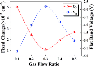
From Fig. 2a, it was also found that SiOxNy film deposited with a gas flow ratio of 0.1 shows relatively lower minority carrier lifetime. This is due to the fact that when the gas flow ratio start increases, interface defect states start decreases (Fig. 3) to a minimum at 0.3 and then it increases with gas flow ratio. Correspondingly, minority carrier lifetime start increases to a maximum at 0.3 and then decreases (Fig. 2a). Highest minority carrier lifetime is due to the low defect states at the interface between SiOxNy/c-Si and hence effective passivation.
3.2 Defect charges in the passivated layer
The interface between SiOxNy and c-Si substrate has been investigated using C–V measurements. The fixed oxide charges (Qf) can be extracted16,17 from the associated flat-band voltage (Vfb) as follows:
 | (2) |
In Fig. 3, Qf and Vfb are plotted as a function of the gas flow ratio (R), when SiH4 gas flow kept constant. A minimum Vfb has been obtained corresponding to the gas flow ratio of 0.3 which indicate the balance of oxygen and nitrogen content in the passivated film. The low density of fixed positive oxide charges in the SiOxNy films prepared for R = 0.3 indicate a high quality interface region. The positive charges in the film can be attributed to the E centers and K centers of Si–O tetrahedra (for SiO2)18 and Si–N bonds (for SiNx)19 respectively. The oxygen-vacancy (O3–Si) defects originated from the E centers are responsible for the fixed positive oxide charges in thermal oxide structures.20 But, in the case of SiOxNy film, this defect site itself may be different as the oxygen binding energy is lower in the oxynitride compared with pure oxide. Nitrogen in the SiOxNy film acts as substitute for oxygen and replaces the weak and strained Si–O bonds by rigid and strong Si–N bonds.21 As a consequence of release in structural strains, defect concentration is reduced in the entire oxide and mechanical stress at the SiOxNy/c-Si interface is decreased. The observed low interface charge density (i.e. fixed oxide charges) can be due to the reasons mentioned above.21
For the gas flow ratio of 0.5, due to the incorporation of oxygen in the film, nitrogen and hydrogen content in the film decreases and there is a tendency to form stoichiometric Si–O bond. In contrast to thermal oxide, the Si–O bonds formed at low temperature do not create a good passivation effect as compared to Si–N or Si–H bonds. This reduced passivation effect can be attributed to the inversion layer created by the fixed charge density in SiOxNy layer with an increase in K+ center (i.e. fixed charges) which is higher as compared to SiOxNy films for the gas flow ratio of 0.3.22 Though the K+ centers improve the surface passivation by minimizing the surface recombination at the interface, it may induce an inversion layer at the p-type surface which leads to passivation degradation.
3.3 FTIR analysis
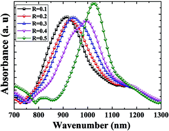
Fig. 4 shows the FTIR spectra of the SiOxNy films deposited for various gas flow ratios while keeping SiH4 flow constant. FTIR analysis provides an understanding of the chemical bonding configurations of the SiOxNy films. Alayo et al.23 reported that the predominant absorption band is localized between 800 cm−1 and 1200 cm−1, and it can be deconvoluted into Si–N and Si–O groups.As the gas flow ratio increases, the absorbance peaks shift towards higher wave numbers (as shown in Fig. 4), which may be attributed to the increase in oxygen concentration with a decrease in refractive index. Observed peak around 950 cm−1 for the gas flow ratio of R = 0.3 can be due to the stretching vibrational mode of Si–N–Si bonds,24 which confirms the nitrogen incorporation in the oxide network. An intense absorption band around 1000 cm−1 for the gas flow ratio of R = 0.4 corresponds to the asymmetric stretching vibration of the oxygen atom.25,26 The SiOxNy film with gas flow ratio of R = 0.5 yielded two separate absorbance peaks; one is the Si–O stretching mode at 1050 cm−1 and the other is the Si–N bending mode at 810 cm−1. Since the oxygen concentration increases as the gas flow ratio increases, for R = 0.5, Si–O stretching mode dominates and suppresses the formation of the Si–N stretching mode. Hence, Si–N bonds are gradually replaced by the Si–O bonds to form SiOxNy films. Wong et al.27 have also shown the absorbance peak shifts towards higher wave numbers, as the electro-negativity of the oxygen substituent exceeds that of nitrogen atom.
3.4 Lifetime variation with different passivation layer
The effects of post-deposition treatments such as forming gas anneal, and fast firing on SiNx/SiO2/c-Si and SiOxNy/SiO2/c-Si stacks are shown in Fig. 5. Thermal SiO2 on c-Si does not provide significant surface passivation as reflected by the lifetime of about 10 μs (not shown in Fig. 5). However, subsequent as-deposited SiOxNy on SiO2/c-Si, and SiNx on SiO2/c-Si showed an improved lifetime of 120 and 90 μs, respectively. After forming gas anneal, effective lifetimes of 512 and 457 μs were achieved for SiOxNy/SiO2/c-Si structure and SiNx/SiO2/c-Si structure, respectively. After fast firing process, the lifetime increases to 690 and 656 μs, and effectively passivates the boron emitter (i.e. higher the lifetime, higher the passivation quality). During the firing process, the permeation of atomic hydrogen into the SiO2/c-Si interface passivate Si dangling bonds at the interface and hence increase in lifetime.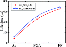 | ||
| Fig. 5 Variation of lifetime with post-deposition treatments on SiNx/SiO2/c-Si stack, and SiOxNy/SiO2/c-Si stack. | ||
3.5 Solar cell parameters with different passivation layer
Fig. 6 shows the internal quantum efficiency (IQE) of two solar cells. One cell was passivated by SiOxNy/SiO2 and other cell was passivated by SiNx/SiO2. IQE measurements were used to understand the contribution of the passivation. An improved passivation is evident from an improved blue response for the SiOxNy/SiO2 passivation stack. The resulted IQE of >90% in the wavelength range between 300 and 550 nm establishes the efficacious passivation of the boron emitter using SiOxNy/SiO2 stack. It can be inferred from Fig. 6 that in the higher wavelength region, hardly any change is observed between two cells due to identical full area BSF at the rear side.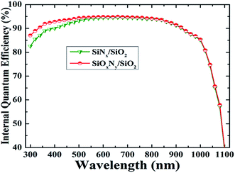 | ||
| Fig. 6 Internal quantum efficiency of the two solar cells; one cell was passivated by SiOxNy/SiO2 stack and another cell was passivated by SiNx/SiO2 stack. | ||
Fig. 7 shows light I–V measurement for two cells, one passivated with SiOxNy/SiO2 stack and another passivated with SiNx/SiO2 stack layers. Two types of measurement systems, viz. PASAN cell tester CT801, and Suns-Voc cell tester WCT-120 were used to characterize soar cells. In the former, measurement includes the effect of series resistance in solar cells, and in the latter, measurement excludes the effect of series resistance. A comparison between the results obtained on solar cell are shown in Fig. 7. The reference cell (SiNx/SiO2 stack) resulted Voc of 618 mV, Jsc of 37.3 mA cm−2, fill factor (FF) of 78.44% and efficiency (η) of 18.01%. The cell with SiOxNy/SiO2 stack passivation layer showed Voc of 626 mV, Jsc of 38.47 mA cm−2, FF of 76.53% and η of 18.58%. As compared to the reference cell, a significant increase in Voc and Jsc of 8 mV and 1.17 mA cm−2 respectively shows the superior characteristics of SiOxNy/SiO2 stack passivation. In the above results, the influence of series resistance in the cell is included.
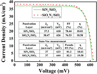 | ||
| Fig. 7 Light I–V curve of two solar cells; one cell was passivated by SiOxNy/SiO2 and another cell was passivated by SiNx/SiO2 stack (in each case, cell area 3.2 × 3.2 cm2). | ||
On the other hand, when the influence of series resistance of the cell is excluded by using Suns Voc measurement system, the following results are obtained. For the reference cell, Voc, Jsc, pseudo FF and η of 623 mV, 37 mA cm−2, 81.2% and 18.61% respectively are obtained. For the cell with SiOxNy/SiO2 stack passivation, Voc, Jsc, pseudo FF and η of 644 mV, 37 mA cm−2, 82.3% and 19.58% respectively are obtained. From Suns Voc results it is clear that with optimized metallization, the cell characteristics will improve further. In addition, an increase in Voc of 21 mV compared to the reference cell shows the superior passivation quality of SiOxNy/SiO2 stack.
4. Conclusions
The passivation properties of SiOxNy/SiO2 stack for boron emitter passivation has been studied based on the carrier lifetime, refractive index, chemical bonding, and the presence of fixed oxide charges with respect to the gas flow ratio. The minority carrier lifetime for the SiOxNy/SiO2 stack over the c-Si resulted in 0.690 ms and the light I–V results for the corresponding cell showed Voc of 644 mV, Jsc of 37 mA cm−2, fill factor of ∼82.3% and efficiency of 19.58%. With further optimization in the front side metallization and rear side passivation, the device characteristics may improve further.Acknowledgements
This work was supported by New and Renewable Energy Technology Development Program of the Korea Institute of Energy Technology Evaluation and Planning (KETEP) grant funded by the Korea government Ministry of Trade, Industry and Energy (Grant No. 20143020010860).References
- N. Balaji, S. Q. Qamar, C. Park, J. Raja, R. Jeyakumar and J. Yi, Transactions on Electrical and Electronic Materials, 2015, 16, 227 CrossRef.
- J. Zhao, Sol. Energy Mater. Sol. Cells, 2004, 82, 53 CrossRef CAS.
- J. Choi, S. Roh, J. Jung and H. Seo, Transactions on Electrical and Electronic Materials, 2013, 14, 203 CrossRef.
- T. Lauinger, J. Schmidt, A. G. Aberle and R. Hezel, Appl. Phys. Lett., 1996, 68, 1232 CrossRef CAS.
- F. H. P. M. Habraken and A. E. T. Kuiper, Mater. Sci. Eng., R, 1994, 12, 123 CrossRef.
- S. Gatz, H. Plagwitz, P. P. Altermatt, B. Terheiden and R. Brendel, Proceedings of the 23rd European Photovoltaic Solar Energy Conference, Valencia, Spain, 2008, p. 1033 Search PubMed.
- B. Hoex, J. Schmidt, R. Bock, P. P. Altermatt, M. C. M. van de Sanden and W. M. M. Kessels, Appl. Phys. Lett., 2007, 91, 112107 CrossRef.
- R. Jeyakumar, A. Verma, B. G. Díaz, R. G. Lemus, C. del Cañizo, E. G. Tabarés, I. R. Stolle, F. Granek, L. Korte, M. Tucci, J. Rath, U. P. Singh, T. Todorov, O. Gunawan, S. Rubio, J. L. Plaza, E. Diéguez, B. Hoffmann, S. Christiansen and G. E. Cirlin, Prog. Mater. Sci., 2016, 82, 294 CrossRef.
- J. Schmidt and K. Bothe, Phys. Rev. B: Condens. Matter Mater. Phys., 2004, 69, 1 Search PubMed.
- D. Macdonald and L. J. Geerligs, Appl. Phys. Lett., 2004, 85, 4061 CrossRef CAS.
- P. P. Altermatt, H. Plagwitz, R. Bock, J. Schmidt, R. Brendel, M. J. Kerr and A. Cuevas, Proceedings of the 21rd European Photovoltaic Solar Energy Conference, Germany, 2006, p. 647 Search PubMed.
- J. Benick, A. Richter, M. Hermle and S. W. Glunz, Phys. Status Solidi RRL, 2009, 3, 233 CrossRef CAS.
- J. Dupuis, E. Fourmond, J. F. Lelièvre, D. Ballutaud and M. Lemiti, Thin Solid Films, 2008, 516, 6954 CrossRef CAS.
- K. E. Mattsson, J. Appl. Phys., 1995, 77, 6616 CrossRef CAS.
- C. Jones and K. Suhlin, J. Phys.: Conf. Ser., 2006, 45, 223 CrossRef CAS.
- J. F. Lelièvre, E. Fourmond, A. Kaminski, O. Palais, D. Ballutaud and M. Lemiti, Sol. Energy Mater. Sol. Cells, 2009, 93, 1281 CrossRef.
- S. Chatterjee, S. K. Samanta and C. K. Maiti, J. Phys. D: Appl. Phys., 2003, 36, 901 CrossRef CAS.
- K. Vanheusden and A. Stesmans, Appl. Phys. Lett., 1993, 62, 2405 CrossRef CAS.
- P. M. Lenahan and S. E. Curry, Appl. Phys. Lett., 1990, 56, 157 CrossRef CAS.
- S. K. Samanta, S. Chatterjee, S. Maikap, L. K. Bera, H. D. Banerjee and C. K. Maiti, J. Appl. Phys., 2003, 93, 2464 CrossRef CAS.
- H. C. Lu, E. P. Gusev, T. Gustafsson, E. Garfunkel, M. L. Green, D. Brasen and L. C. Feldman, Appl. Phys. Lett., 1996, 69, 2713 CrossRef.
- A. G. Aberle, Sol. Energy Mater. Sol. Cells, 2001, 65, 239 CrossRef CAS.
- M. Alayo, I. Pereyra, W. Scopel and M. C. Fantini, Thin Solid Films, 2002, 402, 154 CrossRef CAS.
- M. K. Gunde and M. Macek, Phys. Status Solidi A, 2001, 183, 439 CrossRef.
- D. V. Tsu, G. Lucovsky and B. N. Davidson, Phys. Rev. B: Condens. Matter Mater. Phys., 1989, 40, 1795 CrossRef CAS.
- M. Zacharias, D. Dlmova-Malinovska and M. Stutzmann, Philos. Mag. B, 1996, 73, 799 CrossRef CAS.
- C. K. Wong, H. Wong, C. W. Kok and M. Chan, J. Cryst. Growth, 2006, 288, 171 CrossRef CAS.
Footnote |
| † These authors equally contributed. |
| This journal is © The Royal Society of Chemistry 2016 |

