Bio-templated germanium photonic crystals by a facile liquid phase deposition process†
Wu Yi,
Ding-Bang Xiong*,
Wang Zhang,
Huilan Su,
Qinglei Liu,
Jiajun Gu,
Shenmin Zhu and
Di Zhang
State Key Laboratory of Metal Matrix Composites, Shanghai Jiao Tong University, Shanghai, 200240, China. E-mail: xiongdingbang@sjtu.edu.cn
First published on 29th July 2016
Abstract
Ge photonic crystals were synthesized by replicating butterfly wings with GeO2 via a facile liquid phase deposition followed by a reducing process. The reflectance spectra of the Ge photonic crystals show a broad peak at wavelengths of 700–800 nm and angle-dependent peak positions.
A photonic crystal (PC) is composed of periodically repeating regions of high and low refractive index, which can be used for controlling light propagation by defining a photonic stop band. Some top-down methods, such as photoetching, chemical or electrochemical etching of corresponding dense materials,1,2 are widely used to fabricate PCs because they can precisely control composition and crystallinity, but these top-down methods are limited by the structural diversity and size of PCs, and some expensive instruments are also needed. On the other hand, bottom-up approaches can enrich PC structure through template assisted synthesis or assembly of building block units. A typical procedure for template assisted synthesis3 includes three steps including preparing template, infiltrating template with objective materials, and removing template. While various routes have been applied for infiltrating template, including chemical vapour deposition, electrodeposition, atomic layer deposition etc.,4–7 the types of templates are highly restricted by assembling and synthesis technologies. For example, opal or inverse opal is one of the few artificial photonic crystal structures that can be fabricated by assembly of building block units or template assisted synthesis.
Fortunately, through millions of years of evolution, nature provides us a variety of 1D, 2D and 3D PCs, which can be used as template to obtain artificial PCs. For example, wings of butterfly and moth that almost have 175![[thin space (1/6-em)]](https://www.rsc.org/images/entities/char_2009.gif) 000 species to choose from are very important natural PCs, which could be transferred into a wealth of artificial PCs by template assisted synthesis and inspire the design of PCs. Even though the kaleidoscopic microstructures in wings, thanks to the similarity in constituents (such as polysaccharide chitin), once a fabrication route has been established, a diversity of functional materials with various PC structures could be obtained via the same process.
000 species to choose from are very important natural PCs, which could be transferred into a wealth of artificial PCs by template assisted synthesis and inspire the design of PCs. Even though the kaleidoscopic microstructures in wings, thanks to the similarity in constituents (such as polysaccharide chitin), once a fabrication route has been established, a diversity of functional materials with various PC structures could be obtained via the same process.
In addition to the periodic structures, refractive index contrast is another important factor determining photonic stop band gap, and the materials with high refractive index values are usually desired for producing PCs with large photonic stop band gap.8–11 Among conventional semiconductors, Ge almost has the highest refractive index (5.748 at 590.38 nm), indicating that larger photonic stop band gap could be obtained in Ge PCs. Many efforts have been made to synthesize various replicas of natural photonic crystals with oxide semiconductors (SnO2, CdS, TiO2, and Fe3O4 etc.) and elemental metals (like Au, Ag and Cu etc.).12–18 However, to the best of our knowledge, replicating wings with high refractive index semiconductors such as Ge are still largely unexplored, mainly because moisture-sensitive germanium alkoxides or germanium chlorides were usually needed as germanium source, making synthesis conditions very harsh.19,20 Herein, Ge photonic crystals templated from natural butterfly wings were fabricated by an improved facile liquid deposition process21 without any atmosphere protection, showing intact, three-dimensional shapes with submicrometre resolution inherited from the butterfly wings, and their photonic crystal properties were characterized and discussed.
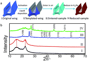
Typically, the bio-template liquid phase deposition process includes four steps (Fig. 1a): activation, liquid deposition, sintering and reduction. At first, the original butterfly wings of Euploea mulciber were placed in 6% HCl (AR) aqueous solution for 4 h to remove some inorganic substances, and then activated by 8% NaOH (AR) aqueous solution at 50 °C for 4 h. Secondly, 25 mL deionized water was mixed with 0.75 mL 25% aqueous ammonia (AR) in a beaker followed by adding 0.75 g GeO2 (5 N) powder. While stirring at 50–70 °C for 20 min, the white solution turned to be transparent. After adjusting the pH with phosphoric acid to 5.0–5.2, activated butterfly wings were immersed in the solution at 35 °C for 8 h (denoted as templated-wing hereafter). After then, the specimen was heated at 500 °C in air for 2 h (denoted as sintered-sample hereafter) to remove the original template. At last, the sintered-samples were reduced at 500 °C for 3 h under 1![[thin space (1/6-em)]](https://www.rsc.org/images/entities/char_2009.gif) :
:![[thin space (1/6-em)]](https://www.rsc.org/images/entities/char_2009.gif) 4 mixed H2/Ar atmosphere to obtain Ge replicas (denoted as reduced-sample hereafter).
4 mixed H2/Ar atmosphere to obtain Ge replicas (denoted as reduced-sample hereafter).
Original butterfly wings are mainly made up of chitins, deacetylation with NaOH could expose more activated groups like amidogen and hydroxy on the surface to absorb and chelate metallic ions.22,23 And the dissolution of GeO2 in NH3·H2O to generate Ge5O112− is reversible:21
Thus, as pH is below 7.0, Ge5O112− would reverse to generate GeO2 and give priority to nucleate on the surface of wings because of the activated groups. To obtain a dense and homogeneous nano-coating, four factors were investigated in this process, including solid content of GeO2 dissolved in the solution, acid type used to adjust pH, pH and duration of immersing the butterfly wings in the solution (ESI, Fig. S1 and S2 and Tables S1 and S2†). The condition was optimized to a solid content of GeO2 being 3%, a pH of ∼5 adjusted by phosphoric acid solution, and immersing butterfly wing in the solution for about 8 h. While low solid content would result in the formation of gel, micro-meter crystals appeared as solid content reached 5%. Phosphoric acid was chosen to control the rate of the reverse reaction of Ge5O112− because of its appropriate acid strength and ionization rate. With increasing the duration from 8 h to 10 h and a slight decrease of pH from 5.2 to 4.8 would both lead to the formation of micro-meters particles.
As shown in Fig. 1b, the original (I) and templated-wing (II) have the same powder X-ray diffraction (XRD) pattern with two broad peaks identified to chitin. It reveals that no crystalline phase was formed after being immersed in the solution for 8 h. The sintered-sample (III) was identified as a hexagonal GeO2 (S.G. P3321, PDF#36-1463), and could be further thoroughly reduced to a cubic Ge (S.G. Fd![[3 with combining macron]](https://www.rsc.org/images/entities/char_0033_0304.gif) m, PDF#04-0545), as indicated by the XRD pattern of the reduced-sample (IV) in which no diffraction peak of GeO2 could be detected.
m, PDF#04-0545), as indicated by the XRD pattern of the reduced-sample (IV) in which no diffraction peak of GeO2 could be detected.
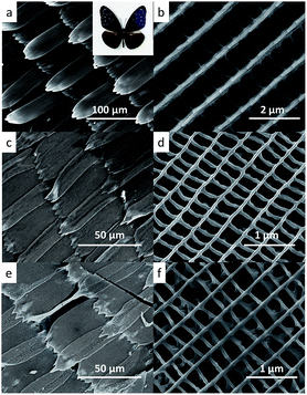
Fig. 2 displays the scanning electron microscope (SEM) images of original and replicated wings at both high and low magnifications. In the present work, bluish purple fore wings of Euploea mulciber (the insert in Fig. 2a) was chosen as the representative, and their morphologies were shown in Fig. 2a and b. The wings are covered by many scales with a length of about 150 μm and a width of about 50 μm. Each scale has an ordered three-dimensional structure with submicrometre resolution with ridges running along the scale, and the ridges are further interconnected by short ribs forming rectangular windows in between (Fig. 2b). While the arrangement and shape of scales in the original wings was kept in both the sintered-sample (Fig. 2c and d) and reduced-sample (Fig. 2e and f), the width of the replicated scales shows more than 50% shrink during the process obvious, from about 50 μm in the original wings to about 20 μm in both replicas, which might be caused by a low deposition yield. Meanwhile extending time and lowering pH failed to approve it because of the formation of micro-meters particles. The three-dimensional structure of the scales, parallel ridges interconnected by ribs, was also successfully replicated in both replicas, but the distance between two ridges decreased to 300–400 nm in the replicas from about 700 nm in the original wings, which implies a large shrink of more than 50% and is consistent with shape shrink of scales, indicating a uniform replication. In contrast to the sintering process, no obvious shrink occurred during the reducing process, as shown in Fig. 2d and f.
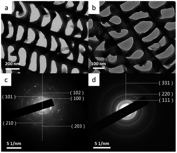
The sintered-sample and reduced-sample were also studied by using transmission electron microscope (TEM). As shown in Fig. 3, the windows structure, with ridges running parallel and the cross ribs joining them, were maintained in both the sintered-sample (Fig. 3a) and reduced-sample (Fig. 3b), and the distance between ridges is measured to be about 300–400 nm, consistent with the results of SEM. The replicated phases were also confirmed by selected area electron diffraction (SAED) (Fig. 3c), consistent with the result of powder XRD. Coming out from the center, the SAED pattern of the sintered-sample can be indexed to the (100), (101), (102), (210) and (203) planes of a hexagonal GeO2 (S.G. P3321), while that of the reduced sample to the (111), (220) and (331) planes of a cubic Ge (S.G. Fd![[3 with combining macron]](https://www.rsc.org/images/entities/char_0033_0304.gif) m). According to above characterizations and analysis, it is reasonable to conclude that a period Ge windows structure has been fabricated successfully by using butterfly wings as the template via a facile liquid phase deposition method.
m). According to above characterizations and analysis, it is reasonable to conclude that a period Ge windows structure has been fabricated successfully by using butterfly wings as the template via a facile liquid phase deposition method.
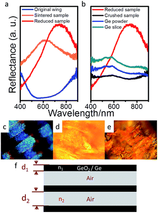
The reflectance spectra of original wings, sintered-sample and reduced-sample were given in Fig. 4a. The reflectance peak of original wing is located at about 397 nm (ref. 24) (out of the detect limit of the spectrograph used), but red shift to 600–650 nm after replicating the butterfly wing with GeO2. Such red shift can also be seen in the reflection spectra of the reduced sample, up to an averaged peak of 780 nm (ESI, Fig. S3†). The corresponding photographs of original wings (obtained by charge-coupled device), sintered-sample and reduced-sample were shown in Fig. 4c–e. The original wing shows bluish purple, the sintered sample shows yellow and the reduced sample displays red, identical to the spectra as shown in Fig. 4a. To confirm the effect from photonic crystal structure, the reflected spectra of germanium with different structures including the reduced-sample, crushed reduced-sample (grinded the reduced-sample in an agate mortar to completely destroy the replicated butterfly wing structure), Ge powder and Ge slices were analysed (Fig. 4b, ESI, S4†). It is clearly seen that, while the reduced-sample shows a strong and broad peak, the crushed sample, Ge powder (purchased from Sinopharm Chemical Reagent Co., Ltd.) and Ge slices (purchased from Aladdin Industrial Corporation) display some weak peaks between 500 nm and 600 nm, which may be attributed to the photoluminescence of Ge and GeO2 generated on the surface.25,26
The exact reflection peaks of natural wings of photonic structures are still hard to estimate, but can be simplified to be a periodically repeating regions of high and low refractive index (Fig. 4f), and thus the reflective peak of the natural wings can be estimated by λ = 2(n1d1 + n2d2),15,27 where λ is the wavelength of peak reflection for a perfect multi-layered photonic structure, n1 and n2 are the refractive indexes of the first and second layer (they are chitins with n1 = 1.54 and air with n2 = 1 in butterfly wings), and d1 and d2 are the corresponding layer thickness. Thus, as shown in Fig. 2b, the distance between two ridges in original wings is about 700 nm, and the width of the ridge is 250 nm, which means, according to the simplified model, the reflectance peak may locate at infrared ray (IR) range. The reflectance peak located at about 397 nm is reported to be mainly attributed to the microstructure of the ridges.24 But in the sintered-sample and reduced-sample, because of contraction, the distance between ridges has shrunk to about 350 nm shown in Fig. 2d and f. Therefore, the reflective peak generated by the period structure of ridges shifts to visible region as shown in the Fig. 4a. We herein apply the peak shift to trace the structure-related peak from sintered-sample to reduced sample. In this model, the transformation of photonic structures from sintered-sample (GeO2) to reduced sample (Ge) can be divided into two separate parts for convenient estimation: (I) ingredients replacement and (II) dimensional shrinkage. In part (I), GeO2 (n1 = 1.60 when λ = 700 nm) in sintered-sample was replaced by Ge (n1 = 5.02 when λ = 700 nm) in reduced-sample. In part (II), the distance between two ridges (d2) lies between 300 nm and 400 nm (according to SEM results) in both sintered-sample and reduced sample, and we fix it to 350 nm on average in both samples for simplicity, i.e., d2 = 350 nm. But according to TEM results, the width of ridges (d1) shrank from about 105 nm in the sintered-sample to 80 nm in the reduced-sample on average. Thus, according to this simple model, the change in both ingredient and size would induce a peak red shift of 230 nm. Compared to the measured value (∼160 nm), the estimated larger value (230 nm) could be caused by the simplified treatment of the complex natural photonic structures and the measurement errors in both samples.
Like other PCs, the as-prepared reduced sample displays angle-dependent (relative to perpendicular) optical properties. As shown in Fig. 5, the non-PC Ge slice shows angle-independent optical properties, but an obvious red shift occurs on the reduced-sample with increasing of the angle, which can be simply explained by Bragg's law, 2d![[thin space (1/6-em)]](https://www.rsc.org/images/entities/char_2009.gif) sin
sin![[thin space (1/6-em)]](https://www.rsc.org/images/entities/char_2009.gif) θ = nλ (λ is the wavelength, θ is the scattering angle, n is integer representing the order of the diffraction peak, and d is the interplanar distance). With the increase of the incidence angles, and the incidence light with longer wavelength can satisfy the Bragg condition and is reflected, which leads to substantial shift in reflection spectrum.
θ = nλ (λ is the wavelength, θ is the scattering angle, n is integer representing the order of the diffraction peak, and d is the interplanar distance). With the increase of the incidence angles, and the incidence light with longer wavelength can satisfy the Bragg condition and is reflected, which leads to substantial shift in reflection spectrum.
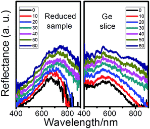 | ||
| Fig. 5 The reflection spectra of the reduced-sample (left) and Ge slice (right) at different angles relative to normal direction. | ||
In conclusion, we succeeded in replicating the microstructure of butterfly wings scales with Ge by using a facile liquid phase deposition. The as-prepared reduced-sample shows a broad peak located at 700–800 nm and displays angle-dependent optical properties, which is demonstrated to be derived from the period windows photonic structure. Our results provide a well-suited technique to make photonic crystals with a high refractive index, via which kaleidoscopic natural photonic structures with similar constituents (polysaccharide chitin) could be replicated.
Acknowledgements
This work was supported by the National Natural Science Foundation of China (Grant No. 51371115, 51572169, 51271116), the National Basic Research Program of China (973 Program, No. 2011CB922200), Shanghai Science & Technology Committee (No. 14JC1403300, 14520710100).Notes and references
- K. Hennessy, A. Badolato, A. Tamboli, P. M. Petroff, E. Hu and J. Dreiser, Appl. Phys. Lett., 2005, 87, 021108 CrossRef.
- E. V. Astrova, G. V. Fedulova and E. V. Guschina, Semiconductors, 2010, 44, 1617–1623 CrossRef CAS.
- P. V. Braun, Chem. Mater., 2014, 26, 277–286 CrossRef CAS.
- T. Song, Y. Jeon, M. Samal, H. Han, H. Park, J. Ha, D. K. Yi, J.-M. Choi, H. Chang, Y.-M. Choi and U. Paik, Energy Environ. Sci., 2012, 5, 9028–9033 CAS.
- R. G. Shimmin, R. Vajtai, R. W. Siegel and P. V. Braun, Chem. Mater., 2007, 19, 2102–2107 CrossRef CAS.
- X. Liu, J. Zhao, J. Hao, B.-L. Su and Y. Li, J. Mater. Chem. A, 2013, 1, 15076–15081 CAS.
- X. Meng, R. Al-Salman, J. Zhao, N. Borissenko, Y. Li and F. Endres, Angew. Chem., Int. Ed., 2009, 48, 2703–2707 CrossRef CAS PubMed.
- H. Míguez, E. Chomski, F. García-Santamaría, S. J. Marta Ibisate, C. López, F. Meseguer, J. P. Mondia, G. A. Ozin, O. Toader and H. M. v. Driel, Adv. Mater., 2001, 13, 1634–1637 CrossRef.
- A. Blanco, E. Chomski, S. Grabtchak, M. Ibisate, S. John, S. W. Leonard, C. Lopez, F. Meseguer, H. Miguez and J. Mondia, Nature, 2000, 405, 437–440 CrossRef CAS PubMed.
- F. García-Santamaría, M. Xu, V. Lousse, S. Fan, P. V. Braun and J. A. Lewis, Adv. Mater., 2007, 19, 1567–1570 CrossRef.
- A. Sharma and M. Kumar, IET Optoelectron., 2015, 9, 24–28 CrossRef.
- Y. Wang, D. B. Xiong, W. Zhang, H. Su, Q. Liu, J. Gu, S. Zhu and D. Zhang, Catal. Today, 2016, 274, 15–21 CrossRef CAS.
- J. Gu, W. Zhang, H. Su, T. Fan, S. Zhu, Q. Liu and D. Zhang, Adv. Mater., 2015, 27, 464–478 CrossRef CAS PubMed.
- F. Song, H. Su, J. Chen, W.-J. Moon, W. M. Lau and D. Zhang, J. Mater. Chem., 2012, 22, 1121–1126 RSC.
- J. Han, H. Su, F. Song, D. Zhang and Z. Chen, Nanoscale, 2010, 2, 2203–2208 RSC.
- W. Zhang, D. Zhang, T. Fan, J. Gu, J. Ding, H. Wang, Q. Guo and H. Ogawa, Chem. Mater., 2009, 21, 33–40 CrossRef.
- W. Peng, S. Zhu, W. Wang, W. Zhang, J. Gu, X. Hu, D. Zhang and Z. Chen, Adv. Funct. Mater., 2012, 22, 2072–2080 CrossRef CAS.
- Y. Tan, J. Gu, X. Zang, W. Xu, K. Shi, L. Xu and D. Zhang, Angew. Chem., Int. Ed., 2011, 50, 8307–8311 CrossRef CAS PubMed.
- R. Al-Salman, J. Mallet, M. Molinari, P. Fricoteaux, F. Martineau, M. Troyon, S. Z. E. Abedinw and F. Endres, Phys. Chem. Chem. Phys., 2008, 10, 6233–6237 RSC.
- K. Okumura, K. Asakura and Y. Iwasawa, Langmuir, 1998, 14, 3607–3613 CrossRef CAS.
- C. Jing, J. Hou and Y. Zhang, J. Am. Ceram. Soc., 2007, 90, 3646–3650 CrossRef CAS.
- K. Ravi and N. V. Majeti, React. Funct. Polym., 2000, 46, 1–27 CrossRef.
- W. Zhang, D. Zhang, T. Fan, J. Ding, Q. Guo and H. Ogawa, Microporous Mesoporous Mater., 2006, 92, 227–233 CrossRef.
- F. Song, H. Su, J. Chen, D. Zhang and W.-J. Moon, Appl. Phys. Lett., 2011, 99, 163705 CrossRef.
- R. Chivas, S. Yerci, R. Li, L. Dal Negro and T. F. Morse, Opt. Mater., 2011, 33, 1829–1832 CrossRef CAS.
- X. Meng, J. Zhao, H. Li, F. Endres and Y. Li, Opt. Express, 2012, 20, 9421–9430 CrossRef CAS PubMed.
- S. Kinoshita and S. Yoshioka, ChemPhysChem, 2005, 6, 1442–1459 CrossRef CAS PubMed.
Footnote |
| † Electronic supplementary information (ESI) available: Experiments, materials characterization and repetitive experimental details of reflectance spectra. See DOI: 10.1039/c6ra16139a |
| This journal is © The Royal Society of Chemistry 2016 |

