 Open Access Article
Hydraulic fracturing in methane-hydrate-bearing sand
Yoshihiro
Konno
*a,
Yusuke
Jin
a,
Jun
Yoneda
b,
Takashi
Uchiumi
a,
Kazunori
Shinjou
a and
Jiro
Nagao
*a
aMethane Hydrate Production Technology Research Group, Research Institute of Energy Frontier (RIEF), Department of Energy and Environment, National Institute of Advanced Industrial Science and Technology (AIST), 2-17-2-1 Tsukisamu-Higashi, Toyohira-ku, Sapporo 062-8517, Japan. E-mail: yoshihiro-konno@aist.go.jp; jiro.nagao@aist.go.jp
bMethane Hydrate Geo-mechanics Research Group, RIEF, Department of Energy and Environment, AIST, 16-1 Onogawa, Tsukuba, Ibaraki 305-8569, Japan
First published on 27th July 2016
Abstract
Knowledge of the fracturing behaviors in gas-hydrate-bearing sediments is essential to understand the accumulation mechanism of gas hydrates in fractured sediments and to apply hydraulic fracturing as a well stimulation method when considering gas recovery from gas hydrate reservoirs. We present an experimental study of hydraulic fracturing involving methane-hydrate-bearing sand formed in a triaxial pressure cell. The injection pressure rapidly increased after the start of distilled water injection from the core top through a small port, but suddenly decreased afterward. X-ray computed tomography revealed that laminar fractures, which were oriented in a plane perpendicular to the minimum principal stress, were generated after this pressure drop. The fracturing pressure was 2.9–3.9 MPa above the minimum principal stress. Although the host sediment was unconsolidated, the observed fracture behavior yielded a consolidated-rock-like fracturing mode, i.e., the tensile failure mode. It was affected by the low-permeable feature of hydrate-bearing sediments. The permeability was increased after fracturing and was maintained even after re-confining and closing the fractures. The results indicate that hydraulic fracturing is a promising well stimulation method for low-permeable gas hydrate reservoirs.
1. Introduction
Gas hydrates are crystalline solids composed of water and gas.1 Methane hydrate, which is commonly found in nature, exists in permafrost regions and deep oceanic environments. The global resource of methane in the gas hydrate is estimated as trillions of cubic feet of gas.2 From this perspective, methane hydrate is considered to dominate an important part of the global carbon cycle3 and has potential to become a future energy resource.4To understand the role of methane hydrate on the global carbon cycle, it is important to investigate methane leakage and methane hydrate accumulation processes occurring at/below the sea floor. Methane leakage at the sea floor is recognized as methane inputs into the atmosphere.5 In addition, methane hydrate accumulated below the sea floor is considered to relate to this leakage.6 In many cases, the fracture system allows for gas migration into the hydrate stability zone and affects methane hydrate accumulation.7 Therefore, understanding the fracturing behavior in the hydrate stability zone is quite important. Fracturing and hydrate accumulation are considered a dynamic process on time scales of years to decades.7 To understand the dynamic interaction among gas flow and hydrate formation/dissociation in the fracture system, experimental and numerical studies have been conducted. Fauria and Rempel experimentally studied the fracturing mechanism induced by gas invasion into hydrate-free sandy sediment.8 Jin et al. used a numerical approach to investigate the crack extension induced by hydrate dissociation in low-permeable muddy sediments.9 Fracturing behavior in hydrate-bearing sandy sediments is also essential to understand the process; however, no such study has been reported so far.
From the viewpoint of resource development, fracturing behavior in hydrate-bearing sandy sediments is an important topic for developing a well stimulation method. Depressurization is considered a promising method of gas production from gas hydrate reservoirs. The key factors of depressurization-induced gas production are the initial effective permeability and the initial reservoir temperature, which affect the speed of pressure propagation in reservoirs and the recovery factor of gas, respectively.10 Similar to the case of exploitation of unconventional hydrocarbons, such as shale gas, low production rate and low recovery factor are essential problems to address in realizing commercial gas production from gas hydrate reservoirs. In this respect, enhancing the recovery to assist depressurization is important. Thus far, a number of heat supply methods to enhance the recovery factor have been proposed for relatively low-temperature reservoirs.11–17 In contrast, a well stimulation method for increasing the effective permeability is rarely studied. For low-permeability reservoirs, such as shale, hydraulic fracturing has been applied to create cracks in which hydrocarbons can flow easily. Hydraulic fracturing is potentially effective in gas hydrate reservoirs as a well stimulation method. Ito et al. conducted a laboratory study of hydraulic fracturing in unconsolidated hydrate-free sand and mud layers mimicking the host sediment of methane hydrate reservoirs.18 They found that the fluid injection induced a fracture-like structure at the interface between the hydrate-free sand and the mud layers.18 If fractures can be formed in the gas-hydrate-bearing sediments, then they would accelerate pressure propagation and enlarge the hydrate dissociation area, thereby increasing the gas production rate and the present value of the reservoir. However, to the best of our knowledge, no study has been conducted on hydraulic fracturing in gas-hydrate-bearing sediments, either experimentally or numerically.
To examine hydraulic fracturing in gas hydrate reservoirs, the unique permeability feature of gas-hydrate-bearing sediments should be considered. In gas-hydrate-bearing sediments, the effective permeability of water or gas, which reflects the ability of water or gas to flow when other fluids and hydrate coexist, is relatively low. In contrast, the host sediment frequently exhibits high absolute permeability due to unconsolidated, high-porosity, and coarse-grained sand. For example, in the eastern Nankai Trough, the effective water permeability of hydrate-bearing sediments was 1–100 millidarcies (mD); however, the absolute permeability of host sand sediments was up to 1.5 darcy (D).19 If hydraulic fracturing can be applied to these sediments, the host sand would become a natural proppant and hold the fractures open during gas production. In a modeling study for sand production in gas-hydrate-bearing sediments, sand grains were assumed to be detached from the intact soil skeleton when the hydraulic gradient of the fluid (water or gas) exceeded its critical value.20 Thus, this mechanism is expected to occur during hydraulic fracturing and production processes. It indicates that injection fluid does not necessarily contain proppants for hydraulic fracturing in gas hydrate reservoirs. However, hydrate particle cohesion and reformation after hydraulic fracturing should be considered to ensure the fractures remain open. Hydrate-bearing sandy sediment is consolidated before production because the gas hydrate bonds the sand grains to each other. Injected fluid will drag the bonded gas hydrate away from the sand grains or form cracks in the hydrate particles themselves. However, the gas hydrate can bond again because of cohesion and reformation when the pressure and temperature condition remains within the range of thermodynamic hydrate-stable conditions. This process, which is a time-dependent phenomenon, may close the fractures.
In this study, we present the first laboratory experiment of hydraulic fracturing conducted for methane-hydrate-bearing sand formed in a triaxial pressure cell. Distilled water was injected through a small port into the core to induce fractures in artificial methane-hydrate-bearing sand. The structure inside the core was observed using an X-ray CT scanner to detect the formed fractures. The hydraulic fracturing pressure was investigated for the presence of methane-hydrate-bearing sand. To investigate the requirement of proppants and the probability of restoration of fractures, the permeability was analyzed before fracturing, after forming fractures, and after the closing of fractures by re-confining the core.
2. Experimental
2.1 Apparatus
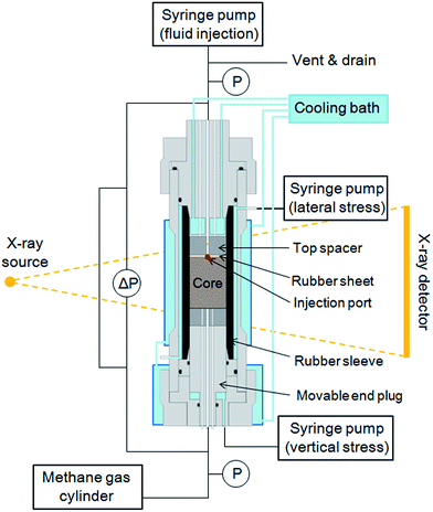
A schematic of the experimental apparatus is shown in Fig. 1. The cylindrical core is 50 mm in diameter and 69.9 mm long, and it is placed inside a triaxial pressure cell. The body of the cell is made of an aluminum alloy to allow for X-ray transmission. The maximum operation pressure of the cell is 10 MPa. An end plug attached to the bottom of the core is movable to enable application of the axial pressure. The surrounding of the core is covered by a rubber sleeve to apply the lateral confining pressure. The axial and lateral confining pressures are independently controlled by separate syringe pumps (Teledyne Isco, 500D). A spacer with an injection port of diameter 3 mm is located at the top of the core. To prevent the leakage of the fracturing fluid through the attachment between the core and the spacer, a rubber sheet is sandwiched between them. The fracturing fluid is injected via a syringe pump (Teledyne Isco, 500D), which controls the injection rate and pressure. A coolant is circulated around the triaxial pressure cell to maintain the system temperature to be within the range of thermodynamic hydrate-stable conditions. A X-ray CT scanner (Hitachi Medico Technology, MCT-130 CBHS)21 is used to observe the structure inside the core. The image resolution is 0.254 mm (vertical) × 0.241 mm (horizontal) per pixel, and the slice pitch is 0.25 mm. The X-ray source and the flat-panel detector move around the sample stage on which the triaxial pressure cell is set.2.2 Sample preparation
Wet Toyoura sand was tapped inside the rubber sleeve to produce the core sample. The porosity derived by the mass balance was 38%. After producing the core sample, the axial and lateral confining pressures were applied at 2.1 MPa and 1.1 MPa, respectively. The partial water saturation method22 was applied to form methane hydrate inside the pores. While maintaining the effective stress, methane gas (purity 99.99%) was gradually pressurized up to 4.1 MPa and the temperature was decreased to approximately 276 K to form methane hydrate inside the pore spaces. After forming methane hydrate, distilled water was injected from the bottom of the core to remove as much of the residual methane gas as possible. The phase saturation derived by the mass balance was 72% of hydrate and 28% of water. After flushing with distilled water, the residual gas was negligible in this experiment. The pore pressure, the axial confining pressure, and the lateral confining pressure were 4.1 MPa, 6.1 MPa, and 5.1 MPa, respectively. The temperature was approximately 276 K, which was within the range of thermodynamic hydrate-stable conditions.3. Results & discussion
3.1 Fracturing behavior
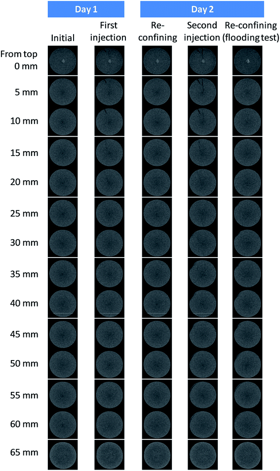
Fig. 2 shows the changes in the injection rate, the injection pressure, the core bottom pressure, and the axial and lateral confining pressures during hydraulic fracturing. The injection rate of fracturing fluid was set at 5 mL min−1, which was sufficient to increase the injection pressure in excess of the fluid penetration into the core. From the safety limitation of the triaxial pressure cell, the maximum injection pressure and fracturing fluid volume were controlled up to 9.0 MPa and 10 mL, respectively. The axial and lateral confining pressures were maintained constant during injection. Fracturing fluid was injected two times for the same core. In the first injection, the injection pressure reached 9.0 MPa and the injection rate drastically decreased from 5 mL min−1 to approximately 0.5 mL min−1. However, a few minutes later, the injection rate gradually increased and reached 5 mL min−1 before stopping the injection. The injection pressure was maintained at 9.0 MPa during the first injection. The X-ray CT image shown in Fig. 3 indicates that a small fracture originated at the injection port was formed (0–20 mm from the core top). After the first injection, the pore pressure was decreased to the initial condition and the core was in the re-confining state. The X-ray CT image obtained approximately one day after re-confining shows that the fracture was closed.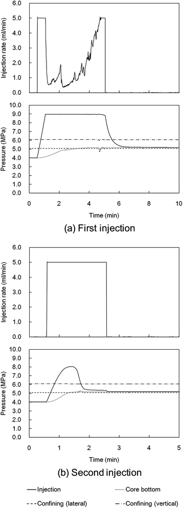 | ||
| Fig. 2 Changes in the injection pressure, the injection rate, the core bottom pressure, and the axial and lateral confining pressures during hydraulic fracturing. | ||
The second injection was conducted approximately one day after the first injection. The injection pressure increased over 8.0 MPa and then decreased sharply toward the lateral confining pressure of 5.1 MPa. The injection rate during the second injection was constant at 5 mL min−1. The X-ray CT image indicates that the small fracture formed during the first injection was opened again, but the fracture was widened (0–20 mm from the core top) and enlarged toward the bottom of the core (25–60 mm from the core top) compared with the fracture caused by the first injection. A few connected fractures were developed in the core in a plane perpendicular to the minimum principal stress, i.e., the lateral confining stress in this experiment. The fractures were straight, laminar, and less tortuous and formed radially.
3.2 Relationship between the fracturing pressure and the strength of hydrate-bearing sand
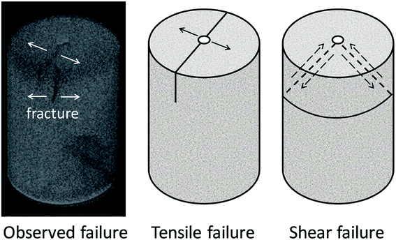
Fig. 4 shows the observed and typical failure modes in this experiment. Shear failure is a sliding mode caused by shear stress inside the core, while tensile failure is an opening mode caused when the fluid pressure overcomes the effective stress and tensile stress of the sediment. The configuration of fractures in our experiment indicates that tensile failure occurred. Therefore, the excess fracturing pressure of 2.9–3.9 MPa (fracturing pressure ranging from 8.0 MPa to 9.0 MPa – minimum principle stress of 5.1 MPa) is related to the tensile strength of hydrate-bearing sand.The tensile strength of hydrate-bearing sand has not been reported previously; however, for bulk hydrates, the tensile strength was investigated experimentally and numerically. Jung and Santamarina experimentally investigated the tensile strength of hydrate mass itself and the hydrate-mineral adhesive strength at zero effective stress condition.23 They reported that the tensile strength of methane hydrate is 0.20 ± 0.03 MPa, which is smaller than the hydrate-calcite adhesive strength.23 Li et al. experimentally investigated the tensile strength of methane hydrate films on gas bubbles by simulating rising gas bubbles in deep water and observed that the tensile strength of the hydrate film increases monotonously from sub-MPa to the order of a few MPa with subcooling.24 They concluded that smaller hydrate crystals formed at higher subcooling consolidated more tightly to form the hydrate film.24 Recently, the strength of polycrystalline methane hydrate was calculated using molecular dynamics (MD) simulations by Wu et al.25 They found that the tensile and compressive stresses of polycrystalline methane hydrate depend on the grain size of the crystals.25 The tensile strength estimated by MD was found to reach ultimate values of ∼0.185 GPa.25 It was one-thousand-fold higher than the experimental data reported by Jung and Santamarina.23
These studies indicate that the tensile strength of gas hydrates strongly depends on the crystalline structure (crystallinity) and grain size of the crystals. Gas hydrate crystals formed in porous media exhibit a variety of crystallinity types and grain sizes. Therefore, the value reported by Jung and Santamarina,23 of sub-MPa order, is considered reasonable for the tensile strength of gas hydrates in porous media. However, the excess fracturing pressure obtained in this study was 2.9–3.9 MPa. This discrepancy may relate to the crystal–crystal and crystal–sand interactions under effective stress loading. The hydrate–sediment interaction (hydrate morphology in sediments) governs physical properties such as the mechanical strength.26,27 By loading effective stress, hydrate crystal grains will bond strongly with each other and with sand grains, resulting in higher tensile strength. These considerations lead to the hypothesis that the excess fracturing pressure of hydrate-bearing sediments depends on the following factors: crystallinity, grain size of the crystals, hydrate morphology, hydrate saturation, and effective stress. Theoretically, the excess fracturing pressure of the tensile failure mode is independent of effective stress; however, the excess fracturing pressure of hydrate-bearing sediments is considered to depend on effective stress even though tensile failure occurred.
Studies on the compressive strength of hydrate-bearing sand under effective stress loading provide good information to consider. Miyazaki et al. conducted drained triaxial compression tests of artificial methane-hydrate-bearing sediments using three types of sands.28 In a condition using Toyoura sand with hydrate saturation of 50% under an effective confining pressure of 1 MPa, which is similar to our experimental condition, the triaxial compressive strength was found to be 6.5 MPa.28 Recently, Yoneda et al. conducted triaxial compression tests of gas hydrate-bearing (mainly methane-hydrate-bearing) sandy sediments and clayey-silty sediments recovered in the Eastern Nankai Trough.29 They obtained data for high hydrate saturation greater than 70% and introduced an empirical equation to calculate the difference in shear (compressive) strength between the hydrate-bearing and hydrate-free sediments as a function of hydrate saturation. Based on the empirical equation, the triaxial compressive strength can be estimated to be 8.6 MPa for hydrate saturation of 72% under an effective confining pressure of 1 MPa. This triaxial compressive strength value is approximately twice larger than the excess fracturing pressure obtained in this study. Although the relationship between compressive and tensile strength of methane-hydrate-bearing sediments is unknown, the comparative result may reflect the compressive-tensile strength ratio under effective stress loading.
3.3 Permeability change
To analyze permeability before fracturing (initial condition) and after first and second fracturing tests, the pressure relaxation tests were conducted. The core top pressure was measured while controlling the core bottom pressure using the syringe pump. Pressure changes are shown in Fig. 5. The effective permeability was estimated through history matching of the pressure change with the estimation from the numerical simulation. The initial effective permeability was estimated to be 0.00080 mD, which was too low to allow water to flow at a realistic flow rate. The result indicates that hydrate blocked flow paths inside the core. After the first injection, the effective permeability was increased to 0.014 mD. After the second injection, the core top pressure immediately followed the controlled core bottom pressure. Because the effective permeability was difficult to estimate through this pressure relaxation test, core flooding test was conducted after re-confining the core. The X-ray CT image (Fig. 3) shows that the fractures were closed before conducting the flooding test. The averaged differential pressures during the flooding test were 13.3 kPa, 19.4 kPa, and 23.8 kPa for injection rates of 0.05 mL min−1, 0.075 mL min−1, and 0.1 mL min−1, respectively. The effective permeability was calculated to be 4.6 mD, which was drastically increased from the initial condition, even though the fractures were closed. Assuming that a single fracture or single conduit is generated, the fracture aperture and conduit diameter are estimated at 0.23 μm and 0.38 μm, respectively. The permeability can be calculated by (fracture aperture)2/12 and (conduit diameter)2/32. These simple calculations suggest that the permeability increase was due to crystal–crystal and crystal–sand boundaries activated by hydraulic fracturing. The result indicates that hydrate grain cohesion and reformation were not sufficient to close these boundaries in this period. These boundaries are the first flow paths during gas production and promote the detachment of the surrounding sand grains. This indicates that proppants are not necessarily required to maintain the permeability after hydraulic fracturing.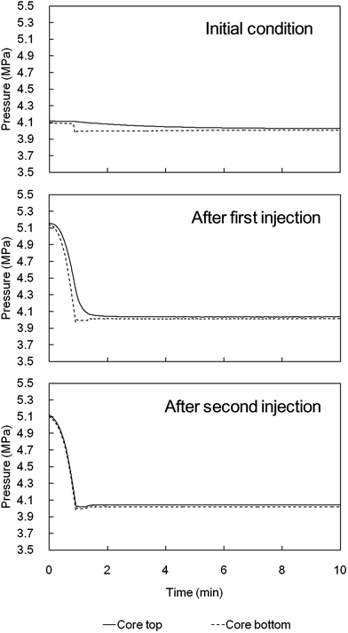 | ||
| Fig. 5 Pressure changes during pressure relaxation tests before fracturing and after forming fractures. | ||
3.4 Applicability of the method
In this study, the fracturing fluid was injected at 5 mL min−1 through an injection port with a diameter of 3 mm. The injection rate can be scaled up to real fields. Currently, the flow capacity of the injection pump for hydraulic fracturing exceeds 100 barrel per min (approximately 15.9 kL min−1) in the petroleum industry. Such pumps can cover the injection area over 22 m2 when the equivalent flow rate is applied, which is sufficient to cover the target stratum in real fields.Recent studies on the strength of hydrate and hydrate-bearing sediments indicate that the fracturing pressure of hydrate-bearing sediments highly depends on the following factors: crystallinity, grain size of the crystals, hydrate morphology, hydrate saturation, and effective stress. In the future, we aim to perform a parametric study of these factors to realize hydraulic fracturing at real reservoirs. For example, hydrate morphology needs to be carefully considered according to the hydrate formation process.30 The partial water saturation method used in this study tends to form grain-cementing hydrates in addition to pore-filling hydrates.22 In contrast, pore-filling or load-bearing hydrates are common in nature, such as in the Nankai Trough.31–33 At low hydrate saturation (<40%), hydrate crystals may shear, detach from the mineral surface, or interfere with rotation during shear deformation.34 Hydrate morphology determines which mechanism performs the key role. Therefore, the tensile strength may be affected by hydrate morphology, particularly at low hydrate saturation. Although the results of this study could be applied to real fields due to the high hydrate saturation (72%), the effect of hydrate morphology should be investigated when considering their application to low-saturated hydrate reservoirs.
It can be noted that real reservoirs have various host sediments such as unconsolidated sand, silt, clay, and consolidated sandstone. If the host sediment is unconsolidated silt/clay or consolidated sandstone, proppants are required to hold the fractures open. The necessity of proppants should be investigated according to the host sediments.
4. Conclusions
The hydraulic fracturing test was conducted using distilled water for a methane-hydrate-bearing sandy core formed in a triaxial pressure cell. The fracturing pressure was 2.9–3.9 MPa above the minimum principal stress. Although the host sediment was unconsolidated, the observed fracture behavior yielded a consolidated-rock-like fracturing mode, i.e., the tensile failure mode. In general, in unconsolidated rocks, the dominant mode of fracturing was shear failure.35,36 The high-permeable feature of unconsolidated rocks leads to infiltration of the fracturing fluid and results in the generation of shear stress inside the sediments. In contrast, the initial effective permeability of hydrate-bearing sand was of sub milli-darcy order, although the absolute permeability of sand was of darcy order. The fracturing behavior of hydrate-bearing sediments was affected by this low-permeable feature at the initial condition and yielded a consolidated-rock-like fracturing mode.The permeability was increased after fracturing and was maintained even after re-confining and closing the fractures. The lack of requirements of chemicals and proppants in the fracturing fluid is favorable from both economical and environmental viewpoints. An effective permeability higher than the value between 1 and 10 mD is a good candidate for gas production via the depressurization method.10 Based on the permeability increase shown in this experiment, hydraulic fracturing is promising as a well stimulation method for low-permeable gas hydrate reservoirs.
Acknowledgements
This study was financially supported by the Research Consortium for Methane Hydrate Resources in Japan (MH21 Research Consortium) to carry out Japan's Methane Hydrate R&D Program conducted by the Ministry of Economy, Trade and Industry (METI). We gratefully acknowledge the financial support and permission provided to present this paper. We also thank Prof. T. Ito of Tohoku Univ. and Dr M. Kida of AIST for fruitful discussions. The comments of the anonymous reviewers helped us to significantly improve the quality of our study. We wish to express our strong appreciation.References
- E. D. Sloan and C. A. Koh, Clathrate Hydrates of Natural Gases, CRC, Boca Raton, FL, 3rd edn, 2008 Search PubMed.
- R. Boswell, Is Gas Hydrate Energy Within Reach?, Science, 2009, 325, 957–958 CrossRef CAS PubMed.
- D. Archer, B. Buffett and V. Brovkin, Ocean methane hydrates as a slow tipping point in the global carbon cycle, Proc. Natl. Acad. Sci. U. S. A., 2009, 106(49), 20596–20601 CrossRef CAS PubMed.
- R. Boswell and T. S. Collett, Current perspectives on gas hydrate resources, Energy Environ. Sci., 2011, 4, 1206–1215 CAS.
- D. F. McGinnis, J. Greinert, Y. Artemov, S. E. Beaubien and A. Wüest, Fate of rising methane bubbles in stratified waters: How much methane reaches the atmosphere?, J. Geophys. Res., 2006, 111, C09007 CrossRef.
- A. Skarke, C. Ruppel, M. Kodis, D. Brothers and E. Lobecker, Widespread methane leakage from the sea floor on the northern US Atlantic margin, Nat. Geosci., 2014, 7, 657–661 CrossRef CAS.
- H. Daigle, N. L. Bangs and B. Dugan, Transient hydraulic fracturing and gas release in methane hydrate settings: A case study from southern Hydrate Ridge, Geochem., Geophys., Geosyst., 2011, 12, Q12022 Search PubMed.
- K. E. Fauria and A. W. Rempel, Gas invasion into water-saturated, unconsolidated porous media: Implications for gas hydrate reservoirs, Earth Planet. Sci. Lett., 2011, 312, 188–193 CrossRef CAS.
- Z.-H. Jin, S. E. Johnson and A. E. Cook, Crack extension induced by dissociation of fracture-hosted methane gas hydrate, Geophys. Res. Lett., 2015, 42, 8522–8529 CrossRef CAS.
- Y. Konno, Y. Masuda, Y. Hariguchi, M. Kurihara and H. Ouchi, Key Factors for Depressurization-Induced Gas Production from Oceanic Methane Hydrates, Energy Fuels, 2010, 24, 1736–1744 CrossRef CAS.
- K. Sasaki, S. Ono, Y. Sugai, T. Ebinuma, H. Narita and T. Yamaguchi, Gas production system from methane hydrate layers by hot water injection using dual horizontal wells, J. Can. Pet. Technol., 2009, 48(10), 21–26 CrossRef CAS.
- J. M. Schicks, E. Spangenberg, R. Giese, B. Steinhauer, J. Klump and M. Luzi, New Approaches for the Production of Hydrocarbons from Hydrate Bearing Sediments, Energies, 2011, 4, 151–172 CrossRef CAS.
- J. M. Schicks, E. Spangenberg, R. Giese, M. Luzi-Helbing, M. Priegnitz and B. Beeskow-Strauch, A Counter-Current Heat-Exchange Reactor for the Thermal Stimulation of Hydrate-Bearing Sediments, Energies, 2013, 6, 3002–3016 CrossRef CAS.
- Y. Konno, Y. Jin, K. Shinjou and J. Nagao, Experimental evaluation of the gas recovery factor of methane hydrate in sandy sediment, RSC Adv., 2014, 4(93), 51666–51675 RSC.
- Y. Konno, Y. Masuda, K. Akamine, M. Naiki and J. Nagao, Sustainable gas production from methane hydrate reservoirs by the cyclic depressurization method, Energy Convers. Manage., 2016, 108, 439–445 CrossRef CAS.
- Y. Song, L. Zhang, Q. Lv, M. Yang, Z. Ling and J. Zhao, Assessment of gas production from natural gas hydrate using depressurization, thermal stimulation and combined methods, RSC Adv., 2016, 6, 47357–47367 RSC.
- J.-C. Feng, Y. Wang and X.-S. Li, Hydrate dissociation induced by depressurization in conjunction with warm brine stimulation in cubic hydrate simulator with silica sand, Appl. Energy, 2016, 174, 181–191 CrossRef CAS.
- T. Ito, A. Igarashi, K. Suzuki, S. Nagakubo, M. Matsuzawa and K. Yamamoto, Laboratory Study of Hydraulic Fracturing Behavior in Unconsolidated Sands for Methane Hydrate Production, Proceedings of the 2008 Offshore Technology Conference, Houston, Texas, U. S. A, 5–8 May 2008 Search PubMed.
- Y. Konno, J. Yoneda, K. Egawa, T. Ito, Y. Jin, M. Kida, K. Suzuki, T. Fujii and J. Nagao, Permeability of sediment cores from methane hydrate deposit in the Eastern Nankai Trough, Mar. Pet. Geol., 2015, 66, 487–495 CrossRef CAS.
- S. Uchida, A. Klar and K. Yamamoto, Sand production model in gas hydrate-bearing sediments, International Journal of Rock Mechanics & Mining Sciences, 2016, 86, 303–316 Search PubMed.
- Y. Konno, Y. Jin, T. Uchiumi and J. Nagao, Multiple-pressure-tapped core holder combined with X-ray computed tomography scanning for gas–water permeability measurements of methane-hydrate-bearing sediments, Rev. Sci. Instrum., 2013, 84, 064501 CrossRef PubMed.
- W. F. Waite, J. C. Santamarina, D. D. Cortes, B. Dugan, D. N. Espinoza, J. Germaine, J. Jang, J. W. Jung, T. J. Kneafsey, H. Shin, K. Soga, W. J. Winters and T.-S. Yun, Physical properties of hydrate-bearing sediments, Rev. Geophys., 2009, 47, RG4003 CrossRef.
- J. W. Jung and J. C. Santamarina, Hydrate adhesive and tensile strengths, Geochem., Geophys., Geosyst., 2011, 12, Q08003 CrossRef.
- S.-L. Li, C.-Y. Sun, G.-J. Chen, Z.-Y. Li, Q.-L. Ma, L.-Y. Yang and A. K. Sum, Measurements of hydrate film fracture under conditions simulating the rise of hydrated gas bubbles in deep water, Chem. Eng. Sci., 2014, 116, 109–117 CrossRef CAS.
- J. Wu, F. Ning, T. T. Trinh, S. Kjelstrup, T. J. H. Vlugt, J. He, B. H. Skallerud and Z. Zhang, Mechanical instability of monocrystalline and polycrystalline methane hydrates, Nat. Commun., 2015, 6, 8743 CrossRef CAS PubMed.
- P. Kerkar, K. W. Jones, R. Kleinberg, W. B. Lindquist, S. Tomov, H. Feng and D. Mahajan, Direct observations of three dimensional growth of hydrates hosted in porous media, Appl. Phys. Lett., 2009, 95, 024102 CrossRef.
- P. B. Kerkar, K. Horvat, K. W. Jones and D. Mahajan, Imaging methane hydrates growth dynamics in porous media using synchrotron X-ray computed microtomography, Geochem., Geophys., Geosyst., 2014, 15, 4759–4768 CrossRef CAS.
- K. Miyazaki, A. Masui, Y. Sakamoto, K. Aoki, N. Tenma and T. Yamaguchi, Triaxial compressive properties of artificial methane-hydrate-bearing sediment, J. Geophys. Res., 2011, 116, B06102 Search PubMed.
- J. Yoneda, A. Masui, Y. Konno, Y. Jin, K. Egawa, M. Kida, T. Ito, J. Nagao and N. Tenma, Mechanical properties of hydrate-bearing turbidite reservoir in the first gas production test site of the Eastern Nankai Trough, Mar. Pet. Geol., 2015, 66, 471–486 CrossRef.
- J.-H. Choi, S. Dai, J.-H. Cha and Y. Seol, Laboratory formation of noncementing hydrates in sandy sediments, Geochem., Geophys., Geosyst., 2014, 15, 1648–1656 CrossRef CAS.
- Y. Konno, Y. Jin, J. Yoneda, M. Kida, K. Egawa, T. Ito, K. Suzuki and J. Nagao, Effect of methane hydrate morphology on compressional wave velocity of sandy sediments: Analysis of pressure cores obtained in the Eastern Nankai Trough, Mar. Pet. Geol., 2015, 66, 425–433 CrossRef.
- J. C. Santamarina, S. Dai, M. Terzariol, J. Jang, W. F. Waite, W. J. Winters, J. Nagao, J. Yoneda, Y. Konno, T. Fujii and K. Suzuki, Hydro-bio-geomechanical properties of hydrate-bearing sediments from Nankai Trough, Mar. Pet. Geol., 2015, 66, 434–450 CrossRef.
- Y. Jin, Y. Konno, J. Yoneda, M. Kida and J. Nagao, In situ Methane Hydrate Morphology Investigation: Natural Gas Hydrate-Bearing Sediment Recovered from the Eastern Nankai Trough Area, Energy Fuels, 2016, 30(7), 5547–5554 CrossRef CAS.
- T. S. Yun, J. C. Santamarina and C. Ruppel, Mechanical properties of sand, silt, and clay containing tetrahydrofuran hydrate, J. Geophys. Res., 2007, 112, B04106 CrossRef.
- A. K. Panah and E. Yanagisawa, Laboratory studies on hydraulic fracturing criteria in soil, Soils and Foundations, 1989, 29(4), 14–22 CrossRef.
- B. Bohloli and C. J. de Pater, Experimental study on hydraulic fracturing of soft rocks: Influence of fluid rheology and confining stress, J. Pet. Sci. Eng., 2006, 53, 1–12 CrossRef CAS.
| This journal is © The Royal Society of Chemistry 2016 |

