 Open Access Article
Creative Commons Attribution 3.0 Unported Licence
Self-optimisation of the final stage in the synthesis of EGFR kinase inhibitor AZD9291 using an automated flow reactor†
Nicholas
Holmes
a,
Geoffrey R.
Akien
ab,
A. John
Blacker
ac,
Robert L.
Woodward
d,
Rebecca E.
Meadows
d and
Richard A.
Bourne
*acd
aInstitute of Process Research and Development, School of Chemistry, University of Leeds, Leeds, LS2 9JT, UK. E-mail: r.a.bourne@leeds.ac.uk
bDepartment of Chemistry, Faraday Building, Lancaster University, Lancaster, LA1 4YB, UK
cSchool of Chemical and Process Engineering, University of Leeds, Leeds, LS2 9JT, UK
dAstraZeneca Pharmaceutical Development, Silk Road Business Park, Macclesfield, SK10 2NA, UK
First published on 24th May 2016
Abstract
Self-optimising flow reactors combine online analysis with evolutionary feedback algorithms to rapidly achieve optimum conditions. This technique has been applied to the final bond-forming step in the synthesis of AZD9291, an irreversible epidermal growth factor receptor kinase inhibitor developed by AstraZeneca. A four parameter optimisation of a telescoped amide coupling followed by an elimination reaction was achieved using at-line high performance liquid chromatography. Optimisations were initially carried out on a model compound (2,4-dimethoxyaniline) and the data used to track the formation of various impurities and ultimately propose a mechanism for their formation. Our protocol could then be applied to the optimisation of the 2-step telescoped reaction to synthesise AZD9291 in 89% yield.
Introduction
To achieve effective optimisation of a reaction process, careful consideration is needed of the various synergistic interactions that occur between reaction variables such as temperature, reaction time and reagent concentration. It is important to ensure that suitable parameter-defining experiments have been carried out during the course of process development to deliver a robust process that can be easily transferred to a manufacturing facility. Design of experiments (DoE) is a commonly used approach which implements statistical methods to screen and optimise a reaction, particularly for problematic steps. For example, the final step of the synthesis of the Src kinase inhibitor saracatinib, a nucleophilic aromatic substitution between a fluoroaniline and an alcohol, was optimised using a fractional factorial DoE.1 The optimisation provided enough information about the reaction system to increase the yield by more than 25% on a 300 kg scale. DoE has been used to optimise reaction steps in the synthesis of many pharmaceutical products including vestipitant,2 raltegravir,3 otenebant,4 denagliptin,5 levovirin,6 delafloxacin7 and continuous processes towards doxercalciferol,8 bendamustime,9 pyrazinamide10 and PARP-1 inhibitors.11However, there has been academic development in substituting DoE with evolutionary algorithms in automated reactors to find optimum conditions. These “self-optimising” reactors incorporate online analysis with a feedback control loop, which uses an optimising algorithm to keep generating new conditions until an optimum is reached. Flow systems are ideally suited for such experimentation, as integration of analytical equipment is facile and measurement and adjustment of operating parameters such as flow rate, temperature and pressure can be accomplished rapidly within a single reactor system.12 The concept was first introduced by Krishnadasan et al.13 for the synthesis of CdSe quantum dot nanoparticles in microreactors with online UV and SNOBFIT (Stable Noisy Optimisation by Branch and Fit) algorithm.14 Latterly the Jensen,15,16 Poliakoff,17,18 and Cronin19 groups have combined online chromatography and spectroscopy, with simplex algorithms20 for the optimisation of small organic molecules. This article demonstrates the applicability of using this approach for complex systems including telescoped reactions for the synthesis of pharmaceuticals.
Herein is described the optimisation, using an automated reactor and adaptive feedback control, of the final bond-forming step in the synthesis of 3 (AZD9291 acrylamide, generic name osimertinib), an irreversible epidermal growth factor receptor (EGFR) kinase inhibitor (Fig. 1).21 The reactor set-up includes 3 separate reagent pumps, which meet in two mixing tees before entering the tubular reactor. The reaction mixture leaves the reactor through a filter then enters a sample loop, which delivers an aliquot of reaction mixture to the mobile phase of the HPLC, without prior quench or dilution. The whole reactor is maintained under fixed back-pressure. The reactor has active heating and cooling, significantly reducing the time taken to reach the set conditions and is controlled by a custom written MatLab program and optimised using the SNOBFIT algorithm.14
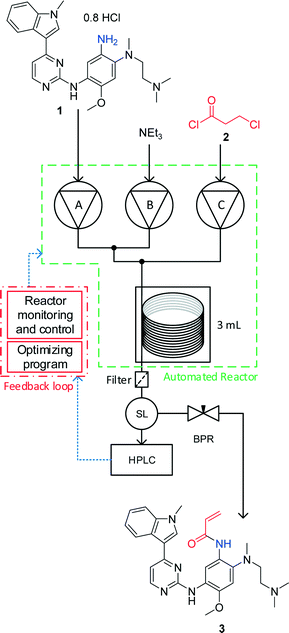 | ||
| Fig. 1 An automated flow reactor with adaptive feedback control and optimisation algorithm (see ESI† for full experimental details). The reagents are fed into the reactor using piston pumps and meet in two separate tee-pieces. The reaction stream leaves the reactor through a filter and is sampled by a sample loop (SL) with online HPLC before the product is collected. The reactor is maintained under fixed 250 psi back pressure. Reaction monitoring and feedback control is carried out using a MatLab interface. The SNOBFIT algorithm calculates conditions based on the calculated HPLC yield. | ||
SNOBFIT is a branch and fit algorithm that plots random points until there is enough data to fit a polynomial to improve on the existing optimum. It is then able to generate new sets of conditions to concurrently improve on the optimum or polynomial fit; or explore empty space. The algorithm was chosen as it generates a scatter of data across the experimental area so a response surface can also be fitted in addition to the optimisation.
Results and discussion
Model optimisation
Initial optimisations were carried out on a model compound, 2,4-dimethoxyaniline 4, to gain understanding of the reaction without consuming high value material and provide initial boundary conditions for the AZD9291 optimisation. The reaction proceeds via formation of the β-chloroamide 5 by a base mediated reaction of the aniline 4 with acid chloride 2, followed by elimination to yield the acrylamide 6 (Scheme 1). Aniline 1 is highly nucleophilic due to the high electron density on the aromatic ring and so it was important to choose a model aniline with electron donating groups. A solvent composition of acetonitrile and water (7![[thin space (1/6-em)]](https://www.rsc.org/images/entities/char_2009.gif) :
:![[thin space (1/6-em)]](https://www.rsc.org/images/entities/char_2009.gif) 2, v
2, v![[thin space (1/6-em)]](https://www.rsc.org/images/entities/char_2009.gif) :
:![[thin space (1/6-em)]](https://www.rsc.org/images/entities/char_2009.gif) v) was used for the pump reservoir solutions, with the exception of the acid chloride, which was prepared in anhydrous acetonitrile. This was selected according to the current batch procedure for synthesising 3. Although competing hydrolysis of the acid chloride occurred in the reaction mixture, an aqueous solution was required to dissolve the resultant triethylammonium chloride.
v) was used for the pump reservoir solutions, with the exception of the acid chloride, which was prepared in anhydrous acetonitrile. This was selected according to the current batch procedure for synthesising 3. Although competing hydrolysis of the acid chloride occurred in the reaction mixture, an aqueous solution was required to dissolve the resultant triethylammonium chloride.
The reaction yield, measured using at-line HPLC, was optimised using the SNOBFIT algorithm, with the flow rate of the aniline 4 (pump A), molar equivalents of acid chloride 2 (pump C – wrt aniline), triethylamine (pump B – eq., wrt acid chloride) and the reactor temperature as variables. An excess of triethylamine was used to ensure there was sufficient to quench the HCl. Other reaction variables such as substrate concentration and residence time are confounded within the flow rates and equivalents, therefore contributing to the algorithms choice of optimum conditions without increasing the computational expense of added variables. An internal standard of biphenyl was added to the aniline solution for the algorithm to calculate a real-time yield by maximising the ratio between the acrylamide 6 and biphenyl peaks. Percentage yields are quoted as HPLC area % of aniline derived material. The optimisation variable limits are displayed in Table 1.
| Limit | Pump A/mL min−1 | Pump B/eq. | Pump C/eq. | Temperature/°C |
|---|---|---|---|---|
| Pump A reservoir 0.241 mol L−1 aniline 4, 0.0156 mol L−1 biphenyl, pump B reservoir 3.73 mol L−1 triethylamine, pump C reservoir 1.00 mol L−1 acid chloride 2. | ||||
| Min | 0.100 | 4.5 | 0.9 | 0 |
| Max | 0.500 | 20 | 2.1 | 130 |
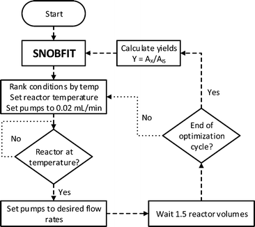
It was important to include material minimisation steps to reduce flows whilst waiting for the reactor temperature to be reached and equilibrate (Fig. 2). This ensured that minimal costly material was not wasted whilst the reactor was reaching temperature. The Polar Bear Plus reactor used has active cooling which significantly decreased the time required to reduce the temperature. Waiting for the reactor to reach temperature was the biggest contribution to the overall optimisation duration and ultimately influenced the decision to use the SNOBFIT algorithm. The algorithm generates sets of experiments, configured to be of 4/5, and these were performed in order of ascending temperature. HPLC was used for analysis as it is ideally suited for quantification of the complex range of species generated. Other work has used analyses with much shorter acquisition times,16,18,19,22 but due to the complex mixture would require detailed chemometric modelling to enable quantification. Due to the sets of experiments delivered by the SNOBFIT algorithm, conditions could be set and next reaction started as soon as the HPLC sample was introduced, and therefore before analysis was completed, and so the HPLC analysis had a very minor effect on the overall optimisation duration.
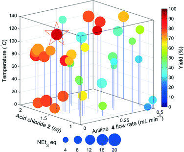
The results of the yield optimisation are displayed in Fig. 3. The optimum conditions are 0.1 mL min−14, 117.8 °C, 1.7 equivalents of 2, 16 equivalents of triethylamine and a residence time of 12.2 min, generating 6 in a 92% yield. A low aniline flow rate correlates to an increase in the residence time and higher yields are achieved at higher temperatures. The excess of 2 is likely to compensate for the competing hydrolysis reaction and high equivalents of triethylamine are possibly required to accelerate the slower elimination step. Further scrutiny of the HPLC chromatograms show >99% conversion of 4 in each reaction with the other main component being the intermediate 5, highlighting that the elimination step is probably rate limiting. In the optimum chromatogram, complete conversion of 4 is achieved with the resulting impurities totalling 8% (2.7% 5). Prior to the optimisation, a batch synthesis of 6 generated the desired product in 76% isolated yield with 1.5 eq. 2, 2.5 eq. NEt3 and stirring at 0 °C for 3 hours.
Impurity identification and optimisation
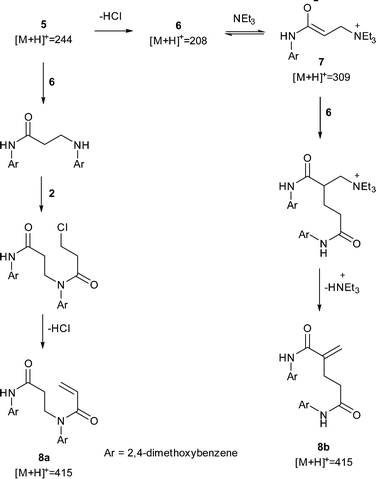
Using the optimisation data, it was possible to create multi-dimensional plots for all the significant impurities observed by HPLC, and find the experimental space where impurity yield is high. These were identified using offline LC-MS and by comparing the relative retention times with known impurity standards in the AZD9291 HPLC method. An impurity of particular concern in the AZD9291 route was known to be a dimer. In our model system, a dimeric impurity with a molecular weight equivalent to two monomers of 6 was also detected. Two potential mechanisms were proposed leading to dimeric species: nucleophilic substitution between 5 and 4 followed by amidation with 2 and subsequent elimination to give dimer 8a; and a Rauhut–Currier mechanism23 (a variation on the Baylis–Hillman reaction)24via the enolate 7 to give dimer 8b (Scheme 2). One of the impurities in the LC-MS analysis had a mass of m/z 309 and further LC-MS-MS analysis showed a fragment of m/z 208 in the second MS spectrum. These data suggest that this impurity is the enolate 7. LC-MS-MS analysis of the dimer showed a peak at m/z 437 corresponding to the Na adduct of 8 and a fragment at m/z 230 suggesting loss of the acrylamide fragment only found in dimer 8a indicating that nucleophilic substitution is the route to the undesired dimer.Another optimization was run, to maximize the amount of 7, and find experimental regions where the impurity formation is high. The yields of the impurity from the original optimization were inputted to SNOBFIT as preliminary data and the algorithm continued from the last data set shown in Fig. 3.
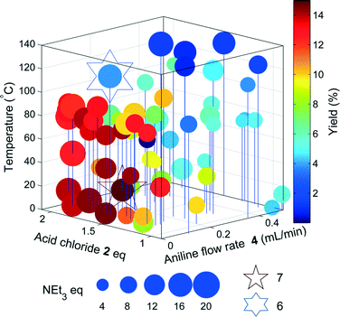
Unsurprisingly, the optimum region of 7 (Fig. 4) is similar to that of the acrylamide 6, as the acrylamide is a precursor for the formation of the enolate. However, 7 is formed in higher yields at much lower temperatures, most likely due to increased temperatures favouring the acrylamide 6 in this equilibrium.
Despite the increased yields obtained through the optimisation, it was not possible to isolate enolate 7 for full characterisation.
AZD9291 acrylamide optimisation
The data obtained from the model compound was used for designing the optimisation of AZD9291 acrylamide 3. The same reactor set-up and reaction route was used as the above transformations, with the exception of the aniline substrate used. A solution of the hydrochloride salt of 1 (0.8 HCl) was used as the free aniline had very low solubility in the solvent mixture. The optimisation limits are displayed in Table 2, the flow rates of which correspond to a calculated residence time between 4 and 22 minutes. The temperature range has increased from the model compound as poor conversion of 1 was achieved during initial experiments at lower temperatures.| Limit | Pump A/mL min−1 | Pump B/eq. | Pump C/eq. | Temperature/°C |
|---|---|---|---|---|
| Pump A reservoir 0.136 mol L−1 aniline 1, 0.0255 mol L−1 biphenyl, pump B reservoir 1.20 mol L−1 triethylamine, pump C reservoir 0.500 mol L−1 acid chloride 2. | ||||
| Min | 0.080 | 2.2 | 0.75 | 80 |
| Max | 0.150 | 15 | 3.0 | 150 |
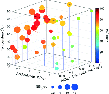
The results of the yield optimisation are displayed in Fig. 5. The optimum conditions (0.11 mL min−11, 2.65 eq. 2, 10.5 eq. NEt3, 123.9 °C, 9.36 min in 89%) are slightly different to that of the model compound. The optimum point for our model system was at the lowest flow rate of the aniline, thereby maximising the residence time, however, the flow rate of 1 is towards the middle of the limits. Fig. 4 shows a clear interrelationship between the flow rate of 1 and the temperature required for high yield. The productivity of the reactor system can be significantly increased, if the flow rate of 1 is increased a corresponding increase in reaction temperature can be used to maintain a high yield with only marginal decreases from the maximum observed yield.
The optimum region requires high equivalents of 2 unlike the model compound and exhibits a higher temperature dependence. This is possibly due to the lower reactivity of 1 compared to the less substituted model compound resulting in greater competition from the hydrolysis of 2. In addition the pre-equilibrium (to deprotonate the HCl salt of 1) and amide coupling steps may be mixing sensitive and may consequently require high flow rates through the mixing tees as mixing increases with flow rate through a tee-piece.25 The material minimisation functions improved the efficiency of material use, calculations showed a reduction in material use of 22%.
Conclusions
Presented is the novel application of implementing a self-optimising automated flow reactor for a 2-step telescope in the synthesis of an active pharmaceutical ingredient. The concept was tested on a model substrate, which aided experimental set-up and data analysis for the optimisation of 3. The model optimisations also provided enough information to be able to predict impurity formation mechanisms and optimised the synthesis of the model compound 6 to a yield of 92%. The second optimisation provided conditions to generate 3 in 89% yield. Overall, the rapid automated optimisation of 3 required 42 separate experiments, which used 10 g of material and overall run time of 26 hours (average of ~240 mg per experiment). The use of self-optimising systems allows swift exploration and process optimisation even of multistage reaction systems without human intervention. Crucially, this enables researchers to focus their effort on the scientifically challenging aspects whilst the automation system performs the routine experimentation.Acknowledgements
The authors would like to thank Simon Pointon, Gwydion Churchill, Martin Jones, Mubina Mohamed, Anne O′Kearney-McMullan and the AZD9291 team for technical support. We would also like to thank Martin Huscroft, Anthony Bristow, Andrew Ray and Simon Barrett for analytical support, Matthew Broadbent for workshop support as well as Katherine Jolley, Jessica Breen and Bao Nguyen. NH thanks the EPSRC, AstraZeneca and University of Leeds for a DTG CASE funded studentship. RAB thanks the Royal Academy of Engineering for funding an industrial secondment at AstraZeneca.References
- S. A. Raw, B. A. Taylor and S. Tomasi, Org. Process Res. Dev., 2011, 15, 688–692 CrossRef CAS.
- G. Guercio, S. Bacchi, M. Goodyear, A. Carangio, F. Tinazzi and S. Curti, Org. Process Res. Dev., 2008, 12, 1188–1194 CrossRef CAS.
- G. R. Humphrey, P. J. Pye, Y.-L. Zhong, R. Angelaud, D. Askin, K. M. Belyk, P. E. Maligres, D. E. Mancheno, R. A. Miller, R. A. Reamer and S. A. Weissman, Org. Process Res. Dev., 2010, 15, 73–83 CrossRef.
- J. A. Ragan, D. E. Bourassa, J. Blunt, D. Breen, F. R. Busch, E. M. Cordi, D. B. Damon, N. Do, A. Engtrakul, D. Lynch, R. E. McDermott, J. A. Mongillo, M. M. O'Sullivan, P. R. Rose and B. C. Vanderplas, Org. Process Res. Dev., 2009, 13, 186–197 CrossRef CAS.
- R. B. Appell, L. T. Boulton, E. D. Daugs, M. Hansen, C. H. Hanson, J. Heinrich, C. Kronig, R. C. Lloyd, D. Louks, M. Nitz, C. Praquin, J. A. Ramsden, H. Samuel, M. Smit and M. Willets, Org. Process Res. Dev., 2012, 17, 69–76 CrossRef.
- P. Zhang, Z. E. Dong and T. P. Cleary, Org. Process Res. Dev., 2005, 9, 583–592 CrossRef CAS.
- R. Hanselmann, G. Johnson, M. M. Reeve and S.-T. Huang, Org. Process Res. Dev., 2008, 13, 54–59 CrossRef.
- B. G. Anderson, W. E. Bauta and W. R. Cantrell, Org. Process Res. Dev., 2012, 16, 967–975 CrossRef CAS.
- J. Chen, K. Przyuski, R. Roemmele and R. P. Bakale, Org. Process Res. Dev., 2014, 18, 1427–1433 CrossRef CAS.
- R. J. Ingham, C. Battilocchio, J. M. Hawkins and S. V. Ley, Beilstein J. Org. Chem., 2014, 10, 641–652 CrossRef PubMed.
- P. Filipponi, C. Ostacolo, E. Novellino, R. Pellicciari and A. Gioiello, Org. Process Res. Dev., 2014, 18, 1345–1353 CrossRef CAS.
- N. Holmes and R. A. Bourne, in Chemical Process Technology for a Sustainable Future, ed. T. M. Letcher, J. L. Scott and D. A. Paterson, RSC Publishing, 1st edn, 2014, ch. 3, pp. 28–45 CrossRef CAS PubMed; M. Rasheed and T. Wirth, Angew. Chem., Int. Ed., 2011, 50, 357–358 CrossRef CAS PubMed; S. V. Ley, D. E. Fitzpatrick, R. J. Ingham and R. M. Myers, Angew. Chem., Int. Ed., 2015, 54, 3449–3464 CrossRef PubMed; S. V. Ley, D. E. Fitzpatrick, R. M. Myers, C. Battilocchio and R. J. Ingham, Angew. Chem., Int. Ed., 2015, 54, 10122–10136 CrossRef PubMed; D. C. Fabry, E. Sugiono and M. Rueping, React. Chem. Eng., 2016, 1, 129–133 Search PubMed.
- S. Krishnadasan, R. J. C. Brown, A. J. de Mello and J. C. de Mello, Lab Chip, 2007, 7, 1434–1441 RSC.
- W. Huyer and A. Neumaier, ACM Trans. Math. Softw., 2008, 35, 1–25 CrossRef.
- J. P. McMullen and K. F. Jensen, Org. Process Res. Dev., 2010, 14, 1169–1176 CrossRef CAS; J. P. McMullen, M. T. Stone, S. L. Buchwald and K. F. Jensen, Angew. Chem., Int. Ed., 2010, 49, 7076–7080 CrossRef PubMed; B. J. Reizman and K. F. Jensen, Chem. Commun., 2015, 51, 13290–13293 RSC.
- J. S. Moore and K. F. Jensen, Org. Process Res. Dev., 2012, 16, 1409–1415 CrossRef CAS.
- A. J. Parrott, R. A. Bourne, G. R. Akien, D. J. Irvine and M. Poliakoff, Angew. Chem., Int. Ed., 2011, 50, 3788–3792 CrossRef CAS PubMed; R. A. Bourne, R. A. Skilton, A. J. Parrott, D. J. Irvine and M. Poliakoff, Org. Process Res. Dev., 2011, 15, 932–938 CrossRef; D. N. Jumbam, R. A. Skilton, A. J. Parrott, R. A. Bourne and M. Poliakoff, J. Flow Chem., 2012, 2, 24–27 CrossRef; Z. Amara, E. S. Streng, R. A. Skilton, J. Jin, M. W. George and M. Poliakoff, Eur. J. Org. Chem., 2015, 2015, 6141–6145 CrossRef.
- R. A. Skilton, A. J. Parrott, M. W. George, M. Poliakoff and R. A. Bourne, Appl. Spectrosc., 2013, 67, 1127–1131 CrossRef CAS PubMed.
- V. Sans, L. Porwol, V. Dragone and L. Cronin, Chem. Sci., 2015, 6, 1258–1264 RSC.
- W. Spendley, G. R. Hext and F. R. Himsworth, Technometrics, 1962, 4, 441–461 CrossRef CAS; J. A. Nelder and R. Mead, Comput. J., 1965, 7, 308–313 CrossRef; M. W. Routh, P. A. Swartz and M. B. Denton, Anal. Chem., 1977, 49, 1422–1428 CrossRef.
- M. R. V. Finlay, M. Anderton, S. Ashton, P. Ballard, P. A. Bethel, M. R. Box, R. H. Bradbury, S. J. Brown, S. Butterworth, A. Campbell, C. Chorley, N. Colclough, D. A. E. Cross, G. S. Currie, M. Grist, L. Hassall, G. B. Hill, D. James, M. James, P. Kemmitt, T. Klinowska, G. Lamont, S. G. Lamont, N. Martin, H. L. McFarland, M. J. Mellor, J. P. Orme, D. Perkins, P. Perkins, G. Richmond, P. Smith, R. A. Ward, M. J. Waring, D. Whittaker, S. Wells and G. L. Wrigley, J. Med. Chem., 2014, 57, 8249–8267 CrossRef CAS PubMed; D. Cross, S. Ashton, C. Nebhan, C. Eberlein, M. R. V. Finlay, G. Hughes, V. Jacobs, M. Mellor, M. Red Brewer, C. Meador, J. Orme, P. Spitzler, S. Powell, A. Rahi, P. Taylor, R. A. Ward, P. Daunt, A. Galer, T. Klinowska, G. Richmond and W. Pao, Mol. Cancer Ther., 2013, 12, A109 CrossRef PubMed; D. Wilson, C. Finnie and S. A. Raw, WO2015101791A1, 2015.
- D. E. Fitzpatrick, C. Battilocchio and S. V. Ley, Org. Process Res. Dev., 2016, 20, 386–394 CrossRef CAS; N. Holmes, G. R. Akien, R. J. D. Savage, C. Stanetty, I. R. Baxendale, A. J. Blacker, B. A. Taylor, R. L. Woodward, R. E. Meadows and R. A. Bourne, React. Chem. Eng., 2016, 1, 96–100 Search PubMed.
- M. M. Rauhut and H. Currier, US. Pat., US3074999, 1963 Search PubMed.
- D. Basavaiah, A. J. Rao and T. Satyanarayana, Chem. Rev., 2003, 103, 811–892 CrossRef CAS PubMed; A. B. Baylis and M. E. D. Hillman, Ger. Pat., DE2155113 (A1), 1972 Search PubMed; A. B. Baylis and M. E. D. Hillman, US. Pat., US3743669 (A), 1973 Search PubMed.
- K. D. Nagy, B. Shen, T. F. Jamison and K. F. Jensen, Org. Process Res. Dev., 2012, 16, 976–981 CrossRef CAS; S. Schwolow, J. Hollmann, B. Schenkel and T. Röder, Org. Process Res. Dev., 2012, 16, 1513–1522 CrossRef.
Footnote |
| † Electronic supplementary information (ESI) available. See DOI: 10.1039/c6re00059b |
| This journal is © The Royal Society of Chemistry 2016 |


