 Open Access Article
Creative Commons Attribution 3.0 Unported Licence
Spatial separation of oxidation and reduction co-catalysts for efficient charge separation: Pt@TiO2@MnOx hollow spheres for photocatalytic reactions†
Ang
Li
,
Tuo
Wang
,
Xiaoxia
Chang
,
Weiting
Cai
,
Peng
Zhang
,
Jijie
Zhang
and
Jinlong
Gong
*
Key Laboratory for Green Chemical Technology of Ministry of Education, School of Chemical Engineering and Technology, Collaborative Innovation Center of Chemical Science and Engineering, Tianjin University, Weijin Road 92, Tianjin, 300072, P. R. China. E-mail: jlgong@tju.edu.cn
First published on 26th November 2015
Abstract
Efficient charge separation is a critical factor for solar energy conversion by heterogeneous photocatalysts. This paper describes the complete spatial separation of oxidation and reduction cocatalysts to enhance the efficacy of charge separation and surface reaction. Specifically, we design Pt@TiO2@MnOx hollow spheres (PTM-HSs) with Pt and MnOx loaded onto the inner and outer surface of TiO2 shells, respectively. Pt favours electron trapping, while MnOx tends to collect holes. Upon generation from TiO2, electrons and holes flow inward and outward of the spherical photocatalyst, accumulating on the corresponding cocatalysts, and then take part in redox reactions. Combined with other advantages, such as the large surface area and appropriate pore size, the PTM-HSs exhibit high efficiency for the photocatalytic oxidation of water and benzyl alcohol. The mechanism of the oxidation process of benzyl alcohol over the photocatalyst is also presented.
Introduction
Efficient charge separation is a critical factor for solar energy conversion by semiconductor-based systems. It is crucial for increasing the performance of solar cells, photoelectrochemical and photocatalytic systems.1,2 As an important application, photocatalytic oxidation requires exceptionally efficient charge separation. Within photooxidation reactions, the photooxidation of water into O2 has long been considered as the bottleneck of the water-splitting process, so the invention of highly active water oxidation catalysts is a key step in the development of light-driven water splitting.3 In addition, the photocatalytic oxidation system can also be used to produce highly valued chemicals such as aldehydes and ketones. Compared with traditional methods with high temperature, toxic oxidants and hazardous waste,4 photocatalytic oxidation processes can be performed under mild and environmentally friendly conditions. Substances unstable at high temperatures may also be synthesized by such selective light-assisted processes.4 Recently, the emergence of a new family of metal-free polymer photocatalysts provided fine methods to enhance charge separation.5,6 For instance, heterojunctions between carbon nitride and sulfur-mediated carbon nitride have been constructed to promote photocatalytic reactions.6 Besides, many other strategies were adopted to improve charge separation, while the results remain unsatisfactory because of diverse problems.1,7–9Cocatalyst loading has been proved to be an effective approach to accelerate charge separation.1 Cocatalysts can be designed for oxidation and reduction purposes. Oxidation cocatalysts tend to capture holes (PbO2, MnOx and PdS,10etc.), while reduction cocatalysts prefer electrons (Pt, Pd,1etc.). Meanwhile, they can promote the surface reaction of the redox process.11 Yu et al. have reported the fabrication of TiO2 nanosheets loaded with Pt. Compared with pure TiO2 nanosheets, the photocatalytic activity of Pt decorated nanosheets was obviously improved.2
Simultaneous loading of oxidation and reduction cocatalysts could further improve the photocatalytic activity. Colón et al. fabricated Pt–TiO2/g-C3N4–MnOx composites and successfully proved that Pt and MnOx trap electrons and holes, respectively, leading to a further separation of charges.12 However, both reduction and oxidation cocatalysts are randomly distributed in this case, which results in a random flow direction of charge carriers when they migrate to the cocatalysts. In such a scenario, the possibility of electron–hole recombination will be increased. In addition, the short distance between the reduction and oxidation cocatalysts is unfavorable for redox reactions, for close redox sites may lead to severe back-reactions.
Spatial separation of oxidation and reduction cocatalysts is a method to solve this problem, yet limited success has been reported. Carbon nitride nanosheets have been fabricated to separate different cocatalysts, promoting the locally-incompatible oxidation and reduction reactions on the two surfaces.5 In addition, Pt particles (reduction cocatalyst) and MnOx particles (oxidation cocatalyst) have been nicely deposited on different facets of BiVO4, exhibiting increased performance when compared to the randomly deposited counterparts.1 To achieve more complete spatial separation of oxidation and reduction cocatalysts, as well as to make full use of the photocatalyst, we design and synthesize Pt@TiO2@MnOx hollow spheres (PTM-HSs) with Pt particles and MnOx loaded onto the inner and outer surfaces of TiO2 hollow spheres, respectively. Different cocatalysts can be completely separated by the TiO2 shells without intermixing. The photocatalytic material can be fully used owing to the thin shell (about 40–60 nm) of TiO2 hollow spheres. TiO2 is chosen in this study since it serves as an excellent benchmark photocatalyst for comparison purposes.13–15 Additionally, as a model structure, this concept (i.e., different cocatalysts are separated by TiO2 shells completely) can be extended to other redox cocatalysts such as Au, Ag, PbO2, etc.1
Upon generation from TiO2, electrons and holes will flow inward and outward of the spherical TiO2 shells, respectively, accumulating on corresponding cocatalysts and then taking part in redox reactions (Fig. 1). Electrons can promote the photo-reduction, while holes participate in the photo-oxidation.16 Thus, the oxidation of benzyl alcohol accompanied by the elimination of electrons by O2 is described in Fig. 1a. The reduction and oxidation reactions take place at different sides of the TiO2 shells, which is critical for effective charge separation. In addition, light will pass through the thin TiO2 shell and keep reflecting in the cavity, increasing the scattering length for enhanced light-absorption. Combined with the large surface area, the PTM-HSs exhibit high efficiency for the photocatalytic oxidation of benzyl alcohol, a representative alcohol containing phenyl groups. Generally, the appropriate catalysts for benzyl alcohol oxidation can also perform well in the oxidation of other similar chemicals.17 Thus, the current photoredox catalysis system can be expanded for other relevant organic synthesis of fine chemicals. Additionally, we propose a two-step photooxidation mechanism for PTM-HSs, which may provide inspiration for the design of similar catalysts with high activity.
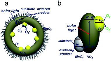 | ||
| Fig. 1 Proposed mechanism for photocatalytic oxidation by PTM-HSs. Pt and MnOx are spatially separated by TiO2. (a) The reaction process. (b) Band structure of the catalyst. | ||
Results and discussion
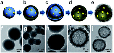
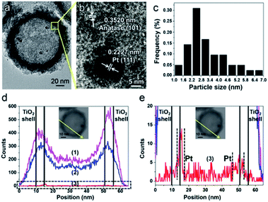
The synthesis of PTM-HSs (Fig. 2) starts from SiO2 nanospheres prepared by a modified Stöber method, with H2PtCl6 adsorbed on the surface of SiO2.18 Then they were calcined at 500 °C for 2 hours (h) under H2 atmosphere to form Pt particles anchored on SiO2 (Fig. 2a and f). Subsequent coating of an amorphous TiO2 shell was performed by the hydrolysis of titanium tert-butoxide (TBOT) (Fig. 2b and g). Then the samples were calcined to improve the crystallinity of TiO2. It should be noted that direct calcination would destroy the structure of the TiO2 shells (Fig. S2†). To preserve the morphology, another layer of SiO2 was added as a coating to form the outermost protective layer (Fig. 2c and h). After calcination, the outer and inner silica layers were removed by NaOH (1.67 M) etching at 70 °C for 8 h to form Pt@TiO2 hollow spheres (PT-HSs) (Fig. 2d and i). Finally, MnOx was selectively deposited on the outer surface of PT-HSs to form PTM-HSs (Fig. 2e and j and S3†) by a photo-deposition method (Fig. S1†).The successful synthesis of the PT-HSs is further validated. Fig. 3a shows that most Pt particles with an average size of ca. 3.2 ± 1.3 nm (Fig. 3c) are uniformly loaded onto the inner surface of TiO2 shells. A few Pt particles agglomerate to form larger ones. The high resolution transmission electron microscopy (HRTEM) image of the area near the inner surface of TiO2 shells (Fig. 3b) shows that the lattice spacing of 0.2227 nm and 0.3520 nm match well with the (111) planes of Pt and the (101) planes of anatase. It can be seen that a hexagonal Pt particle is coated by a layer of TiO2 (Fig. 3b), resulting from the strong interaction between Pt and TiO2. A STEM-energy-dispersive X-ray spectroscopy (EDS) line scan was performed through the center of an individual PT-HS particle (inset in Fig. 3d and e), which further confirms the position of Pt particles relative to the TiO2 shell. Fig. 3d shows strong signals of Ti and O at the edge of the PT-HS, which reveals a typical structure of TiO2 hollow spheres. The TiO2 shell is marked in Fig. 3d by two groups of vertical lines, indicating the wall of the TiO2 shell based on Ti and O signals in the EDS line scan. Fig. 3e shows the magnified Pt EDS signal, demonstrating that Pt particles are loaded onto the inner surface of the TiO2 shell. It is not possible to use an EDS area scan to perform such confirmation because of the low loading of Pt (1%, measured by ICP) (Fig. S4d†).
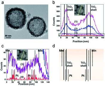
The structure of the PTM-HSs is confirmed by the same method (Fig. 4), where MnOx is identified on the outer surface of TiO2 shells. The universal existence of PTM-HSs can be demonstrated by the TEM image of a larger area (Fig. S3†).
The pore size and Brunauer–Emmett–Teller (BET) surface area of PTM-HSs are measured by N2 adsorption, and determined to be 5.0 nm (average pore size) and 298 m2 g−1, respectively (Fig. S5a†). The results indicate a mesoporous structure, which is the prerequisite for effective immigration of reactants. Additionally, X-ray diffraction (XRD, Fig. S5b†) and HRTEM of the spine-like layer (Fig. S5c and d†) prove that the PTM-HSs consist of Pt, anatase and MnOx, where x is between 1.0 and 2.0. Highly crystallized anatase instead of a rutile shell is formed, which is capable of achieving higher photocatalytic activity.19,20 The components of the catalysts can be further confirmed by X-ray photoelectron spectroscopy (XPS, Fig. S8†).
For comparison, reference catalysts such as pure TiO2 hollow spheres (T-HSs) (Fig. S6a and b†) and TiO2/Pt/MnOx hollow spheres (T/P/M-HSs) (Fig. S6c–f†) were synthesized by a similar method. PT-HSs were also used as reference catalysts. T/P/M-HSs were synthesized by impregnating T-HSs in solutions of H2PtCl6 and MnSO4 in sequence to form a structure in which the Pt particles and MnOx distributed randomly on both the inner and outer surfaces.
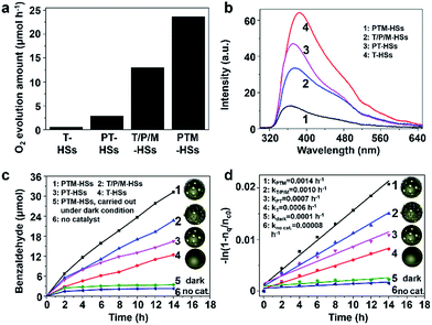
Catalysts containing Pt and TiO2 can exhibit activity in the photooxidation of alcohols (details are discussed in Fig. S12†) and water (Fig. 5a) under visible light, because of the surface plasmonic resonance effect (SPR) of Pt (Fig. S12e†).17,21,22 As shown in Fig. 5a, the highest water oxidation activity is achieved for the PTM-HSs. The deposited Pt on the inner surface can collect electrons to reduce IO3− ions, and the MnOx photo-deposited selectively on the outer surface can accumulate holes for water oxidation. For PT-HSs, although the amounts of loaded species and the topography of the catalysts are similar, the promotion effect of the cocatalysts is not as evident as that of PTM-HSs, indicating that the photocatalytic performance can be greatly enhanced when the reduction/oxidation cocatalysts are spatially separated. The activity of T-HSs and PT-HSs is even lower. These results can be explained by the improvement of the charge separation, which can be demonstrated by the photoluminescence (PL) spectra (Fig. 5b). The emission intensity of T-HSs is the strongest, resulting from the severe recombination of photogenerated charges. In contrast, the intensity of PT-HSs, T/P/M-HSs and PTM-HSs are reduced by about 25%, 45% and 80%, respectively, indicating an enhanced suppression of the recombination process.
To illustrate that the enhancement of activity is indeed caused by the improvement of charge separation, the oxidation of benzyl alcohol was performed under UV light (λ < 420 nm). UV light (1.46 mW cm−2) was adopted to ensure that light absorption remained the same (Fig. S7†) when different catalysts were used. Thus, the influence of light absorption can be eliminated. Benzyl alcohol was oxidized to benzaldehyde without any over-oxidized products such as benzoic acid (explained in Fig. S9†). Besides, the structure of the catalysts remained unchanged after the reaction, indicating excellent stability (Fig. S10†). As shown in Fig. 5c, negligible amounts of benzaldehyde were detected without the catalyst or in the dark condition (traces 5 and 6, Fig. 5c), indicating the importance of catalysts and light. The T-HSs display a moderate photocatalytic activity (trace 4, Fig. 5c, 12.39 μmol of product, 14 h), while the activity of PT-HSs is increased (trace 3, Fig. 5c, 22.72 μmol of product, 14 h). By loading Pt and MnOx simultaneously (T/P/M-HSs), the activity is further enhanced (trace 2, Fig. 5c). The highest activity (31.22 μmol of product, 14 h) is achieved when PTM-HSs were used (trace 1, Fig. 5c). The corresponding study on kinetics (Fig. S14†) shown in Fig. 5d exhibits the same trend (i.e., activity: PTM-HSs > T/P/M-HSs > PT HSs > T-HSs).
To further confirm the enhancement of separation efficiency (ηs), the apparent quantum efficiency (AQE) of PTM-HSs and T/P/M-HSs at 254 nm were determined to be 63.14% and 45.94%, respectively, which is higher than that of conventional TiO2-based catalysts (often in the range 4.3–39%).23 Because of the similar structure of the two kinds of catalysts and the same loading amount of cocatalyst, the efficiency of adsorption (ηa) and surface-reaction (ηc) remain the same between the catalysts (Fig. S7†). Considering the overall efficiency is determined by ηa, ηs and ηc simultaneously, the enhancement of AQE can be attributed to the enhancement of ηs. Thus, we can quantitatively demonstrate that the spatial separation of cocatalysts indeed leads to an efficient charge separation for photocatalytic oxidation. Moreover, even under visible light (λ > 420 nm), the electrons (generated from catalysts containing Pt and TiO2) still flow from TiO2 to Pt (instead of the hot electrons injected into TiO2), which can be proved by a probe experiment (Fig. S12†).
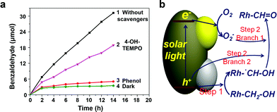
In order to investigate the mechanism of photocatalytic benzyl alcohol oxidation, particularly the main active species, phenol, and 4-hydroxy-2,2,6,6-tetramethylpiperidine 1-oxyl free radical (4-OH-TEMPO) were used as the scavengers of holes (h+) and superoxide radicals (O2−), respectively. As shown in Fig. 6a, when phenol (h+ scavenger) was added into the photocatalytic system, an extremely low oxidation activity was observed, indicating that h+ plays an indispensable role in the oxidation process. However, when 4-OH-TEMPO (O2− scavenger) was added, the activity only partly decreased, indicating that O2− also takes part in the reaction, while it is not indispensable. These observations suggest that two photocatalytic steps might be involved. The first step primarily depends on h+, while the second step is driven by h+ and O2− simultaneously. An intermediate would be formed in step 1 and be oxidized in step 2, bridging the two steps.
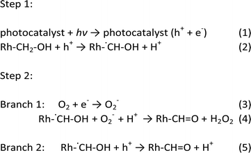
To determine the intermediate species, a kinetic isotope effect (KIE) study was conducted for PTM-HSs with benzyl alcohol under aerobic conditions. The KIE value was 0.78, suggesting the breaking of a C–H bond instead of an O–H bond (see ESI†). Accordingly, the intermediate was determined to be Rh-˙CH–OH (Rh stands for the benzene ring). The speculated mechanism of photocatalytic benzyl alcohol oxidation is shown in Fig. 6b and eqn (1) to (5):
Upon the separation of photo-induced electrons and holes over the PTM-HSs, the holes react with benzyl alcohol molecules to form intermediate free radicals (Rh–˙CH–OH). Subsequently, some of the free radicals react with O2−, while others are further oxidized by holes to form the ultimate products (Rh–CH![[double bond, length as m-dash]](https://www.rsc.org/images/entities/char_e001.gif) O). Meanwhile, oxy species finally exist as H2O2 after a series of changes, which are discussed in detail in the ESI.†24
O). Meanwhile, oxy species finally exist as H2O2 after a series of changes, which are discussed in detail in the ESI.†24
Conclusions
In summary, the PTM-HS catalyst with Pt and MnOx loaded separately onto the inner and outer surfaces of TiO2 hollow spheres was successfully synthesized for the photooxidation of benzyl alcohol. Pt particles favor electron trapping, while MnOx tends to collect holes. The spatial separation of Pt and MnOx by the TiO2 shell greatly enhances the separation of electrons and holes. With this structure, different cocatalysts can be completely separated without intermixing. In addition, the large surface area of the TiO2 shell can provide plenary attachment sites for Pt and MnOx, accelerating the consumption of electrons, which is good for the oxidation of water and benzyl alcohol. Furthermore, considering the multiple improvements of light-absorption, charge-separation and surface catalytic effect, the structure of these PTM-HSs could provide inspiration for other photocatalytic systems such as water splitting and CO2 reduction.Experimental
Materials
H2PtCl6·6H2O (99.9%) was purchased from Tianjin Kaiyingte chemical trade Co., Ltd. Tetraethyl orthosilicate (TEOS, 98%) was purchased from Tianjin Chemical Reagent No. 1 Plant. Titanium tert-butoxide (TBOT, ≥ 98.0%) and undecane (≥99.0%) were purchased from Sinopharm and Guangfu, respectively. Poly(4-vinylpyridine) (PVP), hydroxypropyl cellulose (HPC) and 4-hydroxy-2,2,6,6-tetramethylpiperidine 1-oxyl free radical (4-OH-TEMPO, >98%) were purchased from TCI. Toluene (≥99.5%), benzyl alcohol (≥98.0%) and benzaldehyde (≥98.5%) were purchased from Jiangtian. Phenol (99%) was purchased from J&K. Deionized water (18.25 MΩ cm) supplied by an UP Water Purification System was used in all experimental processes. All chemicals were obtained from commercial suppliers and used without further purification.Characterization
TEM was performed on a JEOL JEM 2100F electron microscope operating at 200 kV. The photoluminescence (PL) spectrum was performed on a Hitachi F-4600 fluorescence spectrophotometer. Crystalline structures were evaluated by XRD analysis using a Bruker D8 Focus operating at 40 kV and 40 mA equipped with nickel-filtered Cu Kα radiation (λ = 1.54056 Å). The BET surface area and pore structure of catalysts were measured using a Micromeritics Tristar 3000 analyzer by nitrogen adsorption at 77 K. The specific surface areas were calculated from the isotherms using the BET method. The pore distribution and the cumulative volumes of pores were obtained by the BJH method from the desorption branch of the adsorption isotherms. XPS was performed under ultrahigh vacuum (<10−6 Pa) on a Kratos XSAM 800 spectrometer with Mg Kα X-ray source (E = 1253.6 eV).Methods
Acknowledgements
We acknowledge the National Natural Science Foundation of China (No. 21222604, U1463205, 21525626, and 51302185), the Program for New Century Excellent Talents in University (NCET-10-0611), the Scientific Research Foundation for the Returned Overseas Chinese Scholars (MoE), and the Program of Introducing Talents of Discipline to Universities (No. B06006) for financial support.Notes and references
- R. Li, F. Zhang, D. Wang, J. Yang, M. Li, J. Zhu, X. Zhou, H. Han and C. Li, Nat. Commun., 2013, 4, 1432–1438 CrossRef PubMed.
- J. Yu, L. Qi and M. Jaroniec, J. Phys. Chem. C, 2010, 114, 13118–13125 CAS.
- L. Duan, F. Bozoglian, S. Mandal, B. Stewart, T. Privalov, A. Llobet and L. Sun, Nat. Chem., 2012, 4, 418–423 CrossRef CAS PubMed.
- J. C. Colmenares and R. Luque, Chem. Soc. Rev., 2014, 43, 765–778 RSC.
- J. Zhang, Y. Chen and X. Wang, Energy Environ. Sci., 2015, 8, 3092–3108 CAS.
- Y. Zheng, L. Lin, B. Wang and X. Wang, Angew. Chem., Int. Ed., 2015, 54, 12868–12884 CrossRef CAS PubMed.
- Y. Hou, F. Zuo, A. Dagg and P. Feng, Nano Lett., 2012, 12, 6464–6473 CrossRef CAS PubMed.
- X. Chang, T. Wang, P. Zhang, J. Zhang, A. Li and J. Gong, J. Am. Chem. Soc., 2015, 137, 8356–8359 CrossRef CAS PubMed.
- J. Liu, X. Yu, Q. Liu, R. Liu, X. Shang, S. Zhang, W. Li, W. Zheng, G. Zhang, H. Cao and Z. Gu, Appl. Catal., B, 2014, 158–159, 296–300 CrossRef CAS.
- H. Yan, J. Yang, G. Ma, G. Wu, X. Zong, Z. Lei, J. Shi and C. Li, J. Catal., 2009, 266, 165–168 CrossRef CAS.
- M. Yoshida, N. Gon, S. Maeda, T. Mineo, K. Nitta, K. Kato, H. Nitani, H. Abe, T. Uruga and H. Kondoh, Chem. Lett., 2014, 43, 1725–1727 CrossRef.
- S. Obregón and G. Colón, Appl. Catal., B, 2014, 144, 775–782 CrossRef.
- J. B. Joo, M. Dahl, N. Li, F. Zaera and Y. Yin, Energy Environ. Sci., 2013, 6, 2082–2092 CAS.
- W. Choi, A. Termin and M. R. Hoffmann, J. Phys. Chem., 1994, 98, 13669–13679 CrossRef.
- A. Li, P. Zhang, X. Chang, W. Cai, T. Wang and J. Gong, Small, 2015, 11, 1892–1899 CrossRef CAS PubMed.
- B. Kraeutler and A. J. Bard, J. Am. Chem. Soc., 1978, 100, 4317–4318 CrossRef CAS.
- Y. Shiraishi, D. Tsukamoto, Y. Sugano, A. Shiro, S. Ichikawa, S. Tanaka and T. Hirai, ACS Catal., 2012, 2, 1984–1992 CrossRef CAS.
- W. Stöber, A. Fink and E. Bohn, J. Colloid Interface Sci., 1968, 26, 62–69 CrossRef.
- A. L. Linsebigler, G. Lu and J. T. Yates Jr, Chem. Rev., 1995, 95, 735–758 CrossRef CAS.
- A. Fujishima, X. Zhang and D. A. Tryk, Surf. Sci. Rep., 2008, 63, 515–582 CrossRef CAS.
- J. Hou, H. Cheng, O. Takeda and H. Zhu, Angew. Chem., 2015, 127, 8600–8604 CrossRef.
- P. Zhang, T. Wang and J. Gong, Adv. Mater., 2015, 27, 5328–5342 CrossRef CAS PubMed.
- S. Higashimoto, N. Kitao, N. Yoshida, T. Sakura, M. Azuma, H. Ohue and Y. Sakata, J. Catal., 2009, 266, 279–285 CrossRef CAS.
- J. C. Colmenares and R. Luque, Chem. Soc. Rev., 2014, 43, 765–778 RSC.
Footnote |
| † Electronic supplementary information (ESI) available. See DOI: 10.1039/c5sc04163e |
| This journal is © The Royal Society of Chemistry 2016 |

