A self-assembly method for the fabrication of a three-dimensional (3D) polypyrrole (PPy)/poly(3,4-ethylenedioxythiophene) (PEDOT) hybrid composite with excellent absorption performance against electromagnetic pollution†
Fan
Wu
*a,
Mengxiao
Sun
ab,
Wanchun
Jiang
a,
Kun
Zhang
ac,
Aming
Xie
*ad,
Yuan
Wang
*a and
Mingyang
Wang
ad
aState Key Laboratory for Disaster Prevention & Mitigation of Explosion & Impact, PLA University of Science and Technology, Nanjing 210007, P. R. China. E-mail: wufanjlg@163.com; wangyuanjlg@163.com; aminghugang@126.com; Tel: +86 25 80825493
bKey Laboratory of Science and Technology on Electromagnetic Environmental Effects and Electro-optical Engineering, PLA University of Science and Technology, Nanjing 210007, P. R. China
cSchool of Chemical Engineering, Nanjing University of Science & Technology, Nanjing 210094, P. R. China
dSchool of Mechanical Engineering, Nanjing University of Science & Technology, Nanjing 210094, P. R. China
First published on 18th November 2015
Abstract
Electromagnetic pollution is second to air and water pollution, and has been considered as the third worldwide hazard. Materials with electromagnetic absorption (EA) performance are the key to protect human beings and wildlife from this pollution. In this study, a composite comprising three-dimensional (3D) polypyrrole (PPy) and poly(3,4-ethylenedioxythiophene) (PEDOT) was prepared via a self-assembly method. This 3D-PPy/PEDOT composite was characterized using field emission scanning electron microscopy (FE-SEM), field emission high resolution transmission electron microscopy (FE-HRTEM), X-ray diffraction (XRD) and Raman spectroscopy. It was found that a composite only consisting of 5 wt% 3D-PPy/PEDOT in a wax matrix exhibited an effective EA bandwidth (deeper than −10 dB) of 6.24 GHz at a thickness of 2.5 mm. Furthermore, the highest effective EA bandwidth of 6.28 GHz can be reached. The results obtained in this study indicate that 3D-PPy/PEDOT is a promising EA material, which can exhibit a broad effective EA bandwidth at a low filler loading and a thin thickness simultaneously.
1. Introduction
Life has evolved under the influence of two omnipresent forces: gravity and electromagnetism. It should be expected that both play important roles in the functional activities of organisms. The development of wireless telecommunication has caused a massive increase in electromagnetic pollution. In recent years, human beings and wildlife have been chronically exposed to microwaves and radiofrequency radiation (RFR) signals. The effects of electromagnetic pollution on human health and wildlife have scarcely been studied.1–5 Therefore, there is an urgent need for effective methods to deal with potential environmental disasters and to help preserve biodiversity in the long-term.Electromagnetic interference (EMI) shielding is considered as an efficient way to protect the human body and electric equipment from electromagnetic pollution. Traditional EMI shielding materials are based on metal films or plates. Although these materials have a good shielding effectiveness against outer electromagnetic fields, they have some obvious drawbacks including their heavy weight, corrosion and poor processibility.6 A good EMI shielding material should prevent both incoming and outgoing EMI.7 Metal based shields will lose their effectiveness when the inner electric equipment generates strong electromagnetic fields by itself, because the electromagnetic waves are totally reflected and self-interference will cause serious potential hazards to arise. On the contrary, electromagnetic absorbers can weaken electromagnetic energy sharply. They make sure that the transmitted electromagnetic waves do not have a harmful effect on human bodies, wildlife or electric equipment. Thus, electromagnetic absorption (EA) is more important than reflection during the development of these shielding materials.
With the development of nanotechnology, dielectric or magnetic materials have been fabricated on the nano-size scale to improve the EA performance, such as ZnO (cagelike,8 nanorods9), CuS,10,11 α-MnO2,12,13 Bi2S3,14 and dendrite-like Fe3O4, γ-Fe2O3 and Fe,15 or their composites, such as NiO/SiC,16,17 Fe3O4@TiO2,18 CdS/α-Fe2O3,19 FexOy@SiO2,20 and Ni@TiO2.21 Other examples include carbon nanomaterials, such as carbon nanotubes (CNTs) and their hybrids,22–25 porous carbon,26,27 carbon nanopowders,28 graphene,29 and reduced graphene oxide (RGO).30–33 However, metal oxides or sulfide based EA composites cannot overcome the high filler loading ratios, and pure carbon material based EA composites cannot get sufficient broad effective EA bandwidths (below −10 dB) with low matching thicknesses, though they give low loading ratios in composites (less than 20.0 wt%).
In addition to the EA materials mentioned above, recently the intrinsically conducting polymers (ICPs), such as poly(3,4-ethylenedioxythiophene) (PEDOT), polyaniline (PANi) and polypyrrole (PPy), are also of great interest as EA materials. Their EA performance can be improved by hybridizing with other semiconductors or magnetic materials, for example, RGO,34,35 Co3O4,36,37 Fe3O4,38 CoFe2O4,39 and barium hexaferrites.40–43 However, many previous works report that composites loaded with only ICPs are not enough to produce sufficient dielectric loss, which brings the problems of narrow effective EA bandwidth and weak absorption.
In the past few years, remarkable progress has been made in the self-assembly of materials into three-dimensional (3D) forms such as hydrogels, aerogels and some other microporous or mesoporous frameworks.44 Fe(NO3)3 can oxidize the monomer pyrrole to produce the conducting PPy hydrogel with super-elasticity through a fast or slow oxidation procedure.45 The as-prepared PPy hydrogels can be easily converted into lightweight and conductive 3D-reticulate materials and show sufficient pollution treatment performance with dyes and solvents.6,45 In this study, the sorbent properties of 3D-PPy for organic solvents were utilized in a self-assembly process to build the 3D-PPy/PEDOT hybrid composite. A 2,5-dibromo-3,4-ethylenedioxythiophene (DBEDOT) solution in methylene chloride (CH2Cl2) was easily absorbed into 3D-PPy, and after gentle heating, DBEDOT was solid-state polymerized (SSP) as PEDOT inside 3D-PPy. This hybrid composite displays a wide effective EA bandwidth with a low matching thickness and filler loading ratio simultaneously. When the filler loading of 3D-PPy/PEDOT is only 5.0 wt% in a wax matrix, this composite can reach an effective EA bandwidth of 6.24 GHz. This indicates the promising application of 3D-PPy/PEDOT composites in the field of EA.
2. Experimental section
2.1. Materials
Glacial acetic acid, methylene chloride (CH2Cl2), chloroform (CHCl3), petroleum ether, anhydrous FeCl3 and ethanol (99.5%) were purchased from GENERAL-REAGENT, Titan Scientific Co., Ltd, Shanghai, China. 3,4-Ethylenedioxythiophene (EDOT), N-bromosuccinimide (NBS) and pyrrole were purchased from Adamas-beta, Titan Scientific Co., Ltd, Shanghai, China. Distilled water was obtained from Direct-Q3 UV, Millipore.2.2. Synthesis of 3D-PPy aerogel
The 3D-PPy aerogel was synthesized by mixing the pyrrole monomer and anhydrous FeCl3 (2.3 equiv.) in a H2O/ethanol (1![[thin space (1/6-em)]](https://www.rsc.org/images/entities/char_2009.gif) :
:![[thin space (1/6-em)]](https://www.rsc.org/images/entities/char_2009.gif) 1) mixed solution at room temperature and stirred for 30 seconds, then aged for 24 hours. The obtained hydrogel was purified via a solvent exchange process with large amounts of deionized water and ethanol to remove the unreacted monomer and other impurities. After drying in vacuum oven at 50 °C for 12 h, 3D-PPy aerogel was obtained as a black spongy material.
1) mixed solution at room temperature and stirred for 30 seconds, then aged for 24 hours. The obtained hydrogel was purified via a solvent exchange process with large amounts of deionized water and ethanol to remove the unreacted monomer and other impurities. After drying in vacuum oven at 50 °C for 12 h, 3D-PPy aerogel was obtained as a black spongy material.
2.3. Synthesis of 2,5-dibromo-3,4-ethylenedioxythiophene (DBEDOT)
6.0 g of EDOT was first mixed in a solution of 100.0 mL of CHCl3 and 100.0 mL of glacial acetic acid. Then, 16.0 g of NBS was slowly added to the above-mentioned solution at 0–5 °C under an Ar atmosphere. After it was stirred for 5 hours, the solution was then poured into 200 mL of distilled water. The green-blue organic layer was separated, and the water layer was extracted with CHCl3 (50 mL × 3). The combined organic layer was washed with distilled water several times. The solvent was then removed under vacuum by rotary evaporation. The dark blue solid product was purified using column chromatography with CH2Cl2 and petroleum ether (1![[thin space (1/6-em)]](https://www.rsc.org/images/entities/char_2009.gif) :
:![[thin space (1/6-em)]](https://www.rsc.org/images/entities/char_2009.gif) 1) as the eluent to obtain white crystals in 75% yield (9.5 g). 1H NMR (CDCl3): (4.4 ppm, s, CH2). 13C NMR (CDCl3): 140.3, 84.6, 65.1 ppm.
1) as the eluent to obtain white crystals in 75% yield (9.5 g). 1H NMR (CDCl3): (4.4 ppm, s, CH2). 13C NMR (CDCl3): 140.3, 84.6, 65.1 ppm.
2.4. Synthesis of 3D-PPy/PEDOT
3D-PPy was firstly cut into several small cubes, while DBEDOT was dissolved in CH2Cl2 to form solutions with concentrations of 10, 30 and 60 mg mL−1. A 3D-PPy cube was put into the solution to absorb for 1 h, then it was moved out and heated at 80 °C for 4 h. The solvent was released to the atmosphere and DBEDOT was solid-state polymerized in 3D-PPy. With an increase in the concentration of DBEDOT, the final weight ratios between PPy and PEDOT were 13.7, 6.47 and 2.68, which we thus designated as sample-1, sample-2 and sample-3 respectively.2.5. Characterization and measurement
The detailed morphologies of PEDOT, 3D-PPy and 3D-PPy/PEDOT were observed with a field emission scanning electron microscope (FE-SEM, S4800, Hitachi) and a field emission high resolution transmission electron microscope (FE-HRTEM, Tecnai G2 F20UTwin, FEI). The crystal structures of the as-synthesized samples were identified using an X-ray diffractometer (XRD, D/MAX TTRIII, Rigaku) from 10° to 50°, using Cu Kα (λ = 1.54 Å) radiation. Raman spectroscopy was carried out using a Renishaw inVia Raman Microscope, equipped with a 514 nm laser. The relative complex permittivity (εr) and permeability (μr) were measured by a vector network analyzer (VNA, N5242A PNA-X, Agilent) in the frequency range of 2–18 GHz. The measured samples were prepared by uniformly mixing with wax at 85 °C. The mixture was then pressed into toroidal shaped samples with an outer diameter of 7.00 mm and an inner diameter of 3.04 mm. In a coaxial wire analysis, the εr of the dielectric material was calculated from the experimental scattering parameters S11 (or S22) and S21 (or S12) using the standard Nicolson–Ross–Weir (NRW) algorithm.46,473. Results and discussion
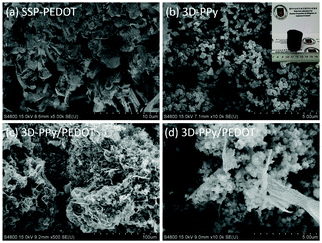
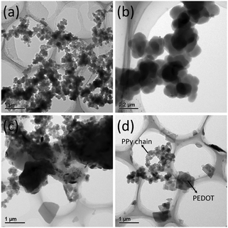
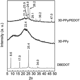
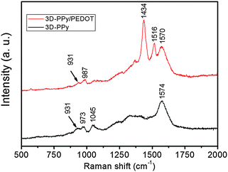
As shown in Fig. 1a, SSP-PEDOT was formed from two dimensional (2D) micron scale sheet-like structures. Fig. 1b shows that pure 3D-PPy was formed from small PPy platelets. In the TEM images, it can be clearly seen that these PPy platelets grew into a chainlike structure (Fig. 2a), and their sizes were around 200 nm. Fig. 1c shows that both flexible 2D sheets and 3D chainlike structures were found in the 3D-PPy/PEDOT composite. The 2D sheets with dimensions of several micrometers were presumed to be SSP-PEDOT, while the 3D chainlike structures were evidently 3D-PPy (Fig. 1d). With the TEM images of 3D-PPy/PEDOT, we can find that SSP-PEDOT with a larger size was connected via PPy chains (Fig. 2c and d).XRD was employed to investigate the crystal structures of DBEDOT, 3D-PPy and 3D-PPy/PEDOT, and the spectra are presented in Fig. 3. Strong signals were observed at 8.6° (200), 17.0° (400), 25.4° (600) and 34.0° (800) from DBEDOT, which was highly similar to its simulated XRD pattern with a strong preferred orientation (Fig. S1, ESI†). It can be inferred that 3D-PPy has an amorphous structure since the broad XRD pattern is around 21.8°. The composite of 3D-PPy/PEDOT also exhibits the amorphous signal from 3D-PPy, however the peaks at 26.2°, 29.1°, 36.2° and 47.0° obviously do not belong to the starting DBEDOT. The Raman spectra of 3D-PPy and 3D-PPy/PEDOT are shown in Fig. 4. In 3D-PPy, the peaks at 931 and 973 cm−1 were attributed to the quinonoid bipolaron and polaron structure of PPy, respectively.48,49 The peak at 1574 cm−1 was owing to the C![[double bond, length as m-dash]](https://www.rsc.org/images/entities/char_e001.gif) C backbone stretching and it could be used to evaluate the conjugation length of conjugated polymer chains.50 For the 3D-PPy/PEDOT composite, two new peaks were found at 1434 and 1516 cm−1, and they were attributed to the C
C backbone stretching and it could be used to evaluate the conjugation length of conjugated polymer chains.50 For the 3D-PPy/PEDOT composite, two new peaks were found at 1434 and 1516 cm−1, and they were attributed to the C![[double bond, length as m-dash]](https://www.rsc.org/images/entities/char_e001.gif) C stretching in PEDOT.37 All of the above analyses confirm the successful formation of the 3D-PPy/PEDOT composite.
C stretching in PEDOT.37 All of the above analyses confirm the successful formation of the 3D-PPy/PEDOT composite.
Fig. 5 and 6 show the complex permittivity (εr) of the as-fabricated 3D-PPy/PEDOT–wax composites through coaxial wire analysis. Based on the Debye theory, the real part (ε′) and imaginary part (ε′′) of the permittivity can be described as6
 | (1) |
 | (2) |
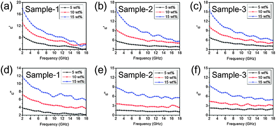 | ||
| Fig. 5 Real part (a–c) and imaginary part (d–f) of the relative complex permittivities of sample-1, sample-2 and sample-3. All the samples are mixed with wax. | ||
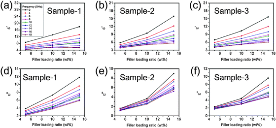 | ||
| Fig. 6 Filler loading ratio vs. real part (a–c) and imaginary part (d–f) of the relative complex permittivities of sample-1, sample-2 and sample-3 under specific frequencies. | ||
Due to the fact that the tested frequency range is from 2–18 GHz, the source-to-shield distance is greater than the free-space wavelength, so the measurements are considered to have been performed under far-field.53 According to the transmission line theory,54 the input impedance (Zin) on the interface can be expressed as
 | (3) |
Based on the model of the metal backplane, the reflection loss (RL) of a sample is determined by Z0 and Zin according to the following equation
 | (4) |
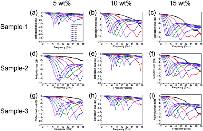
The optimal thicknesses of each sample were taken into account for the higher EA performance and the results are shown in Fig. 7. When the thickness of the absorber increases, the frequency of RLmax gradually shifts toward a lower frequency. This can be explained by the fact that the formation of quarter-wavelength attenuation requires the absorbing thickness to meet the phase matching conditions.6Fig. 7a suggests that sample-1 exhibits an effective EA bandwidth of 6.24 GHz (11.76 to 18 GHz) at a thickness of 2.5 mm. Fig. 7e shows that the effective EA bandwidth of sample-2 is 5.88 GHz at a thickness of 2.5 mm. In sample-3, when the filler loading ratio is 10 wt%, the composite exhibits an effective EA bandwidth of 6.28 GHz at a thickness of 2.5 mm (Fig. 7h). In Table 1, we summarized some outstanding electromagnetic absorbing ICP hybrid composites which have been published in recent years. It can be clearly found that 3D-PPy/PEDOT based composites have the potential to be ideal absorber materials.
| Filler | Matrix | Loading ratio (wt%) | Thickness (mm) | Frequency range (GHz) (RL below −10 dB) | Effective bandwidth (GHz) (RL below −10 dB) | Ref. |
|---|---|---|---|---|---|---|
| Sample-1 | Wax | 5 | 2.5 | 11.76–18.00 | 6.24 | This work |
| Sample-2 | Wax | 10 | 2.5 | 11.00–16.88 | 5.88 | This work |
| Sample-3 | Wax | 10 | 2.5 | 10.76–17.04 | 6.28 | This work |
| 3D-PPy | Wax | 7 | 2.5 | 10.72–16.92 | 6.20 | 52 (2015) |
| 3D-PPy/RGO | Wax | 10 | 3.0 | 10.20–16.96 | 6.76 | 6 (2015) |
| SSP-PEDOT | Wax | 50 | 2.0 | 10.00–15.90 | 5.90 | 55 (2014) |
| 3D-RGO/PEDOT | Wax | 10 | 2.0 | 11.50–16.50 | 5.00 | 35 (2014) |
| PANi/RGO | Wax | 10 | 3.5 | 8.20–13.50 | 5.30 | 34 (2014) |
| PEDOT/RGO/Co3O4 | Wax | 50 | 2.0 | 9.40–12.50 | 3.10 | 37 (2013) |
| Z-BCF/SiO2/PPy | Wax | 33.3 | 2.0 | 12.94–18.00 | 5.06 | 56 (2014) |
4. Conclusions
In summary, a 3D-PPy/PEDOT composite was prepared and its EA performance was investigated for the first time. The 3D-PPy/PEDOT composite consists of chain like structures which are formed by nano PPy platelets and a micron scale PEDOT sheet. 3D-PPy/PEDOT exhibited superior EA performance with a high efficiency and broad bandwidth at a thin thickness and low filler loading. A composite only consisting of 5 wt% 3D-PPy/PEDOT in a wax matrix exhibited an effective EA bandwidth (deeper than −10 dB) of 6.24 GHz at a thickness of 2.5 mm. Furthermore, the highest effective EA bandwidth of 6.28 GHz can be reached when the filler loading ratio of 3D-PPy/PEDOT is 10 wt%. It was demonstrated that this composite material has the potential to absorb electromagnetic pollution.Author contributions
The manuscript was written through the contributions of all authors. All authors have given their approval for the submission of the final version of the manuscript.Conflicts of interest
The authors declare no competing financial interest.Acknowledgements
This work was financially supported by the National Natural Science Foundation of China (51403236), the Opening Project of State Key Laboratory of Disaster Prevention & Mitigation of Explosion & Impact (DPMEIKF201310) and Postdoctoral Science Foundation of China (2015M570452).References
- R. Santini, P. Santini, J. M. Le Ruz, M. Danze and M. Seigne, Electromagn. Biol. Med., 2003, 22, 41 CrossRef
.
- E. A. Navarro, J. Segura, M. Portolés and C. G. Perretta, Electromagn. Biol. Med., 2003, 22, 161 CrossRef
.
- G. Abdel-Rassoul, M. A. Salem, A. Michael, F. Farahat, M. El-Batanuny and E. Salem, Neurotoxicology, 2007, 28, 434 CrossRef CAS PubMed
.
- I. N. Magras and T. D. Xenos, Bioelectromagnetics, 1997, 18, 445 CrossRef
.
- A. Balmori, Pathophysiology, 2009, 16, 191 CrossRef PubMed
.
- F. Wu, A. Xie, M. Sun, Y. Wang and M. Wang, J. Mater. Chem. A, 2015, 3, 14358 CAS
.
- H. R. Tantawy, D. E. Aston, J. R. Smith and J. L. Young, ACS Appl. Mater. Interfaces, 2013, 5, 4648 CAS
.
- M. Cao, X. Shi, X. Fang, H. Jin, Z. Hou, W. Zhou and Y. Chen, Appl. Phys. Lett., 2007, 91, 203110 CrossRef
.
- G. Wang, Y. Wu, X. Zhang, Y. Li, L. Guo and M. Cao, J. Mater. Chem. A, 2014, 2, 8644 CAS
.
- S. He, G. Wang, C. Lu, B. Wen, H. Liu, L. Guo and M. Cao, J. Mater. Chem. A, 2013, 1, 4685 CAS
.
- Y. Wei, G. Wang, Y. Wu, Y. Yue, J. Wu, C. Lu and L. Guo, J. Mater. Chem. A, 2014, 2, 5516 CAS
.
- M. Zhou, X. Zhang, J. Wei, S. Zhao, L. Wang and B. Feng, J. Phys. Chem. C, 2011, 115, 1398 CAS
.
- G. Wang, S. He, X. Luo, B. Wen, M. Lu, L. Guo and M. Cao, RSC Adv., 2013, 3, 18009 RSC
.
- X. Luo, G. Wang, H. Guo, X. Zhang, W. Cao, Y. Wei, L. Guo and M. Cao, ChemPlusChem, 2014, 79, 1089 CrossRef CAS
.
- G. Sun, B. Dong, M. Cao, B. Wei and C. Hu, Chem. Mater., 2011, 23, 1587 CrossRef CAS
.
- H. Yang, M. Cao, Y. Li, Z. Shi, Z. Hou, X. Fang, H. Jin, W. Wang and J. Yuan, Adv. Opt. Mater., 2014, 2, 214 CrossRef
.
- H. Yang, W. Cao, D. Zhang, T. Su, H. Shi, W. Wang, J. Yuan and M. Cao, ACS Appl. Mater. Interfaces, 2015, 7, 7073 CAS
.
- C. Zhu, M. Zhang, Y. Qiao, G. Xiao, F. Zhang and Y. Chen, J. Phys. Chem. C, 2010, 114, 16229 CAS
.
- X. Shi, M. Cao, J. Yuan, Q. Zhao, Y. Kang, X. Fang and Y. Chen, Appl. Phys. Lett., 2008, 93, 183118 CrossRef
.
- J. Zheng, Z. Yu, G. Ji, X. Lin, H. Lv and Y. Du, J. Alloys Compd., 2014, 602, 8 CrossRef CAS
.
- B. Zhao, G. Shao, B. Fan, W. Zhao and R. Zhang, Phys. Chem. Chem. Phys., 2015, 17, 2531 RSC
.
- B. Wen, M. Cao, Z. Hou, W. Song, L. Zhang, M. Lu, H. Jin, X. Fang, W. Wang and J. Yuan, Carbon, 2013, 65, 124 CrossRef CAS
.
- Y. Qing, X. Wang, Y. Zhou, Z. Huang, F. Luo and W. Zhou, Compos. Sci. Technol., 2014, 102, 161 CrossRef CAS
.
- Y. Chen, Z. Huang, M. Lu, W. Cao, J. Yuan, D. Zhang and M. Cao, J. Mater. Chem. A, 2015, 3, 12621 CAS
.
- M. Lu, M. Cao, Y. Chen, W. Cao, J. Liu, H. Shi, D. Zhang, W. Wang and J. Yuan, ACS Appl. Mater. Interfaces, 2015, 7, 19408 CAS
.
- W. Song, M. Cao, L. Fan, M. Lu, Y. Li, C. Wang and H. Ju, Carbon, 2014, 77, 130 CrossRef CAS
.
- Y. Huang, Y. Wang, Z. Li, Z. Yang, C. Shen and C. He, J. Phys. Chem. C, 2014, 118, 26027 CAS
.
- D. Micheli, A. Vricella, R. Pastore and M. Marchetti, Carbon, 2014, 77, 756 CrossRef CAS
.
- B. Wu, H. M. Tuncer, A. Katsounaros, W. Wu, M. T. Cole, K. Ying, L. Zhang, W. I. Milne and Y. Hao, Carbon, 2014, 77, 814 CrossRef CAS
.
- X. J. Zhang, G. S. Wang, W. Q. Cao, Y. Z. Wei, M. S. Cao and L. Guo, RSC Adv., 2014, 4, 19594 RSC
.
- B. Wen, X. Wang, W. Cao, H. Shi, M. Lu, G. Wang, H. Jin, W. Wang, J. Yuan and M. Cao, Nanoscale, 2014, 6, 5754 RSC
.
- B. Wen, M. Cao, M. Lu, W. Cao, H. Shi, J. Liu, X. Wang, H. Jin, X. Fang, W. Wang and J. Yuan, Adv. Mater., 2014, 26, 3484 CrossRef CAS PubMed
.
- M. Cao, X. Wang, W. Cao and J. Yuan, J. Mater. Chem. C, 2015, 3, 6589 RSC
.
- X. Chen, F. Meng, Z. Zhou, X. Tian, L. Shan, S. Zhu, X. Xu, M. Jiang, L. Wang, D. Hui, Y. Wang, J. Lu and J. Guo, Nanoscale, 2014, 6, 8140 RSC
.
- F. Wu, Y. Wang and M. Wang, RSC Adv., 2014, 4, 49780 RSC
.
- P. Liu, Y. Huang and X. Sun, RSC Adv., 2013, 3, 19033 RSC
.
- P. Liu, Y. Huang, L. Wang and W. Zhang, ACS Appl. Mater. Interfaces, 2013, 5, 12355 CAS
.
- Y. Li, D. Chen, X. Liu, Y. Zhou, Q. Zhuang, R. Cai and K. Zhang, Compos. Sci. Technol., 2014, 100, 212 CrossRef CAS
.
- P. Liu, Y. Huang and X. Zhang, Mater. Lett., 2014, 136, 298 CrossRef CAS
.
- F. Guo, R. Li, J. Xu, L. Zou and S. Gan, Colloid Polym. Sci., 2014, 292, 2173 CAS
.
- J. Shen, K. Chen, L. Li, W. Wang and Y. Jin, J. Alloys Compd., 2014, 615, 488 CrossRef CAS
.
- Y. Wang, Y. Huang and J. Ding, Synth. Met., 2014, 196, 125 CrossRef CAS
.
- M. Wang, G. Ji, B. Zhang, D. Tang, Y. Yang and Y. Du, J. Magn. Magn. Mater., 2015, 377, 52 CrossRef CAS
.
- Y. Gao and Z. Tang, Small, 2011, 7, 2133 CrossRef CAS PubMed
.
- Y. Lu, W. He, T. Cao, H. Guo, Y. Zhang, Q. Li, Z. Shao, Y. Cui and X. Zhang, Sci. Rep., 2014, 4, 5792 Search PubMed
.
- A. M. Nicolson and G. F. Ross, IEEE Trans. Instrum. Meas., 1970, 4, 377 CrossRef
.
- W. B. Weir, Proc. IEEE, 1974, 62, 33 CrossRef
.
- S. Demoustier-Champagne and P. Stavaux, Chem. Mater., 1999, 11, 829 CrossRef CAS
.
- J. Zhong, S. Gao, G. Xue and B. Wang, Macromolecules, 2015, 48, 1592 CrossRef CAS
.
- Y. Liu and C. Tsai, Chem. Mater., 2003, 15, 7 Search PubMed
.
- H. Meng, D. F. Perepichka, M. Bendikov, F. Wudl, G. Z. Pan, W. J. Yu, W. J. Dong and S. Brown, J. Am. Chem. Soc., 2003, 125, 15151 CrossRef CAS PubMed
.
- A. Xie, F. Wu, M. Sun, X. Dai, Z. Xu, Y. Qiu, Y. Wang and M. Wang, Appl. Phys. Lett., 2015, 106, 222902 CrossRef
.
- N. F. Colaneri and L. W. Shacklette, IEEE Trans. Instrum. Meas., 1992, 41, 291 CrossRef
.
- Y. Naito and K. Suetake, IEEE Trans. Microwave Theory Tech., 1971, 19, 65 CrossRef
.
- F. Wu, Z. Xu, Y. Wang and M. Wang, RSC Adv., 2014, 4, 38797 RSC
.
- J. Shen, K. Chen, L. Li, W. Wang and Y. Jin, J. Alloys Compd., 2014, 615, 488–495 CrossRef CAS
.
Footnote |
| † Electronic supplementary information (ESI) available. See DOI: 10.1039/c5tc02887f |
| This journal is © The Royal Society of Chemistry 2016 |

