Zr and Y co-doped perovskite as a stable, high performance cathode for solid oxide fuel cells operating below 500 °C†
Chuancheng
Duan
a,
David
Hook
b,
Yachao
Chen
a,
Jianhua
Tong
 *c and
Ryan
O'Hayre
*a
aDepartment of Metallurgical and Materials Engineering, Colorado School of Mines, 1500 Illinois St. Golden, CO 80401, USA. E-mail: rohayre@mines.edu
bCoorsTek, 600 9th St., Golden, CO 80401, USA
cDepartment of Materials Science and Engineering, Clemson University, Clemson, South Carolina 29634, USA. E-mail: jianhut@clemson.edu
First published on 7th October 2016
Abstract
Zr and Y co-doped perovskite BaCo0.4Fe0.4Zr0.1Y0.1O3−δ (BCFZY0.1) was recently developed as a promising new cathode for protonic ceramic fuel cells (PCFCs). Here, it is applied for the first time as a cathode for low-temperature solid oxide fuel cells (LT-SOFCs). It exhibits large lattice parameters, high oxygen reduction reaction (ORR) activity, exceptional low-temperature performance, long-term stability, and excellent chemical compatability with ceria-based SOFC electrolytes. When BCFZY0.1 is used as the cathode in Ce0.8Gd0.2O2−δ (GDC20)-based SOFCs, it enables a peak power density of 0.97 W cm−2 at 500 °C with 2500 hours stable performance and complete recoverability without any degradation after more than 80 fast thermal ramping cycles. Even at 350 °C, peak power density reaches 0.13 W cm−2. It also shows good H2O and CO2 tolerance.
Broader contextSolid-oxide fuel cells (SOFCs) enable high-efficiency conversion of various fuels, including hydrogen and hydrocarbon fuels, into electricity. However, most current SOFCs operate at relatively high temperatures (>700 °C), which necessitates the use expensive stack and balance-of-plant components and can lead to undesirably high degradation rates. Significant research is therefore being devoted to developing new SOFC materials and devices that can operate with high performance at lower temperatures (e.g. <500 °C) while also showing excellent durability. The development of new cathode materials is particularly crucial to lowering fuel cell operating temperatures. Here, we applied BaCo0.4Fe0.4Zr0.1Y0.1O3−δ (BCFZY0.1) for the first time as a cathode for low-temperature SOFCs, achieving high power densities below 500 °C, 2500 hours stable performance, excellent thermal cycling stability and good CO2/H2O tolerance. While originally developed for protonic-ceramic fuel cells, these results show that BCFZY0.1 is a highly promising new cathode for SOFCs as well. |
1. Introduction
Solid oxide fuel cells (SOFCs) enable highly-efficient electricity generation from a wide variety of chemical fuels.1,2 However, they generally operate at high temperatures (typically 700–1000 °C), which leads to expensive fuel cell components, high balance of plant cost, slow start-up and shut-down, poor cycling capability, and poor durability. Decreasing SOFC operating temperature is therefore a central goal of current fuel cell research.3 Both ohmic (electrolyte) and kinetic (electrode polarization) losses tend to increase significantly with decreasing temperature, which must be addressed in order to enable SOFC operation at low temperatures (≤500 °C). Ohmic loss is primarily addressed by decreasing electrolyte thickness4 and/or by developing new electrolyte materials with increased low-temperature ionic conductivity.5 Ultrathin-film deposition technologies (such as pulsed-laser deposition) have been used to fabricate functional SOFCs with electrolytes ≤100 nm,6 enabling SOFC operation at <600 °C. Meanwhile, electrode losses, especially cathode losses (which typically dominate the electrode performance at temperature lower than 500 °C), can be minimized by optimizing the electrode microstructure and increasing the cathode ORR activity.7,8 However, most known SOFC cathode materials possess activation energies of 100–200 kJ mol−1, meaning that electrode polarization losses increase steeply with decreasing temperature. For example, the activation energy of the well-known cathode material Ba0.5Sr0.5Co0.8Fe0.2O3−δ (BSCF) is ∼120 kJ mol−1.9 This results in a 10× increase in electrode polarization resistance with just a 100 °C decrease in operating temperature (from 600 °C to 500 °C). Thus, high-activity cathode materials with lower activation energy are critically needed if SOFC operating temperature is to be reduced below 500 °C.A number of prospective cathode materials have been applied to LT-SOFCs including the previously mentioned BSCF9 as well as La0.8Sr0.2MnO3−δ–ZrxY1−xO2−δ (LSM–YSZ) composites,10 La0.6Sr0.4Co0.8Fe0.2O3−δ (LSCF),11 and LnBaCo2O5+δ (LBCO).12 LSM–YSZ composite cathodes are among the most widely applied options for SOFCs. They were originally developed for high-temperature SOFCs which usually operate above 800 °C. Because LSM is a poor ionic conductor, especially at low temperatures, ORR activity is restricted to the YSZ/LSM/gas triple-phase boundary (TPB) and performance drops sharply at low temperatures. Although ORR activity can be significantly enhanced by nanostructuring approaches, such as infiltrating LSM nanoparticles onto a porous YSZ framework,8 cathode performance below 600 °C is still very poor. To address the issues associated with LSM–YSZ composite cathodes, alternative cathode materials such as BSCF are increasingly studied. In recent studies,9 BSCF has been shown to enable high fuel cell performance at 600 °C (peak power density as high as ∼1 W cm−2). However, performance drops steeply with further decreases in temperature (e.g. the best reported peak power density at 400 °C is only ∼95 mW cm−2). SOFCs based on thin GDC electrolytes with core/shell fibre-structured BSCF–GDC cathodes were recently demonstrated by Yong Gun Shui et al.7 with impressive power densities as high as 2 W cm−2 at 550 °C. Again, however, the performance drops sharply with further decreases in operating temperature (e.g. dropping to 0.84 W cm−2 at 450 °C) because of the high activation energy of the cathode and low ORR activity at low temperatures. In addition, the cathode shows rapid degradation (5.6% loss in power density within 250 hours) and the core/shell nanostructure approach may be challenging to scale commercially. As an alternative but perhaps costly approach, Prinz et al.13 have demonstrated micro-SOFCs using thin-film deposition methods with performance as high as 1.3 W cm−2 at 450 °C using expensive nanostructured Pt cathodes.
For commercial application, SOFCs must demonstrate excellent long-term durability and thermal robustness in addition to good performance. Poor thermal cycling stability is usually caused by poor thermal shock resistance due to mismatches in thermal expansion characteristics between the various components of the MEA and/or stress-induced delamination between electrode and electrolyte. In most SOFCs, the cathode is usually sintered separately and at lower temperature compared with anode and electrolyte in order to get a porous structure with high surface area. However, this can lead to a weak electrode/electrolyte interface that is susceptible to delamination. Despite the crucial importance of thermal-cycle stability, few studies in the literature have examined rapid thermal cycling in SOFCs. As a notable exception, Kun Joong Kim et al. recently demonstrated good stability after 10 quick thermal cycles for micro SOFCs fabricated on porous stainless steel.14 Lower-temperature SOFC operation should benefit thermal-cycle stability since thermal gradients and transients are generally reduced.
Here, we investigate BaCo0.4Fe0.4Zr0.1Y0.1O3−δ (BCFZY0.1) as a new cathode for low-temperature solid oxide fuel cells (LT-SOFCs). Originally developed for protonic ceramic fuel cells (PCFCs) we show that that BCFZY0.1 enables excellent LT-SOFC performance with >2500 hours stable operation in Ce0.8Gd0.2O2−δ (GDC20)-based SOFC single cells. The combination of excellent performance, great stability and high ORR activity at low temperatures suggests BCFZY0.1 is a promising new cathode for LT-SOFCs.
2. Experimental
2.1 Materials synthesis and cell fabrication
BCFZY0.1 cathode powders were synthesized using a previously developed sol–gel method.15 The required amounts (based on desired cathode stoichiometry) of Ba(NO3)2 (Alfa Aesar), Co(NO3)2·6H2O (Alfa Aesar), Fe(NO3)3·9H2O (Alfa Aesar), ZrO(NO3)2 35 wt% in dilute nitric acid (Sigma Aldrich), Y(NO3)3·6H2O (Alfa Aesar), EDTA (Alfa Aesar) and citric acids (Alfa Aesar) were dissolved in ammonium hydroxide while heating and stirring continuously. A dark purple gel was obtained as excess water was gradually evaporated from the solution. The gel was put into a drying oven at 150 °C for 24 hours to get a dark porous charcoal. The charcoal was ball-milled with 1-butanol as solvent for 48 hours. Then, the powder was dried at 100 °C for 12 hours. The powder was then calcined at 600 °C for 5 hours followed by ball-milling again with 1-butanol for 48 hours and dried at 100 °C for 12 hours. BSCF powders were synthesized by the same method.In order to be compared with BSCF, Sm0.2Ce0.8O2+δ (SDC20, FuelCellMaterials, SDC20-TC) was chosen as the electrolyte. SDC20 precursor powder was dry-pressed under 375 MPa for 1.5 minutes in a 19 mm diameter die to prepare the symmetric cell electrolyte green pellets (pellet thickness = 1.5 mm). Then, the pellets were sintered at 1450 °C for 5 hours. Pellet thickness was reduced to 1 mm by grinding both sides of the pellets. Cathode paste was prepared by mixing 5 g of the respective powders with 1 g dispersant (20 wt% solsperse 28![[thin space (1/6-em)]](https://www.rsc.org/images/entities/char_2009.gif) 000 (Lubrizol) dissolved in terpinol), and 0.3 g binder (5 wt% V-006 (Heraeus) dissolved in terpinol). Cathode paste was printed on both sides of the electrolyte pellet followed by annealing at 900 °C for 5 hours. Effective cathode area for the symmetric cell studies was 0.2 cm2. Cathode thickness was 20 μm.
000 (Lubrizol) dissolved in terpinol), and 0.3 g binder (5 wt% V-006 (Heraeus) dissolved in terpinol). Cathode paste was printed on both sides of the electrolyte pellet followed by annealing at 900 °C for 5 hours. Effective cathode area for the symmetric cell studies was 0.2 cm2. Cathode thickness was 20 μm.
The anode precursor powder (FuelCellMaterials.com, NiO/GDC10 (Ce0.9Gd0.1O2−δ), lot#: 279-008, surface area: 6.2 m2 g−1) was dry-pressed under 375 MPa for 1.5 minutes in a 19 mm diameter die to prepare the anode green pellets (thickness ∼1.5 mm). GDC20 powder (FuelCellMaterials.com, GDC20-M, lot#: 274-069, surface area: 201 m2 g−1) was used as the electrolyte precursor. 15 g GDC20 powder was ball-milled with 0.4 mL solsperse 28![[thin space (1/6-em)]](https://www.rsc.org/images/entities/char_2009.gif) 000 (Lubrizol) as dispersant, 2 mL di-n-butyphthalate (Sigma Aldrich) as a plasticiser and 150 mL IPA as solvent for 24 hours. The green anode pellets were dipped into the electrolyte slurry for 3 seconds and then placed into a drying oven (T = 100 °C) for 1 hour. This process was repeated 4 times to obtain sufficient electrolyte thickness. After drying, cells were co-fired at 1450 °C for 5 hours with cooling and heating rates of 1.5 °C min−1. After firing, the electrolyte was removed from one side by grinding. The thickness of the anode for cell 1 was reduced to ∼1.2 mm by grinding. For cells 2 and 3, the anode thickness was reduced to ∼0.4 mm. For all three cells, the cathode was subsequently printed onto the electrolyte-coated side followed by sintering at 900 °C for 5 hours.
000 (Lubrizol) as dispersant, 2 mL di-n-butyphthalate (Sigma Aldrich) as a plasticiser and 150 mL IPA as solvent for 24 hours. The green anode pellets were dipped into the electrolyte slurry for 3 seconds and then placed into a drying oven (T = 100 °C) for 1 hour. This process was repeated 4 times to obtain sufficient electrolyte thickness. After drying, cells were co-fired at 1450 °C for 5 hours with cooling and heating rates of 1.5 °C min−1. After firing, the electrolyte was removed from one side by grinding. The thickness of the anode for cell 1 was reduced to ∼1.2 mm by grinding. For cells 2 and 3, the anode thickness was reduced to ∼0.4 mm. For all three cells, the cathode was subsequently printed onto the electrolyte-coated side followed by sintering at 900 °C for 5 hours.
2.2 Materials characterization
Cell morphologies and microstructures were examined by Field Emission Scanning Electron Microscopy (FESEM) using a JEOL JSM7000F. Room temperature X-ray diffraction (XRD) analyses of powders were performed using a Philips X’Pert Pro MPD diffractometer (PANalytical, Almelo, the Netherlands) with Cu-Kα radiation, tube voltage 45 kV, and tube current 40 mA. Intensities were collected in the 2θ range between with a step size of 0.008° and a measuring time of 5 s at each step. High-temperature X-ray diffraction (HT-XRD) analyses of powders were performed using a Bruker D8 Discover TWIN/TWIN diffractometer with a vertical goniometer (radius is 280 mm), Cu-Kα radiation, tube voltage 45 kV, and tube current 40 mA. In situ heating was accomplished with an Anton Paar HTK 2000N hot stage which utilizes a 0.5 mm Pt stripe heater. Intensities were collected both on heating and on cooling in the 2θ range between 12 and 90 with a step size of 0.025° and a measuring time of 0.75 s at each step. The heating rate was 5 °C min−1, with a 5 min hold at each temperature before scan initiation. The cooling rate was 15 °C min−1 with a 5 minutes hold before each scan.Environmental-controlled HT-XRD was performed using the same instrument to study the CO2 tolerance of BCFZY0.1. A scan was first acquired at room temperature in ultra high purity (UHP) air. Under UHP air, the sample was heated to 500 °C and a second scan was run. Another 8 scans were performed at the same temperature after switching from UHP Air to 5%CO2 + 21%O2 + 74%N2 for 20 minutes. Then the atmosphere was switched back to UHP air, 16 scans were done after waiting for 20 minutes. For both gas conditions, a flow rate of 20 mL min−1 was used.
2.3 Symmetric cell and fuel cell evaluation
Gold paste was printed on both sides of symmetric cells as a current collector. Electrochemical impedance spectroscopy (EIS) was performed with a Gamry reference 600 using a signal amplitude of 10 mV under dry air (unhumidified 21%O2 + 79%N2, General Air) atmosphere and open circuit voltage (OCV) conditions in the frequency range of 0.01–106 Hz. EIS was conducted at 300–600 °C. For fuel cell testing, gold paste was applied as a current collector on both the anode and cathode electrodes. Single cells were sealed on alumina tubes by glass powder. I–V polarization curves were measured with 150 mL min−1 air and 50 mL min−1 hydrogen as oxidant and fuel respectively by Gamry reference 3000 over a range of temperatures from 350–500 °C.3. Results and discussion
3.1 Low activation energy and good stability
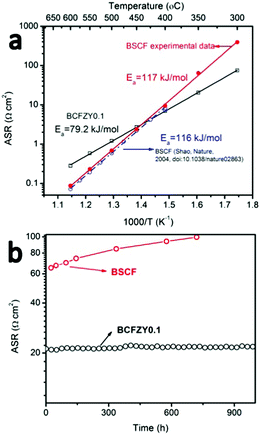
BCFZY0.1 was originally developed for PCFCs as it possesses mixed oxygen ion, proton and electron conductivity and high ORR activity at low temperatures.16 However, we hypothesize that it should also be an excellent cathode for LT-SOFCs because it possesses a much lower activation energy (∼80 kJ mol−1) than most other cathode alternatives (Fig. 1a). When applied to PCFCs, BCFZY0.1 has demonstrated excellent long-term stability (≥1400 hours without loss in performance) and good low-temperature performance (>450 mW cm−2 at 500 °C).Fig. 1a compares the polarization resistance of BCFZY0.1 (measured by two-probe electrode impedance using a BCFZY0.1|SDC20|BCFZY0.1 symmetric cell) against the well-known SOFC cathode material BSCF (measured by two-probe electrode impedance using a BSCF|SDC20|BSCF symmetric cell). Both symmetric cells used a 1 mm thick electrolyte pellet with 20 μm thick symmetric cathodes. Morphological comparison of BCFZY0.1 and BSCF cathodes before testing (Fig. S1, ESI†) shows ∼3× smaller particle size for BCFZY0.1, consistent with its more refractory nature. This property facilitates the fabrication of a stable cathode nanostructure using traditional ceramic processing methods, which is difficult to accomplish with BSCF. As shown in Fig. 1a, BCFZY0.1 shows much lower activation energy (79.2 kJ mol−1) than BSCF (117 kJ mol−1). For further comparison, previously reported BSCF symmetric cell polarization data from Shao et al. is also included in the figure. Their BSCF polarization resistance and activation energy (116 kJ mol−1) closely match our results. Because of the significantly different activation energies, the performance of the two cathodes shows a crossover with temperature: at high temperatures, BCFZY0.1 shows higher area-specific resistance (ASR) than BSCF, while at lower temperatures (<450 °C) BCFZY0.1 shows lower ASR. We note that absolute ASR values depend strongly on cathode surface area and microstructure, and so the crossover temperature will change depending on cathode morphology. In general, however, BCFZY0.1 will be favoured at lower temperatures due to its lower activation energy.
BCFZY0.1 also shows promising long-term stability, as shown in Fig. 1b which compares the polarization resistance of BCFZY0.1 and BSCF at 350 °C in dry air. BCFZY0.1 maintains stable performance after 1000 hours of testing while the resistance of BSCF increases from 65.0 to 99.7 Ω cm2 after just 720 hours. Low-temperature instability is a widely noted issue in oxygen permeation membranes based on BSCF. BSCF instability is attributed deleterious phase transformations from the cubic to the hexagonal and/or lamellar trigonal phases at temperatures below 850 °C, particularly at grain boundaries.17 Indeed, post-mortem SEM analysis of our BSCF symmetric cell indicates that second phase impurities formed on the porous cathode surface after the 720 hours testing of durability at 350 °C (Fig. S2a and b, ESI†). There is obvious grain coarsening of BSCF after 720 hours testing while the morphology of BCFZY0.1 before and after 1000 hours testing does not change. Comparing BSCF and BCFZY0.1, we hypothesize that partial substitution of Co3+/Co4+ by larger Zr4+ and Y3+ cations with constant oxidation state helps improve both the ORR activity and phase stability.
3.2 Influence of Co and Y doping on phase structure and stability of BCFZ, BCFZY0.1 and BSCF
Phase structure and stability of BSCF, BCFZ and BCFZY0.1 were studied by in situ HT-XRD. BCFZ was tested in order to study the effect of Y-doping in BCFZY0.1. XRD patterns of these three compositions under air are shown in Fig. S4–S6 (ESI†). The refined unit cell parameter of BSCF at room temperature is 3.9825 Å which is close to the Rietveld refined unit cell parameter (3.9830 Å) reported by Koster and Mertins18 and suggests that our refinement result is reliable. Fig. 2a shows the calculated lattice parameters of the three materials as a function of temperature during heating and cooling. The lattice parameters are identical on heating and cooling, indicating reversible phase behaviour for the three materials across the studied temperature range. The slopes determined by linear fit to the data below 275 °C and above 300 °C are slightly different, which is due to a spin transition,19,20 a typical phenomenon for Co-containing perovskites.21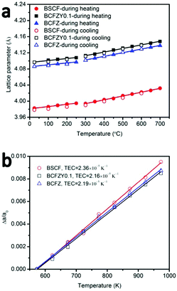 | ||
| Fig. 2 (a) Temperature dependence of lattice parameters of BSCF, BCFZY0.1 and BCFZ, (b) Δa/a0 as a function of temperature (300–700 °C). | ||
Compared to BSCF and other common alternative perovskite cathodes (such as LSCF22), BCFZY0.1 possesses a larger lattice parameter and larger free volume due to the substitution of Co3+/Co4+ by the larger Zr4+ and Y3+ cations.23 In perovskites, larger lattice parameter and free volume is commonly associated with increased oxygen ion mobility and decreased activation energy.24
Thermal expansion coefficients (TECs) in the temperature range 300–700 °C were calculated by fitting the data of Δa/a0 as a function of temperature from 300–700 °C (Fig. 2b). For all three materials, the lattice parameter at 300 °C was used as the reference (a0) to avoid artefacts associated with the Co spin transition. TEC of BSCF in the temperature range of 300–700 °C is 2.36 × 10⁻⁵ K−1 which is close to the data reported by W. Su et al. (2.495 × 10⁻⁵ K−1). BCFZY0.1 shows a little bit lower TEC (2.16 × 10⁻⁵ K−1) than BSCF (2.36 × 10⁻⁵ K−1) and BCFZ (2.19 × 10⁻⁵ K−1) at fuel cell operating temperatures (300–700 °C) which enables higher thermal stability, phase stability and compatibility with the electrolyte.
3.3 Performance and stability of SOFC button cells with BCFZY0.1 as cathode
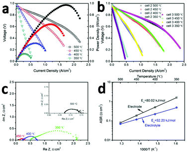
The promising low-temperature ORR activity and stability of BCFZY0.1 highlighted in Fig. 1a, b and 2a, b suggests it should be a promising SOFC cathode. To validate this proposal, several GDC20-based SOFCs were fabricated by pressing GDC10 + NiO anode pellets followed by dip-coating the GDC20 electrolyte and co-firing the anode/electrolyte half-cell at 1500 °C for 5 hours. The BCFZY0.1 cathode was then printed on electrolyte followed by a second annealing step at 900 °C for 5 hours. After annealing, the cathode thickness was 20 μm. Three cells were tested in this work: cell #1, which had a 1.2 mm thick anode, and cells #2 and #3 with much thinner 0.4 mm thick anodes. Cells #2 and #3 were used to verify reproducibility of the observed performance and to enable several follow-up durability and degradation investigations after performance testing.Fig. 3a provides polarization (I–V) and corresponding power density curves (I–P) for cell #2. Comparable data for cell #1 is provided in ESI† (Fig. S7). Compared to cell #1, the thinner anode achieved in cell #2 leads to higher performance. The cell achieves peak power densities of 0.97, 0.64, 0.32 and 0.13 W cm−2 at 500, 450, 400 and 350 °C, respectively. The peak power density at 500 °C is among the highest ever reported for an SOFC at this temperature (Table S1, ESI†). To verify the reproducibility of this performance, cell #3 was fabricated using the same procedure and same final anode thickness as cell #2. As shown by the I–V performance comparison of cells #2 and #3 in Fig. 3b, the two cells yield virtually identical performance.
Fig. S8 (ESI†) shows a representative cross section SEM image of cell #2 after testing. The thickness of the electrolyte is 7 μm. Fig. 3c shows the AC impedance (Nyquist) plots of cell #2 measured in H2/air under open circuit voltage (OCV) at 350–500 °C. Ohmic (ASRohm) and electrode polarization (ASRp) area-specific-resistances can be extracted from the high-frequency real-impedance intercept and the diameter of the impedance arc respectively. These data are shown in an Arrhenius plot in Fig. 3d. The electrode polarization activation energy determined for the full cell in Fig. 3a (80 kJ mol−1) closely matches the value determined previously from the BCFZY0.1 symmetric cell study in Fig. 1a (79 kJ mol−1), and is substantially lower than the activation energy reported for other emerging low-temperature SOFC cathodes such as PrBa0.5Sr0.5Co1.5Fe0.5O5+δ25 or NdBa0.75Ca0.25Co2O5+δ.26 The absolute magnitude of ASRp is also encouraging; it is less than 1 Ω cm2 at 400 °C and less than 0.1 Ω cm2 at 500 °C.
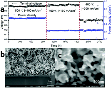
To examine the long-term stability of the cathode, cell #1 was operated under a series of constant load conditions and temperatures for a total of more than 2500 hours without observable performance degradation (Fig. 4a). It is one of the most stable LT-SOFCs reported so far (Table S2, ESI†). Although LT-SOFCs with higher power densities have been reported by several groups as shown in Table S1 (ESI†), the combination of power density and long-term stability is the best reported so far.
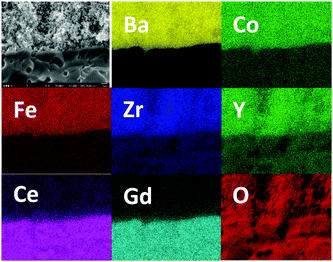
High-magnification SEM cross-section images of the cathode–electrolyte interface (Fig. 4b) and cathode bulk (Fig. 4c) after this 2500 hour durability test show no signs of delamination or interfacial reaction. There are no signs of coarsening or phase separation within the cathode bulk and the cathode morphology of the tested cell appears identical to an unused cell, with an average cathode particle size less than 100 nm. EDX elemental mapping for cell #1 after 2500 hours operation was collected which is shown in Fig. 5. The interface between electrolyte and cathode is very clear and uniform for all 7 elements which indicates there is no element migration and segregation after 2500 hours operation and excellent chemical compatibility of BCFZY0.1 with electrolyte.
3.4 Thermal cycling stability of SOFC button cells with BCFZY0.1 as cathode
Although it is infrequently examined, thermal cycling stability is crucially important for SOFC commercialization, particularly for applications requiring start/stop capability or transient/variable loads. While not all SOFC applications will encounter significant thermal cycling, it can nevertheless also be used as an accelerated stress-test to gain insight into SOFC durability and degradation under aggressive operating conditions or in the case of unplanned shut-down events.Thermal cycling stability is governed by the thermal shock resistance of the MEA components and the magnitude of the thermal stresses that develop between the electrolyte and electrodes. For anode-supported SOFCs, TEC matching between the cathode and the electrolyte is particularly important.
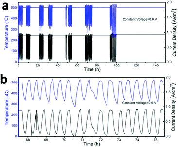
To examine the thermal cycling stability of our LT-SOFC incorporating the new BCFZY0.1 cathode, we subjected cell #2 to 80 rapid thermal cycles while operating at a constant potential of 0.6 V. The clam-shell testing furnace was turned off and manually opened to the ambient in order to subject the cell to as rapid a cooling rate as possible. Using this approach, we achieved cooling rates as high as 18 °C min−1 (Fig. S9, ESI†). Fig. 6a shows the temperature and current density profiles continuously recorded over a period of approximately 5 days, during which time the cell was subjected to 80 rapid thermal cycles. The magnified temperature and current density profiles for several representative thermal cycles (Fig. 6b) show that the cell power output dropped to zero as the cell temperature fell to ∼230 °C, at which point the furnace was closed and turned back on. The cell typically required just 16 minutes to fully recover to its original temperature and performance at 500 °C. Prior to thermal cycling, the initial cell current density was 0.9 A cm−2 at 0.6 V. Between each thermal cycle and upon completion of the full 80 thermal cycles, the cell current density fully recovered to 0.9 A cm−2; this stable performance was maintained for a further 50 hours of operation after completion of the thermal cycling protocol. The excellent thermal cycling stability of this cell confirms the thermomechanical compatibility of the BCFZY0.1 cathode with GDC electrolyte.
3.5 CO2 and H2O tolerance of BCFZY0.1
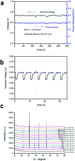
Many Ba-containing perovskites show instabilities in CO2 and/or H2O-containing atmospheres due to the formation of BaCO3 and/or Ba(OH)2 phases,27,28 respectively. For example, BaCeO3 shows strong reactivity in both CO2 and H2O,27–30 which has prevented its widespread use in proton-conducting ceramic fuel cells despite its high proton conductivity. BaZrO3, on the other hand, shows very little reactivity against CO2 or H2O. As BCFZY0.1 is a Ba-based perovskite, preliminary assessment of its stability in CO2 and H2O containing environments is warranted. To study H2O tolerance, the cathode of cell #1 was then supplied with humidified air (5% steam) while operating at j = 0.4 A cm−2 at 500 °C (Fig. 7a). No degradation in performance was noted after more than 300 hours of testing, indicating that BCFZY0.1 is fully stable in humidified air.To study CO2 tolerance, the BCFZY0.1 cathode of cell #3 was subjected to cycling between pure air and air containing 5%CO2 while operating at j = 1.0 A cm−2 at 500 °C (Fig. 7b). Upon exposure to 5%CO2, the cell voltage drops from ∼0.65 V to ∼0.58 V, which we attribute to competitive absorption of CO2vs. oxygen of the surface of the cathode (thereby blocking catalytic surface-sites). In addition, XRD evidence (detailed below) reveals the formation of BaCO3 in the cathode, which may further compromise the ORR kinetics. Nevertheless, upon re-exposure to pure air the cell voltage fully recovers. Reversible voltage recovery is demonstrated for 7 CO2 exposure cycles during 35 hours of continuous cyclic testing which is shown in Fig. 7b. HT-XRD was performed under the same conditions (Fig. 7c). After exposure to 5%CO2, XRD analysis reveals the appearance of a peak at ∼23.9°, indicating the formation of BaCO3. After 2 hours exposure to CO2, the atmosphere was switched back to air. Even after switching back to pure air, however, the BaCO3 peak remained present. These results demonstrate that BaCO3 formation is likely not fully reversible upon re-exposure to air. However, it appears to be sufficiently reversible under fuel cell operating conditions (or sufficiently benign once formed) to preclude permanent degradation.
4. Conclusions
In summary, Zr and Y co-doped perovskite (BCFZY0.1) is a highly promising, active, and stable cathode for low-temperature solid oxide fuel cells (≤500 °C). High ORR activity, low activation energy, and excellent thermal cycling stability strongly suggest that BCFZY0.1 is a potentially intriguing new cathode for commercial SOFC applications.Acknowledgements
This work was supported by Advanced Research Projects Agency-Energy (ARPA-E) for funding under the REBELS program (award DE-AR0000493).Notes and references
-
R. O'Hayre, S.-W. Cha, C. Whitney and F. B. Prinz, Fuel Cell Fundamentals, 2009 Search PubMed
.
- R. J. Gorte, S. Park and J. M. Vohs, Nature, 2000, 404, 265–267 CrossRef PubMed
.
- E. D. Wachsman and K. T. Lee, Science, 2011, 334, 935–939 CrossRef CAS PubMed
.
- J. Will, A. Mitterdorfer, C. Kleinlogel, D. Perednis and L. J. Gauckler, Solid State Ionics, 2000, 131, 79–96 CrossRef CAS
.
- C. Zuo, S. Zha, M. Liu, M. Hatano and M. Uchiyama, Adv. Mater., 2006, 18, 3318–3320 CrossRef CAS
.
- H. Huang, M. Nakamura, P. Su, R. Fasching, Y. Saito and F. B. Prinz, J. Electrochem. Soc., 2007, 154, B20 CrossRef CAS
.
- J. G. Lee, J. H. Park and Y. G. Shul, Nat. Commun., 2014, 5, 4045 CAS
.
- X. Zhang, L. Liu, Z. Zhao, B. Tu, D. Ou, D. Cui, X. Wei, X. Chen and M. Cheng, Nano Lett., 2015, 15, 1703–1709 CrossRef CAS PubMed
.
- Z. Shao and S. M. Haile, Nature, 2004, 431, 170–173 CrossRef CAS PubMed
.
- S. Wang, Solid State Ionics, 1998, 113–115, 291–303 CrossRef CAS
.
- F. Tietz, V. A. C. Haanappel, A. Mai, J. Mertens and D. Stöver, J. Power Sources, 2006, 156, 20–22 CrossRef CAS
.
- K. Zhang, L. Ge, R. Ran, Z. Shao and S. Liu, Acta Mater., 2008, 56, 4876–4889 CrossRef CAS
.
- J. An, Y. B. Kim, J. Park, T. M. Gür and F. B. Prinz, Nano Lett., 2013, 13, 4551–4555 CrossRef CAS PubMed
.
- K. J. Kim, B. H. Park, S. J. Kim, Y. Lee, H. Bae and G. M. Choi, Sci. Rep., 2016, 6, 22443 CrossRef CAS PubMed
.
- M. Shang, J. Tong and R. O'Hayre, Mater. Lett., 2013, 92, 382–385 CrossRef CAS
.
- C. Duan, J. Tong, M. Shang, S. Nikodemski, M. Sanders, S. Ricote, A. Almansoori and R. O'Hayre, Science, 2015, 349, 1321–1326 CrossRef CAS PubMed
.
- Y. Liu, X. Zhu, M. Li, R. P. Ohayre and W. Yang, Nano Lett., 2015, 15, 7678–7683 CrossRef CAS PubMed
.
- H. Koster and F. H. B. Mertins, Powder Diffr., 2003, 18, 56 CrossRef CAS
.
- M. G. Sahini, J. R. Tolchard, K. Wiik and T. Grande, Dalton Trans., 2015, 44, 10875–10881 RSC
.
- B. X. Huang, J. Malzbender, R. W. Steinbrech and L. Singheiser, J. Membr. Sci., 2010, 359, 80–85 CrossRef CAS
.
- X. Chen and T. Grande, Chem. Mater., 2013, 25, 927–934 CrossRef CAS
.
- J. S. Hardy, J. W. Templeton, D. J. Edwards, Z. Lu and J. W. Stevenson, J. Power Sources, 2012, 198, 76–82 CrossRef CAS
.
- H. Wang, C. Tablet, W. Yang and J. Caro, Mater. Lett., 2005, 59, 3750–3755 CrossRef CAS
.
- M. Mogensen, D. Lybye, N. Bonanos, P. V. Hendriksen and F. W. Poulsen, Solid State Ionics, 2004, 174, 279–286 CrossRef CAS
.
- S. Choi, S. Yoo, J. Kim, S. Park, A. Jun, S. Sengodan, J. Kim, J. Shin, H. Y. Jeong, Y. Choi, G. Kim and M. Liu, Sci. Rep., 2013, 3, 305–313 Search PubMed
.
- S. Yoo, A. Jun, Y.-W. Ju, D. Odkhuu, J. Hyodo, H. Y. Jeong, N. Park, J. Shin, T. Ishihara and G. Kim, Angew. Chem., Int. Ed., 2014, 53, 13064–13067 CrossRef CAS PubMed
.
- R. Yan, Q. Wang, G. Chen, W. Huang and K. Xie, Ionics, 2009, 15, 749–752 CrossRef CAS
.
- S. V. Bhide and A. V. Virkar, J. Electrochem. Soc., 1999, 146, 2038 CrossRef CAS
.
- H. Iwahara, Y. Asakura, K. Katahira and M. Tanaka, Solid State Ionics, 2004, 168, 299–310 CrossRef CAS
.
- K. H. Ryu and S. M. Haile, Solid State Ionics, 1999, 125, 355–367 CrossRef CAS
.
Footnote |
| † Electronic supplementary information (ESI) available. See DOI: 10.1039/c6ee01915c |
| This journal is © The Royal Society of Chemistry 2017 |

