Impact of LaF3 and silica shell formation on the crystal, optical and photo-luminescence properties of LaF3:Ce/Tb nanoparticles
Anees A.
Ansari
*a,
Monika
Rai
b and
S. B.
Rai
b
aKing Abdullah Institute for Nanotechnology, King Saud University, Riyadh-11451, Saudi Arabia. E-mail: aneesaansari@gmail.com; Fax: +966-1-4670662; Tel: +966-1-4676838
bDepartment of Physics, Banaras Hindu University, Varansi-221005, India
First published on 25th October 2016
Abstract
LaF3:Ce/Tb and LaF3:Ce/Tb@LaF3 core and core/shell nano-structures were synthesized by the polyol process at low temperature. X-ray diffraction patterns, transmission electron microscopy images, energy dispersive X-ray, FTIR, UV/Vis, and photoluminescence spectra and band gap energy were used to investigate the impact of shell formation on the crystal structure, opto-electronic, photoluminescence and lifetime properties of the core-nanoparticles (core-NPs). The TEM image shows that the as-prepared luminescent core and core/shell/SiO2-NPs consist of polycrystals aggregated with a narrow size distribution, which can be easily dispersed in aqueous and non-aqueous solvents to form a transparent colloidal solution. The TEM image illustrated that the core and core/shell/SiO2 NPs are irregular hexagonals with a mean diameter of 20–35 nm. It is observed that the band gap energy gradually decreased after shell formation which may be due to the decreased crystallinity of the luminescent nanoproducts. The excitation spectra show a characteristic charge transfer transition of Ce3+ 4f–5d(275) and all excitations of Tb3+ 7F6 → 5Dj(7Dj = 1–6) ions, respectively. The excitation, emission and decay time clearly revealed that the luminescence efficiency was greatly enhanced after inert shell formation, whereas after silica surface modification the luminescence efficiency decreased because non-radiative decay is higher in core and core/shell NPs.
1. Introduction
Lanthanide activated luminescent nanoparticles have been the subject of much interest over the last decade due to their exceptional optical and chemical properties i.e. large effective Stokes shifts, high resistance to photo-bleaching, blinking & photochemical degradation and low long-term toxicity, making them highly suitable alternatives to organic dyes and quantum dots in various biological fields.1–6 Owing to these advantages, luminescent lanthanide NPs have evolved as a quickly growing field giving opportunities for new photonic applications, which can be grouped into two main topics.3–6 The first is the development of ultrasensitive markers, for security and in a wide range of bioimaging-related techniques going from intracellular imaging and selective cancer cell detection to thermal sensing.1,6–9 The second topic addresses the fabrication of color panel displays, and light emitting diodes and laser based technology related to different light generation, which is achieved by an adequate balance of blue, green, orange and red light.8–10However, due to non-radiative decay from defects on the surface of the NPs, the luminescence efficiency of nano-structured materials is usually lower than that of the corresponding bulk materials. To reduce these defects, the growth of a crystalline shell of a suitable inorganic material around each nanoparticle to form the core/shell structures has been regarded as an effective strategy to improve luminescence efficiency. Previously, we and some other co-workers have successfully applied this strategy in lanthanide and semiconductor luminescent NPs, in core/shell structure luminescent materials with luminescent lanthanide NPs as cores and inert host compounds as shells.11–17 These core/shell nanostructures doped with lanthanide ions are based on two materials with similar lattice constants to avoid the formation of defects at the core/shell interface. In this structure, the distance between the luminescent lanthanide ions and the surface quenchers is increased, thus reducing the non-radiative pathways and increasing the quantum yield of nanomaterials. Furthermore, this surface functionalization and coating of these luminescent core nanomaterials could increase their impact on fundamental biomedical research and clinical practice.15,16
Compared with the conventional lanthanide luminescent metal oxide nanomaterials, fluorides provide some special advantages, such as high resistivity, excellent thermal & environmental stability and especially low vibrational energies (e.g. LaF3, phonon energy is close to 350 cm−1), which result in the minimization of the quenching of the excited state of the lanthanide ions.6,15,16 Among fluorides, LaF3 is a perfect and most studied ceramic fluorescent host matrix owing to its low vibrational energies, adequate chemical & thermal stability with high quantum yield as well as large solubility, good biocompatibility and expected low toxicity without deleterious effects.18,19 These attractive properties make it a promising fluorescent material for potential applications as a luminescent bio-probe in biomedical sciences.20
Hexagonal and cubic phases are two existing polymorphs of LaF3 NPs depending on the synthesis condition. Recently, it was reported that the efficiency of the lanthanide ion doped LaF3 can be tuned by tuning the crystal phase and the excitation wavelength.18,19 Lanthanide ion doped NPs can be activated either by directly exciting 4fn energy levels or by exciting the charge transfer band.17–20 The opposite parity excited state of the lanthanide ion (charge transfer of fn−1d) and the same parity excited state of the lanthanide ion (direct transition of 4fn) appeared to be important factors for tuning the efficiency of the materials.21,22 In addition to this, some co-doped lanthanide materials greatly enhanced the fluorescence intensity owing to efficient energy transfer between the absorber and emitter ions within the nano-crystal. In the literature, efficient energy transfer between the absorber and emitter ions has been used to prepare the efficient nanomaterials. Previously, some literature reports already described the influence of the crystal phase, the morphology and the wavelength of excitation on the luminescence properties of LaF3. Ce3+ and Tb3+ ions are used for blue and green phosphors, respectively.6,17–22 Zhang et al. reported Ce3+ and Tb3+ co-doped LaF3 NPs grown on the surface of silica microspheres to cater for different bio-applications.20 Liu et al. measured the X-ray luminescence of water soluble LaF3:Ce/Tb NPs and compared their luminescence intensity with that of insulating inorganic LaF3 layer coated core NPs.23 Xie et al. employed a surfactant-free aqueous solution route for the synthesis of Ce3+ and Tb3+ ion doped LaF3 NPs.24 Zhu et al. investigated the photoluminescence properties of silica surface modified La0.45Ce0.45F3:Tb (10 mol% Tb) NPs prepared using a sonochemical method.25 Mi et al. applied the microwave-assisted method to prepare LaF3:Ce3+,Tb3+ NPs for the determination of ascorbic acid via luminescence quenching.26
The work presented here is an effort to investigate the impact of inert LaF3 and amorphous silica shell formation on the polyol process of the synthesized LaF3:Ce3+/Tb3+ core-NPs. X-ray diffraction (XRD), transmission electron microscopy (TEM), electron energy diffraction patterns (EDX), and FTIR, UV/Visible and photoluminescence spectra were utilized to investigate the crystallinity, crystal phase, morphology, and optical and photoluminescence properties of the as-prepared nanoproducts in detail. The as-prepared NPs can be well dispersed in ethanol to form a clear colloidal solution. Here we propose a strategy of how to improve the overall photoluminescence properties as well as colloidal stability in aqueous solvents of the as-prepared LaF3:Ce3+/Tb3+ core-NPs. This core/shell/SiO2 nanoparticle is a promising luminescent material for use as a fluorescent probe in biological labeling and imaging technology.
2. Experimental
2.1. Materials
Lanthanum oxide (99%, BDH chemicals Ltd, England), terbium oxide (99.99%, Alfa Aesar, Germany), cerium nitrate hexahydrate (99%, BDH chemicals Ltd, England), ethanol (E-Merck, Germany), ammonium fluoride, tetraethyl ortho-silicate (TEOS, 99 wt% analytical reagent A.R.), ethylene glycol (EG), C2H5OH, HNO3 and NH4OH were used as the starting materials without any further purification. La(NO3)3·6H2O and Tb(NO3)3·6H2O were prepared by dissolving the corresponding oxides in diluted nitric acid. The de-ionized water was prepared using a Milli-Q system (Millipore, Bedford, MA, USA). All other chemicals used were of reagent grade.2.2. Preparation of LaF3:Ce/Tb NPs
For the preparation of LaF3:Ce3+/Tb3+ NPs (La0.4Ce0.45Tb0.15F3), 0.2 M stock solutions of La(NO3)3·6H2O, Ce(NO3)3·6H2O and Tb(NO3)3·6H2O in de-ionized water were prepared. In brief, 4 ml of La(NO3)3·6H2O, 4.5 ml of Ce(NO3)3·6H2O and 1.5 ml of Tb(NO3)3·6H2O were dissolved together in 50 ml of ethylene glycol. The equivalent molar aqueous solution of NH4F was added dropwise under magnetic stirring to the reaction mixture at 80 °C. The whole solution was kept on a hot plate for homogenous mixing. Later on, this homogenously mixed solution was transferred to a 250 ml round bottom flask fitted with a reflux condenser for 4 h until complete precipitation. Upon cooling to room temperature, the white precipitates then segregated to the bottom. The product was collected via centrifugation, washed with distilled water and absolute ethanol several times, and dried in an oven at 60 °C for 6 h for further characterization.2.3. Preparation of LaF3:Ce/Tb@LaF3 core/shell NPs
For the preparation of LaF3:Ce/Tb@LaF3 core/shell NPs, a similar polyol process was used as discussed above. The as-prepared 0.500 g LaF3:Ce/Tb-NPs were dispersed with the help of ultra-sonication in 10 ml of distilled water. These dispersed NP solutions were mixed in magnetically stirred hot EG dissolved La(NO3)3·6H2O (0.500 g) solution. After thirty minutes, an equivalent molar aqueous solution of NH4F was injected into the foregoing reaction mixture under magnetic stirring at 80 °C. Afterwards this suspension was refluxed at 80 °C for 3 h until complete precipitation occurred. This white precipitate was centrifuged and washed many times with ethanol and distilled water to remove excess un-reacted reactants. The core/shell NPs were collected after centrifugation and allowed to dry at ambient temperature for further characterization.2.4. Preparation of silica coated LaF3:Ce/Tb@LaF3@SiO2 core/shell/SiO2 NPs
The LaF3:Ce/Tb@LaF3@SiO2 core/shell/SiO2 NPs were prepared through a versatile solution sol–gel method as follows.27,28 The synthesized LaF3:Ce/Tb@LaF3 core/shell NPs (50 mg) were well dispersed in a mixed solution of deionized water (50 ml), ethanol (70 ml) and concentrated aqueous ammonia (1.0 ml) in a three-neck round-bottom flask. Afterward, 1.0 ml of tetraethyl orthosilicate (TEOS) was added drop-wise in 2 min, and the reaction was allowed to proceed for 5–6 h under continuous mechanical stirring. After continuous stirring at room temperature, the silica-coated LaF3:Ce/Tb@LaF3 core/shell NPs were separated via centrifugation, washed several times with ethanol and dried at room temperature for further analysis.2.5. Characterization
X-ray diffraction (XRD) was performed at room temperature with the use of a Rigaku X-ray diffractometer equipped with a Ni filter using Cu Kα (λ = 1.54056 Å) radiation as an X-ray source. The size and the morphology of the samples were inspected using a field emission transmission electron microscope (FE-TEM) equipped with an EDX (FETEM, JEM-2100F, JEOL, Japan) operating at an accelerating voltage of 200 kV. EDX analysis was used to confirm the presence of the elements. The samples for TEM were prepared by depositing a drop of a colloidal ethanol solution of the powder sample onto a carbon-coated copper grid. FTIR spectra were recorded on a Perkin-Elmer 580B IR spectrometer using the KBr pellet technique in the range of 4000–400 cm−1. UV/Vis absorption spectra were recorded using a Perkin-Elmer Lambda-40 spectrophotometer in the range of 190–600 nm, with the sample contained in a 1 cm3 stoppered quartz cell of 1 cm path length. The excitation and emission spectra were recorded on a Perkin-Elmer photoluminescence spectrophotometer equipped with a 150 W xenon lamp as the excitation source. All measurements were performed at room temperature.3. Results and discussion
3.1. Phases, crystal structures and morphologies
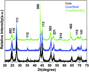
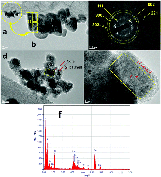
The phase purity, crystalline phases and crystallinity of the as-obtained products were identified using X-ray diffraction patterns. As shown in Fig. 1, the reflection planes in the powder XRD patterns of all three samples are comparable with the single phase hexagonal structure of Ln3+ doped LaF3 NPs (JCPDS card No. 32-0483) reported in the literature.20,24 No impurity peaks are detected even after shell formation in the experimental range. The absence of impurity peaks indicates the good incorporation of luminescent Ce and Tb ions into the lattice sites of the LaF3:Ce,Tb NPs. It is noteworthy that the diffraction planes are broad indicating the nanocrystalline nature of the samples. As observed from the XRD patterns, the crystal structure of the doped LaF3 NPs is the same upon doping, which suggests the formation of a homogeneous La–Ce–Tb–F solid solution. The average crystallite sizes of the synthesized core, core/shell and core/shell/SiO2 NPs are calculated from the full width half maxima (FWHM), using the Debye–Scherrer formula for the major (111), (300) and (113) planes, which were found to be 10, 20, and 28 nm, respectively. We also observed that the crystallinity and reflection peak intensity in all three samples decreased, which could be due to the influence of surface coating around the core-NPs. It suggests that coating of crystalline LaF3 and amorphous silica layers around the core-NPs significantly affects the crystallinity, resulting in the reflection intensity as well as the crystallinity decrease in the XRD patterns, which reduces the peak intensity and increases the grain size of the nanomaterials.The size and the morphology of the as-prepared NPs before and after surface modification were verified using transmission electron microscopy. As seen in Fig. 2a and b, the synthesized NPs are of irregular shape and size but show monodispersibility in aqueous solvents. The average diameter of the NPs in Fig. 2a is between 10 and 15 nm. In the high resolution TEM images (Fig. 2e) the lattice fringes on the individual NPs are clearly distinguished, indicating that the prepared NPs are highly polycrystalline. The distance between the lattice fringes is measured to be ∼0.31 nm, which corresponds to the d-spacing for the (111) lattice planes of the hexagonal LaF3 structure. Their hexagonal crystal lattice was also confirmed via selected area electron diffraction (SAED, Fig. 2c). The rings of the SAED pattern can be assigned to the (002), (111), (300), (302) and (221) planes of the standard JCPDS 32-0483 hexagonal structure of LaF3.24,29 It is evident from the low resolution as well as high resolution TEM micrographs (Fig. 2d and e) that the silica shell on the surface of the irregular shaped luminescent core-NPs is successfully grafted, which are highly aggregated with a narrow size distribution. But these luminescent core/shell/SiO2 NPs are considerably larger in size (∼40 nm) than the bare nanoparticle size. This is caused by the successful coating of porous silica layers surrounding the luminescent core NPs through the sol–gel chemical route. The luminescent cores are of dark black irregular shape and size and the color of the silica layer is porous light grey (Fig. 2d and e). From the highly magnified images, we can clearly see an average ∼6–7 nm thick porous silica layer that is covered around the luminescent core-NPs (Fig. 2d and e). It is noticeable that the luminescent core-NPs are of irregular shape and size with high aggregation. It is observed that nucleation growth is fast at room temperature which may be due to the fast oxidation of metal complexes at room temperature, and oxidation of the metal ions at room temperature gives rise to NPs of irregular shape and size, which is responsible for their aggregation. Thus, the polyol process is able to promote the effective collision between the NPs, contributing to the growth of the oriented aggregate crystals and micro and NPs. The adsorption of H2O and/or C2H6O2 on the LaF3 nanoparticle surfaces favors the aggregation process by means of van der Waals interactions of the hydrogen bonds of the solvent with the OH groups and polarizations of nearby NPs.30
The electron dispersive X-ray spectrum demonstrated the existence of all expected basic chemical elements (La, Ce, Tb, F, Si and O) in the prepared nanoproduct. Evidently, the elements La, F, O and Si are mainly distributed in the core and the elements Ce and Tb are homogeneously distributed throughout the whole nanostructure, suggesting that the LaF3:Ce/Tb core is surrounded by a porous silica shell. It should be noted that the observed strong peaks of C and Cu belong to the carbon coated copper grid.
FTIR spectroscopy was performed to identify the surface functional groups before and after surface functionalization of the LaF3:Ce/Tb (core) NPs (Fig. 3). A broad infrared absorption band in the range of 3000–3600 cm−1 can be assigned to the asymmetric & symmetric stretching vibration of O–H from physically adsorbed residual water molecules.27,28,31,32 The characteristic weak intensity peaks located at 1636 and 1400 cm−1 correspond to the bending and wagging vibrational modes of O–H groups of the surface attached residual water or un-washed ethylene glycol molecules.27 The intensity of these bending and wagging vibrational modes is reduced in core/shell NPs due to the change in the surface properties after inert LaF3 shell formation. The samples are prepared in aqueous solvents at low temperature, therefore, their surface may be covered by a large number of hydroxyl groups either chemically bonded or physically adsorbed to the surface. Furthermore, water molecules may be adsorbed onto the core-NPs as ligands coordinating with lanthanide ions. These surface hydroxyl groups enhanced the solubility character of the prepared samples in aqueous solvents. As seen in Fig. 3c, one strong doublet infrared peak located at 1090 cm−1 and two weak intensity peaks at 797 and 463 cm−1 are attributed to the Si–O–Si, Si–OH and Si–O–La asymmetric, symmetric stretching and bending vibration modes from amorphous silica, resulting from successful silica surface modification, these outcomes are consistent with the XRD and TEM results.28,31,32
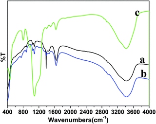 | ||
| Fig. 3 FTIR spectra of the as-prepared (a) core, (b) core/shell and (c) core/shell/SiO2 nanoparticles. | ||
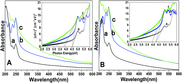
UV-Visible spectroscopy determines the colloidal stability and optical features of the prepared core, core/shell and core/shell/SiO2 NPs over the range from 200–600 nm in the UV-Visible region (Fig. 4). The absorption spectra consist of a strong peak at 248 nm and another peak at 205 nm with a shoulder (232 nm), which correspond to the transitions from the ground state 2F5/2 of Ce3+ to different components of the excited Ce3+ 5d states split by the crystal field.24,33 Furthermore, Ce3+ and Tb3+ are co-doped in the LaF3 matrix, in which Ce3+ absorbs light and transfers energy to Tb3+, and Tb3+ emits green light. Due to the strong absorption in the wavelength range between 200 and 300 nm resulting from the 4f–5d transition of Ce3+, the LaF3 doped with Ce3+ and Tb3+ emitted bright green fluorescence upon irradiation.24 These observed bands are consistent with the literature reported data for f–d electron transitions in LaF3:Ce/Tb and indicate that useful optical properties were retained in the as-prepared nanostructured materials. As shown in Fig. 4, a great enhancement in the absorption spectrum is observed, and it indicates the surface modification of the prepared NPs. Due to the coating of the amorphous silica surface around the core/shell NPs, they have a hydrophilic nature in aqueous solvents. These hydrophobic surface functional groups are responsible for enhancing the solubility character of the nanomaterials because they easily form hydrogen bonds within the aqueous solvents. We observed a similar trend in the absorption spectra measured in ethanol. Tauc and Menth's method was applied for the determination of the optical properties and their correlation between the band gap energies and the grain sizes of the as-prepared core, core/shell, core/shell/SiO2 NPs.34 As illustrated in Fig. 4, the experimentally calculated band gap energies decreased upon increasing the surface coating around the core-NPs. It is observed that crystallinity decreases upon increasing the surface coating and this trend is followed in the band gap energies after surface coating, which could be due to the size effect.
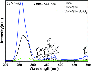
The comparative photoluminescence spectra and lifetime measurements were obtained at room temperature for the core, core/shell and core/shell/SiO2 NPs to investigate the impact of shell formation on the optical features of the nanoproducts. Fig. 5 displays the excitation spectra of the core, core/shell and core/shell/SiO2 NPs monitored at an emission wavelength of 541 nm. The excitation spectra consist of a broad and strong band with some weak intensity peaks monitored at 317(7F6 → 5D0), 326(7F6 → 5D1), 340(7F6 → 5L8), 351(7F6 → 5D10), 359(7F6 → 5G5), 370(7F6 → 5G6), and 379(7F6 → 5D3) nm originating from the intra-configurational parity forbidden 4f–4f excitation electronic transitions from the 7F6 ground state to the labeled excited states of the Tb3+ ions along with the strong band located at 275 nm corresponding to the 4f–5d transition of the Ce3+ ion.13,35,36 The excitation spectra show a similar trend in all samples and all excitation transitions are identical to the excitation of the Tb3+ ion in the powder samples.13,35,36 It indicates that efficient energy transfer from Ce to Tb occurs in the core, core/shell and their core/shell/SiO2 NCs. These observed excitation transitions of Tb3+ ions agree well with the published literature reports.13,35,36 As seen in Fig. 5, the peak intensities of the 4f–4f transitions of the Tb3+ ions increased in the core/shell NPs, which may be related to the surface growth of the inert LaF3 layer surrounding the core-NPs. Whereas, the relative peak intensity decreases after porous silica surface modification, due to the influence of amorphous silica.
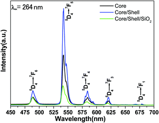
Fig. 6 illustrates the comparative emission spectra of core, core/shell and core/shell/SiO2 NPs excited from 264 nm under similar experimental conditions within the spectral range from 400–700 nm. The emission spectra of all three samples are composed of six strong emission transitions in the visible region assigned to 488 nm (5D4 → 7F6), 542 nm (5D4 → 7F5), 584 nm (5D4 → 7F4), 620 nm (5D4 → 7F3) and 677 nm (5D4 → 7F1) derived again from the intra-configurational parity forbidden 4f–4f excitation electronic transitions originating from the 5D4 ground state to the labeled excited states of the Tb(III) ions.12,13,32 Among the emission transitions the most prominent intensive broad emission band observed at 543 nm is due to the (5D4 → 7F5) transition and exhibits the strongest green emission, which is known as the hypersensitive one. This hypersensitive emission transition is the genuine fingerprint of the characteristic emission line corresponding to the 4f–4f transition of the Tb3+ ion, which is induced by the change in the chemical environment of the Tb3+ ion during the formation of a new chemical bond between the surface coated LaF3 shell and the Tb3+ metal ions. As seen in Fig. 6 the emission intensity of this transition is stronger than those of other transitions, indicating that the spectrum is dominated by the hypersensitive transition from 5D4 to the 7F5 manifold, whereas the other emission peaks are comparatively weak.12,23,29,32 It is noticeable that magnetically dipole allowed transitions are observed at the same peak position with a high emission intensity because of the similar crystal structure. The comparative emission spectra suggest that the peak positions of the Tb3+ ions are not affected and that the structure and luminescence properties of LaF3:Ce/Tb3+phosphor are not destroyed after covering the inert LaF3 and amorphous SiO2 layers surrounding the LaF3:Ce/Tb NPs, which could be due to the fact that there is no alteration in the symmetry of the core lattice. Notably, the relative peak intensity is albeit a little stronger in the core/shell NPs compared to the core-NPs. The increased intensity could have resulted from the increase in the crystalline size of the core-NPs after surface growth of a similar inert crystal structure LaF3 shell. Moreover, the growth of the inert LaF3 shell around the core-NPs protects the doped luminescent lanthanide ions from non-radiative transitions, which originate from high vibration energies or other quenching sites located at the surface of the NPs. Therefore, we expected that after surface coating with the insulating layer of a similar crystal structure a physical barrier is observed between the optically active core and the surrounding surface medium, reducing the non-radiative pathways. It is known that the emission intensity of luminescent lanthanides ions will be quenched to some extent in an environment that has a high phonon frequency, such as –OH groups, which have a high vibrational frequency near 3450 cm−1, which has also been confirmed by FTIR results.12 As a result, epitaxial growth of an undoped LaF3 layer effectively reduces non-radiative quenching of the luminescent core through surface defects and surrounding surface adsorbed organic moieties. Furthermore, considerable enhancement in luminescence efficiency is attributed to the fact that the LaF3 layer has been grafted successfully, which protects the core-NPs from Ce3+ oxidation. Although after epitaxial growth of an inert shell surrounding the luminescent core NPs, their solubility in aqueous solvent is reduced. The solubility and emission intensity of the as-prepared nanomaterials are important factors; however the toxicity for cells could be 10 times more critical for bioimaging applications and therefore, it should be taken as a priority in the design of nanolabels. In order to improve the colloidal solubility in aqueous solvents, subsequently, we grafted an amorphous silica layer around the core/shell NPs through the hydrolysis and condensation of silanol groups.27,28 However, after coating, a silica layer luminescence intensity is suppressed to some extent because of the light scattering effect on both emission and incident light by the porous silica layer. This phenomenon can be attributed to the involvement of large vibrational modes, such as Si–OH on the surface of the NPs, which may cause a considerable non-radiative transition and reduce the luminescence intensity of the luminescent lanthanide ions. A lot of papers have also reported that non-radiative centers such as –OH groups exist on the surface.12,13,28 And they have proven that the silica surface modified NPs could suppress the luminescence intensities because the silica shell network amplifies the surface defects. On the other hand, these luminescence quenching silanol molecules greatly enhanced the solubility, colloidal stability, biocompatibility and nontoxic nature of the as-prepared NPs. The amorphous silica coating was used in our work for further biological applications and to maintain luminescence efficiency.
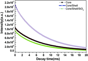
The energy transfer efficiency from a donor (Ce3+) to an acceptor (Tb3+) can be calculated according to the formula ηET = 1 − Id/Id0, where Id and Id0 are the corresponding luminescence donor intensities in the presence and the absence of the acceptor for the same donor concentration, respectively. The energy transfer efficiencies are 45%, 79% and 25% for core, core/shell and core/shell/SiO2 NPs, respectively. It is observed from the emission spectral results that the energy transfer efficiency increased after inert shell coating, whereas after silica surface modification it greatly decreased. Photoluminescence decay curves of the 5D4 level (542 nm) of the Tb3+ ion for the core, core/shell, and core/shell/SiO2 NPs, under 264 nm excitation, are shown in Fig. 7. All the luminescence decay data were collected at room temperature. The decay curve for the 7F5 → 5D4 transition (542 nm) of Tb3+ ions can be well fit in the single exponential function as I = I0![[thin space (1/6-em)]](https://www.rsc.org/images/entities/char_2009.gif) exp(−t/τ1) (Fig. 7), where I0 and I are the intensities at t = 0 and t ms and τ is the lifetime (1/e lifetime of the Ce/Tb emission center).36 As seen in Fig. 7, the decay time for the core/shell (4.42 ms) sample is higher compared to those for the core (3.21 ms) and core/shell/SiO2 NPs (2.82 ms), and it indicates that the quenching centers have been removed after inert shell formation. However, the measured luminescence decays indicate that the quenching centres have been formed after amorphous silica surface encapsulation surrounding the core/shell NPs. The FT-IR spectra suggest the presence of water molecules and, what seems even more possible, –OH groups in the SiO2 shell which quenched the exicited states of Tb3+ and additionally lowered the luminescence intensity of the core/shell/SiO2 NPs. This luminescent quencher scattered the emission light and enhanced the non-radiative transition resulting in the reduced luminescence intensity, these observations are consistent with FTIR and UV/Vis results. Whereas, amorphous silica surface modified NCs possess hydrophilic silanol groups, which are highly dispersible in aqueous solvent through electrostatic stabilization forces. Our observed results are strongly supported by previously published literature reports.6,25
exp(−t/τ1) (Fig. 7), where I0 and I are the intensities at t = 0 and t ms and τ is the lifetime (1/e lifetime of the Ce/Tb emission center).36 As seen in Fig. 7, the decay time for the core/shell (4.42 ms) sample is higher compared to those for the core (3.21 ms) and core/shell/SiO2 NPs (2.82 ms), and it indicates that the quenching centers have been removed after inert shell formation. However, the measured luminescence decays indicate that the quenching centres have been formed after amorphous silica surface encapsulation surrounding the core/shell NPs. The FT-IR spectra suggest the presence of water molecules and, what seems even more possible, –OH groups in the SiO2 shell which quenched the exicited states of Tb3+ and additionally lowered the luminescence intensity of the core/shell/SiO2 NPs. This luminescent quencher scattered the emission light and enhanced the non-radiative transition resulting in the reduced luminescence intensity, these observations are consistent with FTIR and UV/Vis results. Whereas, amorphous silica surface modified NCs possess hydrophilic silanol groups, which are highly dispersible in aqueous solvent through electrostatic stabilization forces. Our observed results are strongly supported by previously published literature reports.6,25
4. Conclusions
In summary, a well crystallized luminescent LaF3:Ce/Tb core from inert LaF3 and amorphous silica shell surface modified NPs was prepared using the polyol process. Our observed results suggest that the crystal structure, optical, photoluminescence and lifetime properties were greatly affected after shell formation. FE-TEM micrographs clearly exhibit the successful amorphous silica surface modification surrounding the core/shell NPs. These luminescent core, core/shell and core/shell/SiO2 NPs ranging from 10–20 nm, which are of irregular hexagonal shape, can be well dispersed in aqueous and non-aqueous solvents. The gradual decrease in the calculated band gap energy after shell formation predicts that the growth of the layer increases the particle size of the nanoproducts. The enhanced luminescence intensity and the decay time of the core/shell NPs may be due to the decreased non-radiative process on the surface of luminescent core-NPs. Our findings suggest that surface functionalization of core NPs plays a most important role in the modification of the observed optical and photoluminescence properties of core/shell and core/shell/SiO2 NPs. We believe that these core/shell/SiO2 NPs can be potentially used for luminescence bio-labeling in biomedical sciences.Acknowledgements
This work was supported through the project funded by the National Plan for Science, Technology and Innovation, (MAARIFAH) King Abdulaziz City for Science and Technology, Kingdom of Saudi Arabia, award Number (13-Bio1246-02).References
- Z. Chen, W. Zheng, P. Huang, D. Tu, S. Zhou, M. Huang and X. Chen, Nanoscale, 2015, 7, 4274 RSC.
- P. Huhtinen, M. Kivela, O. Kuronen, V. Hagren, H. Takalo, H. Tenhu, T. Lovgren and H. Harma, Anal. Chem., 2005, 77, 2643 CrossRef CAS PubMed.
- G. Chen, C. Yang and P. N. Prasad, Acc. Chem. Res., 2013, 4, 61474 Search PubMed.
- C. Liu, Y. Hou and M. Gao, Adv. Mater., 2014, 26, 6922 CrossRef CAS PubMed.
- G. Chen, H. Ågren, T. Y. Ohulchanskyya and P. N. Prasad, Chem. Soc. Rev., 2015, 44, 1680 RSC.
- W. Zheng, S. Zhou, Z. Chen, P. Hu, Y. Liu, D. Tu, H. Zhu, R. Li, M. Huang and X. Chen, Angew. Chem., Int. Ed., 2013, 52, 6671 CrossRef CAS PubMed.
- S. V. Eliseeva and J. C. G. Buenzli, Chem. Soc. Rev., 2010, 39, 189 RSC.
- A. D. Ostrowski, E. M. Chan, D. J. Gargas, E. M. Katz, G. Han, P. J. Schuck, D. J. Milliron and B. E. Cohen, ACS Nano, 2012, 6, 2686 CrossRef CAS PubMed.
- X. D. Wang, J. A. Stolwijk, T. Lang, M. Sperber, R. J. Meier, J. Wegener and O. S. Wolfbeis, J. Am. Chem. Soc., 2012, 134, 17011 CrossRef CAS PubMed.
- E. Downing, L. Hesselink, J. Ralston and R. Macfarlane, Science, 1996, 273(5279), 1185 CAS.
- A. A. Ansari, R. Yadav and S. B. Rai, RSC Adv., 2016, 6, 22074 RSC.
- A. A. Ansari, A. K. Parchur, M. Alam and A. Azzeer, Mater. Chem. Phys., 2014, 147, 715 CrossRef CAS.
- A. K. Parchur, A. I. Prasad, A. A. Ansari, S. B. Rai and R. S. Ningthoujam, Dalton Trans., 2012, 11032 RSC.
- P. Reiss, M. Protiere and L. Li, Small, 2009, 5, 154 CrossRef CAS PubMed.
- F. Vetrone, R. Naccache, V. Mahalingam, C. G. Morgan and J. A. Capobianco, Adv. Funct. Mater., 2009, 19, 2924 CrossRef CAS.
- A. Kar, S. Kundu and A. Patra, ChemPhysChem, 2015, 16, 505 CrossRef CAS PubMed; A. Kar and A. Patra, Nanoscale, 2012, 4, 3608 RSC; P. Ghosh, E. de la Rosa, J. Oliva, D. Solis, A. Kar and A. Patra, J. Appl. Phys., 2009, 105, 113532 CrossRef.
- J. C. Boyer, J. Gagnon, L. A. Cuccia and J. A. Capobianco, Chem. Mater., 2007, 19, 3358 CrossRef CAS.
- J. W. Stouwdam and F. C. J. M. van Veggel, Langmuir, 2004, 20, 11763 CrossRef CAS PubMed.
- J. Wang, S. Bo, L. Song, J. Hu, X. Liu and Z. Zhen, Nanotechnology, 2007, 18, 465606 CrossRef PubMed.
- Y. Zhang and M. Lu, Nanotechnology, 2007, 18, 275603 CrossRef.
- T. Samanta, S. Sarkar, V. N. Adusumalli, A. E. Praveen and V. Mahalingam, Dalton Trans., 2016, 78 RSC.
- P. Ghosh, A. Kar and A. Patra, Nanoscale, 2010, 2, 1196 RSC; P. Ghosh, A. Kar and A. Patra, J. Appl. Phys., 2010, 108, 113506 CrossRef CAS; P. Ghosh and A. Patra, J. Phys. Chem. C, 2008, 112, 19283 Search PubMed; P. Ghosh and A. Patra, J. Phys. Chem. C, 2008, 112, 3223 Search PubMed.
- Y. Liu, W. Chen, S. Wang, A. G. Joly, S. Westcott and B. K. Woo, J. Appl. Phys., 2008, 103, 063105 CrossRef.
- M. Y. Xie, L. Yu, H. He and X. F. Yu, J. Solid State Chem., 2009, 182, 597 CrossRef CAS.
- L. Zhu, J. Meng and X. Cao, J. Nanopart. Res., 2008, 10, 383 CrossRef CAS.
- C. Mi, T. Wang, P. Zeng, S. Zhao, N. Wang and S. Xu, Anal. Methods, 2013, 5, 1463 RSC.
- A. A. Ansari, S. P. Singh, N. Singh and B. D. Malhotra, Spectrochim. Acta, Part A, 2012, 86, 432 CrossRef CAS PubMed.
- A. A. Ansari, M. Alam, J. P. Labis, S. A. Alrokayan, G. Shafi, T. N. Hasan, N. A. Syed and A. A. Alshatwi, J. Mater. Chem., 2011, 21, 19310 RSC.
- R. Mangaiyarkarasi, S. Chinnathambi, P. Aruna and S. Ganesan, J. Nanopart. Res., 2015, 17, 136 CrossRef.
- V. S. Marques, L. S. Cavalcante, J. C. Sczancoski, A. F. P. Alcantara, M. O. Orlandi, E. Moraes, E. Longo, J. A. Varela, M. S. Li and M. R. M. C. Santos, Cryst. Growth Des., 2010, 10, 4752 CAS.
- A. A. Ansari, T. N. Hasan, N. A. Syed, J. P. Labis, A. K. Parchur, G. Shafi and A. A. Alshatwi, Nanotechnol. Biol. Med., 2013, 9, 1328 CrossRef CAS PubMed.
- A. A. Ansari and J. P. Labis, J. Mater. Chem., 2012, 22, 16649 RSC.
- Z. Tian, G. Hai and Q. Yanmin, J. Lumin., 2009, 129, 861 CrossRef.
- J. Tauc and A. Menth, J. Non-Cryst. Solids, 1972, 8/9, 569 CrossRef.
- N. Yaiphaba, R. S. Ningthoujam, N. R. Singh and R. K. Vatsa, Eur. J. Inorg. Chem., 2010, 2682 CrossRef CAS.
- G. Gao, A. W. Beckmann, O. Surzhenko, C. Dubs, J. Dellith, M. A. Schmidt and L. Wondraczek, Sci. Rep., 2015, 5, 8942–8946 CrossRef PubMed.
| This journal is © the Partner Organisations 2017 |

