High performance dye anchored counter electrodes with a SPSQ2 sensitizer for dye sensitized solar cell applications†
K.
Susmitha
a,
M.
Gurulakshmi
a,
M.
Naresh Kumar
b,
L.
Giribabu‡
cd,
G.
Hanumantha Rao
cd,
Surya Prakash
Singh‡
cd,
S.
Narendra Babu
b,
M.
Srinivas
e and
M.
Raghavender‡
*a
aDepartment of Physics, Yogi Vemana University, Kadapa 516003, India. E-mail: toraghavender@rediffmail.com
bOsmania University College for Women, Department of Physics and Electronics, Koti, Hyderabad 500095, India
cInorganic and Physical Chemistry Division, CSIR-Indian Institute of Chemical Technology (IICT), Hyderabad 500007, India
dAcademy of Scientific and Innovative Research, CSIR-IICT, Hyderabad 500007, India
eDepartment of Physics, Osmania University, Hyderabad 500 007, India
First published on 27th October 2016
Abstract
High performance counter electrodes (CEs) based on dye anchoring have been developed via a low cost spray gun. Their performance was further optimized using PEDOT:PSS over the dye anchored counter electrode (DACE). Here we demonstrate DACE based devices using a near-infrared unsymmetrical squaraine sensitizer (SPSQ2) and commercially available N719 dye. The electrochemical impedance spectroscopy (EIS) results reveal that the charge transfer activity of the DACE devices shows a more optimal performance than those without DACEs. A significant increase in photoconversion efficiency was observed for the PEDOT:PSS sprayed DACE (5.75%) as the counter electrodes associated with low series resistance, low electrolyte diffusion impedance, high open circuit voltage and fill factor when compared to the simple DACE and normal counter electrode DSSCs. The enhanced efficiency could be due to the charge carriers generated in the test cells associated with SPSQ2 dye on the counter electrode and an additional PEDOT:PSS layer on the DACE.
Introduction
Photovoltaic (PV) solar cells are well-designed and attractive devices for energy production. New concepts, such as dye sensitized solar cells (DSSCs), have progressed to a stage very close to possible commercialization. DSSCs were first invented by Grätzel and co-workers,1 and received much attention as a promising alternative to conventional solar energy conversion devices because of their low cost production, environmentally friendly components, better performance in diffuse light, less dependence of the performance on the angle of light incidence, transparency, color, lower energy consumption during manufacture and relatively high energy conversion efficiency. A power conversion efficiency of 13%2 has been achieved for DSSC devices. The major components of the photo-related portion of the DSSCs are dye, redox shuttle, a photo electrode and a counter electrode, which have been investigated independently over the past 15 years, and the most efficient device architecture remains essentially unchanged from its conception.The counter electrode is one of the major essential components of DSSCs. The CEs reduce the redox species, which are used as mediators in the regeneration of the sensitizer after electron injection. The reactions at the CE are dependent on the type of redox mediator used to transfer charge among the photo electrode and the counter electrode. In most of the DSSCs, the iodide tri-iodide couple has been employed as the redox mediator and the overall redox reaction in the DSSCs can be described as: I3− + 2e− ↔ 3I−. The tri-iodides are generated near the dye sensitized TiO2 electrode and reduced at the counter electrode. Platinum loaded conducting glass has been widely employed as the standard CE for DSSCs due to its high catalytic activity and excellent conductivity as well as its high corrosion stability against iodine in the electrolyte.3–5
The architecture of the DACE or counter electrode was modified6 by Nam-Gyu Park, with a structure containing two different dyes in the solar cell at the photo and counter electrodes. This method allows the TiO2 layers on the photo and counter electrodes to experience high temperature annealing without damaging the dye molecules. The results of photocurrent transient measurements revealed that photoexcited electrons at the TiO2 layer on the Pt CE progressed initially in the opposite direction at the beginning stage of light illumination, and immediately participated in the conversion process to enhance the performance.6 Scientists are making efforts to improve cell fabrication technology.
In this view, dye anchored counter electrode dye sensitized solar cells developed7 by our team using well studied N719 and PCH0018,9 dyes revealed a broad spectra of incident photon to current conversion efficiency (IPCE). Their performance was optimized with carbon nanohorns (CNHs), and an efficiency (η) of 7.14% was achieved.7 Recently, our group synthesized a near-infrared unsymmetrical squaraine sensitizer SPSQ210 for DSSC applications. The SPSQ2 revealed η = 3.08% in a volatile liquid electrolyte.10 A well studied N719 and near-infrared unsymmetrical squaraine SPSQ2 dye are used in the present study. Here, we optimized the DACE-DSSC performance with low cost PEDOT:PSS.
Experimental
Development of dye anchored mesoporous nanocrystalline TiO2 electrodes
F-Doped SnO2 (FTO) coated glass substrates (TCO22-7 Ω cm−1, Solaronix) were carefully cleaned using a mild detergent solution followed by deionized water, acetone and 2-proponol (Merck) in an ultrasonic bath to remove organics or any other contaminants, and dried under a N2 purge. A compact TiO2 blocking layer was deposited onto the surface of the above cleaned FTO by treating it with 40 mM TiCl4 solution at 70 °C for 30 min to achieve a good mechanical contact between the nanocrystalline TiO2 and the FTO glass substrate. The TiCl4 treated FTO glass plates were washed with deionized water and sintered at 500 °C for 30 min. The mesoporous TiO2 films (∼12 μm thickness) were developed using a screen printing method using 18NR-T (Dyesol) TiO2 paste and a 43T mesh screen, and sintered at 500 °C for 30 min. The above TiO2 coated substrates were again treated in 40 mM TiCl4 solution for 30 min at 70 °C. After cooling to 100 °C, the resultant substrates were immersed under dark conditions in two different dyes with variations in the dipping time. The details of the photo electrodes in SPSQ2, N719 dye and in a variation of dipping times are mentioned in Table 1. The dye used here, SPSQ2, was dissolved in chloroform, 3 × 10⁻⁴ M and N719 dye (Solaronix) in a mixture of tert-butanol/acetonitrile (1/1 v/v) with a concentration of 3 × 10⁻⁴ M. The photo electrode was removed from the solution, rinsed twice with the respective solvents to remove the unanchored dye molecules on the surface of the TiO2 film to ensure that the film was covered with a monolayer of dye molecules, followed by drying under a N2 purge; the dye anchored active electrode area was 0.36 cm2.| Test cell | Cell no. | Photo electrode | Counter electrode |
|---|---|---|---|
| SPSQ2 | 1 | FTO/TiO2/SPSQ2 (16 h) | FTO/Pt |
| N719/SPSQ2 | 2 | FTO/TiO2/N719 (2 h)/SPSQ2 (14 h) | FTO/Pt |
| DACE | 3 | FTO/TiO2/N719 (2 h)/SPSQ2 (14 h) | FTO/Pt/TiO2/SPSQ2 |
| PEDOT:PSS sprayed DACE | 4 | FTO/TiO2/N719 2(h)/SPSQ2 14(h) | FTO/Pt/TiO2/SPSQ2/PEDOT:PSS |
Development of counter electrodes (CEs)
Chloroplatinic acid hexahydrate (Sigma) was dissolved in 2-propanol, followed by ultrasonication for 50 min. To the resultant light yellow color solution, 10 mL of hydrochloric acid was added and it was ultrasonicated for 10 min. The resulting transparent platinum solution was used for the development of the counter electrodes. In detail, the FTO glass substrates were drilled using DREMEL 300 with a diamond tipped micro drill bit, and cleaned in 2-propanol, deionized water followed by absolute ethanol for 30 min. These substrates were placed over the hot plate (about 180 °C), which was adjusted during the spay, whereas the resultant platinum solution was loaded into a simple spray air brush which was connected to a N2 gas cylinder and the flow rate (1 mL min−1) was controlled through a 0.3 mm micro-tip needle and a gas regulator (Messar, Germany). These substrates were sintered at 500 °C for 10 min and used as counter electrodes.Development of dye anchored counter electrodes (DACEs)
The above prepared CEs were used to develop dye anchored counter electrodes. In detail, the 18NR-T titanium paste was coated over the counter electrodes in an area of 6 mm × 6 mm (0.36 cm2) using a screen printer and followed by sintering at 500 °C for 30 min. While cooling down to 100 °C, the substrates were immersed in SPSQ2 dye solution (in chloroform (3 × 10⁻⁴ M)) for 16 hours under dark conditions. These electrodes were denoted as DACEs. Furthermore, the filtered PEDOT:PSS solution was sprayed over the dye anchored area of the DACEs with an open mask of area 6 mm × 6 mm and its schematic representation is shown in Fig. 1. Its schematic set-up is shown in Fig. S1 (ESI†). The solution was slightly heated up to 120 °C for 5 min and the resulting electrodes were named as PEDOT:PSS sprayed DACEs. The photographs of the developed DACEs are shown in the inset of Fig. S1 (ESI†).Fabrication of dye sensitized solar cells with CEs and DACEs
The DSSC test cells were fabricated using similar methods as reported in our earlier studies.11 The photo electrodes were sandwiched with their respective counter electrodes and dye anchored counter electrodes using a thermal adhesive of 25 μm thick Surlyn film Meltonix 1170-25 (Solaronix) as a spacer. The assembly was then placed on a preheated hot plate (130 °C) and pressed gently to seal both the electrodes to produce sandwich-type cells labeled as DSSCs, DACE-DSSC and PEDOT:PSS sprayed DACE DSSC. The details of the test cells are given in Table 1, and the test cell architecture is shown in Fig. 2(a). The durable electrolyte Iodolyte Z-150 (Solaronix) was modified, injected through a pre drilled hole on the counter electrode side by using a back vacuum filling technique. The holes were sealed with Meltonix 1170-25 cover glass along with an adhesive film.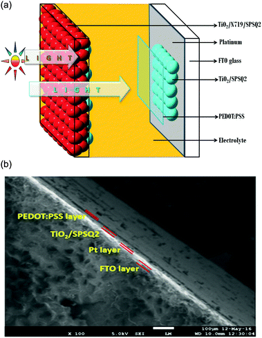 | ||
| Fig. 2 (a) DACE-DSSC architecture for optimum performance. (b) Cross sectional FE-SEM image of PEDOT:PSS sprayed dye anchored counter electrodes. | ||
Characterization and measurements
The absorption spectra of the photo electrodes were recorded using a UV-Vis-NIR Spectrophotometer (Agilent Technologies). Field Emission Scanning Electron Microscopy (FE-SEM) was done using an electron microscope (JEOL, model: 7610F, Oxford). The photocurrent density (J)–voltage (V) measurements of the test cells were conducted using a xenon arc solar simulator (PEC-L01, Peccell Inc., Japan) with an AM 1.5 spectral filter and a source meter (2401N Keithley Instruments Inc.), its light intensity was adjusted to 100 mW cm−2 AM 1.5 using a calibrated mono-Si solar cell. The electrochemical impedance spectroscopy (EIS) measurements were performed under 100 mW cm−2 using an IVIUMSTAT electrochemical workstation at an amplitude of 10 mV, and in a frequency range of 1 Hz to 1 MHz.Results and discussion
Fig. 2(b) represents the cross-sectional FE-SEM image of the developed PEDOT:PSS sprayed DACE. A thin PEDOT:PSS layer was deposited on the top of the SPSQ2 dye anchored counter electrodes and is clearly observed in Fig. 2(b). Filtered PEDOT:PSS solution was sprayed using a 0.3 mm micro-tip needle spray gun, and was controlled at a rate of 1 mL min−1 by using pure N2 gas.12 The total configuration of this dye anchored counter electrode was FTO/Pt/TiO2/SPSQ2/PEDOT:PSS. A very thin white colored film represents the platinum on the FTO glass substrate, over which TiO2 with a SPSQ2 film was clearly noticed.Fig. 3(a) shows the absorption spectra of the dye solutions and the dye anchored TiO2 films of N719, SPSQ2 and N719/SPSQ2. The absorption peaks of SPSQ2 at 690 nm and 640 nm correspond to the charge transfer and the peak at around 385 nm was assigned to the π–π* transition.10 The N719 dye anchored TiO2 film exhibits peaks at 410 nm and 545 nm, corresponding to the metal-to-ligand charge transfer. The N719/SPSQ2 sensitized TiO2 electrodes show higher absorbance maxima, however, in the near IR region a small absorption was observed.
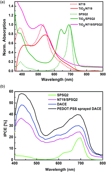 | ||
| Fig. 3 (a) Absorption spectra of the dye solutions and their sensitized TiO2 film. (b) Incident photon to current conversion efficiency spectra of the fabricated DSSCs. | ||
Fig. 3(b) represents the Incident Photon to Current Conversion Efficiency (IPCE) of the fabricated DSSCs. The higher IPCE of the DACE-DSSCs corresponds to the improved photocurrent generation. Broader IPCE spectra were observed for the DACE-DSSCs and this effect is reflected in the enhanced photovoltaic performance.
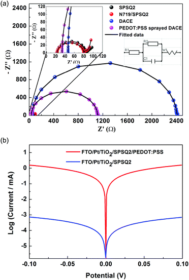
To investigate the electrochemical impedance characterization of the developed electrodes and the fabricated solar cells, we performed electrochemical impedance spectroscopy studies (EIS). An IVIUMSTAT electrochemical impedance analyzer was used and the Nyquist plots of the test cells are presented in Fig. 4(a) and Fig. S3 of the ESI.† All impedance parameters were extracted using a fitting equivalent circuit using IVIUMSOFT software and are summarized in Table 2. In typical EIS analysis, RS is the series resistance normally determined by monitoring the real axis intercept at the high frequency side and RCT and W are derived from semicircles in the high and low frequency regimes respectively. RCT represents the interfacial charge transfer resistances at the counter electrode/electrolyte interface for the I3−/I− redox reaction, and W provides the information on electrolyte diffusion impedance (Warburg impedance).
| SPSQ2 | N719/SPSQ2 | DACE | PEDOT:PSS sprayed DACE | |
|---|---|---|---|---|
| R1 (RS) (Ω) | 23.60 | 23.30 | 46.60 | 33.90 |
| R2 (RCT) (kΩ) | 0.085 | 0.081 | 2.35 | 1.08 |
| C1 (μF) | 1.62 | 1.52 | 2.48 | 2.20 |
| W (Ω) | 11.30 | 16.10 | 16.64 | 8.95 |
Semi-circles with higher RCT values were observed for the DACE and PEDOT:PSS sprayed DACE cells, however, a lower RCT value with a small tail peak was present in the lower frequency regime for devices without DACE cells. TiO2 with dye loading on the counter electrode resultant DACE based DSSCs exhibits higher charge transfer resistances that contribute to the electron transfer kinetics at the electrolyte/electrode interface, which associates with its inferior electron transfer. The PEDOT:PSS sprayed DACE showed the smallest electrolyte diffusion impedance W (8.95 Ω) value among the four counter electrodes, which may favourably influence the solar cell performance. The diffusion impedance in these counter electrodes was attributed to their compact surface morphologies, which significantly hampers the diffusion behaviour of the electrolyte throughout the CEs. In addition, the higher impedance values of the counter electrodes will affect the cell performance in the succeeding facets, the electrical performance or sheet resistance and electrochemical nature or catalysis effectiveness, which was typically determined by the inverse of charge transfer resistance and optical properties or reflection of light.13–15 The inverse of charge transfer resistance value for the PEDOT:PSS sprayed DACEs was higher (0.92 × 10⁻³) compared to the DACEs (0.42 × 10⁻³), which gave a higher rate of catalysis redox reduction at the counter electrode side indicating that a greater number of negatively charged ions were accumulated, and is also reflected in the higher Voc values. The area of the PEDOT:PSS sprayed DACEs was higher compared to the bare DACEs (Fig. 1).
Tafel polarization measurements were performed using symmetrical dummy cells16 (two similar counter electrodes are sandwiched followed by filling the same electrolyte into the cell to get the symmetrical dummy cells) to confirm the interfacial charge-transfer properties of the redox couple on the DACE surface. The corresponding Tafel polarization plots are shown in Fig. 4(b). The anodic and cathodic branches of the Tafel curve for the PEDOT:PSS sprayed DACEs showed a larger slope indicating the higher exchange current density. Thus the Tafel polarization results suggest the superior electrocatalytic activity of the PEDOT:PSS sprayed DACEs. From these electrochemical studies, the PEDOT:PSS sprayed DACEs are expected to show a reasonably higher power conversion efficiency.
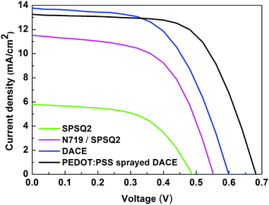
The EIS and Tafel results indicate that the DACE and PEDOT:PSS sprayed DACE electrodes developed through a spray coat approach can be potential counter electrodes for high performance DSSCs. Subsequently, the developed DACEs were sandwiched with N719 sensitized TiO2 electrodes to fabricate DSSC devices. For comparison, the platinum and TiO2/SPSQ2 dye loaded counter electrodes were also exploited as CEs. The photocurrent density (JSC)–voltage (V) characteristic curves of DSSCs fabricated with various CEs measured under illumination of 100 mW cm−2 AM 1.5 are shown in Fig. 5 and the corresponding photovoltaic parameters include open circuit voltage (Voc), short circuit current density (JSC), fill factor (FF) and power conversion efficiency (η) that are summarized in Table 3 (09 cells fabricated for each type, reported high performance test cell values). These are represented by equations FF = (Pmax)/(JSCVoc) and η = (Pmax × 100)/(Pin), where Pin is the input illumination light power and Pmax is the maximum power output from the cells. As expected, the devices without DACE cells showed a low power conversion efficiency of 1.60 and 3.60%.
| DSSCs | SPSQ2 | Published worka![[thin space (1/6-em)]](https://www.rsc.org/images/entities/char_2009.gif) 10 10 |
N719/SPSQ2 | DACE | PEDOT:PSS sprayed DACE |
|---|---|---|---|---|---|
| a Volatile acetonitrile based electrolyte. b J SC = ±0.20 mA cm−2, VOC = ±30 mV, FF = ±0.03, η = ±0.10. | |||||
| V oc (V) | 0.49 | 0.67 | 0.55 | 0.59 | 0.65 |
| J SC (mA cm−2) | 5.81 | 6.24 | 11.51 | 13.76 | 13.25 |
| Fill factorb (FF) | 0.56 | 0.72 | 0.58 | 0.57 | 0.63 |
| Efficiency (η)b (%) | 1.60 | 3.08 | 3.60 | 4.74 | 5.75 |
As a result of dye anchoring over the CEs, the conversion efficiency of the cells based on DACEs increased to 4.74%. The corresponding open circuit voltage (Voc), short circuit photocurrent density (JSC), and fill factor (FF) in the solar cells is 0.59 V, 13.76 mA cm−2 and 0.57 respectively. A further better power conversion efficiency was gained when the PEDOT:PSS solution was sprayed on the DACE based cells. The DSSCs based on the PEDOT:PSS sprayed DACE presented the highest conversion efficiency of 5.75%, with a Voc value of 0.65 V, a JSC value of 13.25 mA cm−2, and a FF value of 0.63. The photocurrent density (JSC) of the DACE cells was 13.76 mA cm−2, which is close to that of the PEDOT:PSS sprayed DACE cells, 13.25 mA cm−2, which is ascribed to their series resistance values. Compared with the TiO2/N719/SPSQ2 and DACE cells, the efficiency PEDOT:PSS sprayed DACE cells achieved an improvement of 59.7% and 21.3% respectively.
Among these devices, the device with a PEDOT:PSS sprayed DACE presented a high fill factor value (0.63), while the device with platinum associated with SPSQ2 showed the lowest fill factor value (0.56). Moreover, the open circuit voltage (Voc) and fill factor (FF) reflected the photovoltaic performance of the fabricated devices. For the PEDOT:PSS sprayed DACEs, the decrease of RS was beneficial to enhance the electron transportation ability and thereby to increase the fill factor of the DSSCs.17
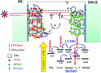
Fig. 6 depicts the energy level diagram of the DACE-DSSCs. After excitation of the dye (here SPSQ2) followed by release of electrons at the DACEs by light illumination, few electrons may transport to the photo electrode towards energy conversions, and few were moved to the electrolyte. Nevertheless, the exact working mechanism of the DACEs is not yet clear, which indicates that more work is to be done for this type of architecture device6 invented by Nam-Gyu Park.
Conclusions
In conclusion, dye anchored counter electrodes were developed using a low cost spray gun for dye sensitized solar cell applications. The optimal PEDOT:PSS sprayed DACE cell presents a power conversion efficiency of 5.75%, which is higher than the platinum based DSSCs in the present study. The superior performance, low series resistance, and higher open circuit voltage and fill factor were the major consensus of these electrodes. The enhanced efficiency could be due to the number of electrons generated in the test cell associated SPSQ2 dye on the counter electrode and the additional PEDOT:PSS layers on the DACEs. The DACE architect DSSCs could become potential devices with higher power conversion efficiencies.Acknowledgements
The author MR thanks DST-SERB (Department of Science and Technology-Science and Engineering Research Board), India, for financial support through the award of DST young scientist (SR/FTP/PS-111/2010). Authors thank Dr S. V. Manorama, IICT, Hyderabad, India, for FE-SEM characterization. MR thanks Dr K. Venkateswarlu, Dept. of Chemistry, YVU, for providing lab facilities. MR thank to DST-FIST [SR/FST/PSI-182/2012(C)].Notes and references
- B. O’Regan and M. Grätzel, Nature, 1991, 353, 737–740 CrossRef.
- S. Mathew, A. Yella, P. Gao, R. Humphry-Baker, B. F. E. Curchod, N. Ashari-Astani, I. Tavernelli, U. Rothlisberger, Md. K. Nazeerruddin and M. Grätzel, Nat. Chem., 2014, 6, 242–247 CrossRef CAS PubMed.
- X. Fang, T. Ma, G. Guan, M. Akiyama, T. Kida and E. Abe, J. Electroanal. Chem., 2004, 570, 257–263 CrossRef CAS.
- N. Papageorgiou, W. F. Maiera and M. Grätzel, J. Electrochem. Soc., 1997, 144, 876–884 CrossRef CAS.
- S. S. Kim, Y. C. Nah, Y. Y. Noh, J. Jo and D. Y. Kim, Electrochim. Acta, 2006, 51, 3814–3819 CrossRef CAS.
- H.-J. Koo, K. Kim, N.-G. Park, S. Hwang, C. Park and C. Kim, Appl. Phys. Lett., 2008, 92, 142103 CrossRef.
- K. Susmitha, M. Raghavender, M. Naresh Kumar and L. Giribabu, RSC Adv., 2016, 6, 22620 RSC.
- P. Y. Reddy, L. Giribabu, C. Lyness, H. J. Snaith, C. Vijaykumar, M. Chandrasekharam, M. Lakshmikanta, J. Hum, K. Kalyanasundaram, M. Grätzel and M. Nazeeruddin, Angew. Chem., Int. Ed., 2007, 46, 373 CrossRef CAS PubMed.
- L. Giribabu, C. Vijay Kumar, M. Raghavender, K. Somaiah, P. Yella Reddy and P. Venkateswara Rao, J. Nano Res., 2008, 2, 39 CrossRef CAS.
- G. Hanumantha Rao, A. Venkateswararao, L. Giribabu and S. Prakash Singh, Photochem. Photobiol. Sci., 2016, 15, 287–296 Search PubMed.
- K. Susmitha, M. Naresh Kumar, G. Rajkumar, L. Giribabu and M. Raghavender, Sol. Energy, 2015, 118, 126–133 CrossRef CAS.
- N. Charanadhar, K. Susmitha, M. Raghavender, L. Giribabu, K. Bhanu Sankara Rao, C. T. G. Smith, C. A. Mills, S. R. P. Silva and V. V. S. S. Srikanth, Sol. Energy, 2016, 137, 143–147 CrossRef.
- A. Hauch and A. Georg, Electrochim. Acta, 2001, 46(22), 3457–3466 CrossRef CAS.
- L. Han, N. Koide, Y. Chiba and T. Mitate, Appl. Phys. Lett., 2004, 84, 2433–2435 CrossRef CAS.
- N. Koide, A. Islam, Y. Chiba and L. Han, J. Photochem. Photobiol., A, 2006, 182, 296–305 CrossRef CAS.
- J. Theerthagiri, R. A. Senthil, M. H. Buraidah, M. Raghavender, J. Madhavan and A. K. Arof, J. Solid State Chem., 2016, 238, 113–120 CrossRef CAS.
- M. Ikegami, K. Miyoshi, T. Miyasaka, K. Teshima, T. C. Wei, C. C. Wan and Y. Y. Wang, Appl. Phys. Lett., 2007, 90(15), 153122 CrossRef.
Footnotes |
| † Electronic supplementary information (ESI) available. See DOI: 10.1039/c6qm00101g |
| ‡ These authors contributed equally to this work. |
| This journal is © the Partner Organisations 2017 |


