 Open Access Article
Creative Commons Attribution 3.0 Unported Licence
CdIn2S4/g-C3N4 heterojunction photocatalysts: enhanced photocatalytic performance and charge transfer mechanism
Di Lia,
Fenfen Shib,
Deli Jiangb,
Min Chenb and
Weidong Shi*b
aInstitute for Energy Research, Jiangsu University, Zhenjiang, Jiangsu, China 212013
bSchool of Chemistry and Chemical Engineering, Jiangsu University, Zhenjiang, Jiangsu, China 212013. E-mail: swd1978@ujs.edu.cn
First published on 22nd December 2016
Abstract
Heterojunction photocatalysts composed of CdIn2S4 (CIS) nanocrystals and graphitic carbon nitride (g-C3N4) nanosheets (CN) have been synthesized using a simple two-step wet chemistry method. In this system, CN nanosheets not only act as a substrate for the growth and uniform distribution of CIS nanocrystals but also play a key role in the photocatalytic degradation of organic pollutants with high efficiency. The CdIn2S4/g-C3N4 (CIS/CN) heterojunction photocatalysts exhibited better photocatalytic activity than that of pristine CIS and CN in photocatalytic degradation of both an organic dye (methyl orange) and an antibiotic (tetracycline hydrochloride). The enhanced photocatalytic performance might be ascribed to the formation of a heterojunction structure with strong interface interaction, which is beneficial to the photoinduced charge transfer between CIS and CN and efficient to accelerate the seperation of photogenerated electrons and holes. The as-synthesized heterojunction photocatalysts also showed good photocatalytic stability. After four cycles, the photocatalytic activity almost remains unchanged. The heterojunction photocatalysts with excellent photocatalytic performance and reusability may provide a new sight in the development of a photocatalyst with high efficiency for practical application of water purification.
Introduction
As the photocatalysis technology has attracted increasing attention in the field of energy, environment and materials in recent years, it is imperative to develop and prepare photocatalysts with excellent photocatalytic activity for practical applications.1–3 Graphitic carbon nitride (g-C3N4), due to it is a prototypical two-dimensional (2D) nanosheet photocatalyst with suitable band gap (∼2.7 eV), large specific surface area and good chemical stability, has been considered as a promising photocatalytic material.4–7 Though many works already have been focused on developing high performance g-C3N4 photocatalysts, due to its low light-harvesting ability, high inclination for recombination and slow interfacial kinetics for photocatalytic reaction, the solar-to-energy conversion efficiency of g-C3N4 photocatalyst is still far away from practical applications.8–10To suppress the charge recombination and enhance the performance of g-C3N4, several ways can be attempted including variation of morphology, doping and constructing heterojunctions.11–15 To date, the charge separation method that is widely used and focuses on the creation of a heterojunction structure by combining g-C3N4 with other semiconductors has attracted considerable attention because of its effectiveness in photoinduced charge separation.16–19 For example, Zhang et al. successfully constructed SnNb2O6 nanosheet/g-C3N4 nanosheet two-dimensional heterostructures. The optimum photocatalytic activity of SnNb2O6/g-C3N4 heterostructure is 30% for the degradation of organic pollution, which is about 3.9 times higher than that of pristine g-C3N4.20 Shi et al. coupled NaNbO3 nanowires with g-C3N4 to fabricate g-C3N4/NaNbO3 nanowire heterojunction photocatalysts and due to the strong interface interaction between g-C3N4 and NaNbO3, the as-synthesized photocatalyst improved over 8-fold higher activity than that of the pristine g-C3N4 for CH4 production in visible-light-driven CO2 reduction.21 The strategies of this method are the transfer of electrons from the conduction band (CB) of semiconductor I with more negative position to the CB of the semiconductor II with less negative position and the migration of holes from the valence band (VB) of semiconductors II with more positive position to the VB of the semiconductors I with less positive position, which are resulted by the space-charge region at the interface and the induced electric field. This will endow the photocatalysts with better carrier separation efficiency, longer carrier lifetimes and enhanced photocatalytic reaction rates.
In this study, CdIn2S4/g-C3N4 heterojunction photocatalysts have been synthesized by a two-step wet chemistry method. The CdIn2S4 exhibited nanocrystal structure with a size less than 100 nm, the g-C3N4 showed a typical two-dimensional nanosheet shape, and the heterojunction photocatalysts have a close contact interface, which is beneficial to the charge transfer. A series of characterizations such as XPS spectra demonstrated the formation of heterojunction and the strong interface interaction between CdIn2S4 and g-C3N4. The as-prepared CdIn2S4/g-C3N4 heterojunction photocatalysts exhibited enhanced photocatalytic performance in the degradation of organic dye (MO) and antibiotic (TC). In addition, on the basis of the photocatalytic activity of photocatalysts, trapping experiment, and ESR spectra, the possible photocatalytic mechanism for the enhanced photocatalytic activity of the CdIn2S4/g-C3N4 was discussed in detail.
Experimental section
Synthesis of CdIn2S4/g-C3N4 heterojunction photocatalysts
g-C3N4 nanosheets were prepared according to the previously reported method.22 The CdIn2S4/g-C3N4 heterojunction photocatalysts were synthesized by a hydrothermal method. In a typical experiment, 0.0277 g of Cd(NO3)2·4H2O and 0.0878 g of In(NO3)3·4.5H2O were added into 15 mL of distilled water, which contains 0.14 g of g-C3N4. Then, 16.3 mL of mercaptoacetic acid aqueous solution (0.2 mol L−1) and 3.25 mL of aqueous solution of sodium sulfide (0.2 mol L−1) were added into the abovementioned mixture. After stirring for another 1 h, the mixture was transferred into a Teflon-lined stainless steel autoclave (50 mL) and heated at 180 °C for 12 h, and then naturally cooled to room temperature. After washing several times with distilled water and ethanol, the as-obtained samples were dried in vacuum at 60 °C. The bare CdIn2S4 was synthesized by the same method without the addition of g-C3N4. The g-C3N4 sample is denoted as CN, CdIn2S4 is denoted as CIS, and CdIn2S4/g-C3N4 is denoted as CIS/CN.Characterization
Transmission electron microscopy and high resolution transmission electron microscopy (TEM and HRTEM) images were taken on a Tecnai G2 F30 S-TWIN TEM instrument (FEI, America) with an accelerating voltage of 300 kV. Purity and crystallization of the products were characterized by powder X-ray diffraction on a D8 advance X-ray spectrometer (Bruker, Germany) with Cu-Kα radiation (λ = 1.5406 Å). X-ray photoelectron spectroscopy (XPS) was performed on an ADES 400 (VG, England) instrument with Mg K-ADES source. UV-vis diffuse reflectance spectra (DRS) were obtained on a Shimadzu UV-2401 spectrophotometer equipped with a spherical diffuse reflectance accessory. The electron spin resonance (ESR) signals of spin-trapped radicals were measured on a Bruker model ESR JES-FA200 spectrometer using spin-trap reagent DMPO in water and methanol. The photocurrent and electrochemical impedance spectroscopy (EIS) measurements were carried out in a conventional three-electrode, single-compartment quartz cell on an electrochemical station (CHI 660D).Photocatalytic experiments
The photocatalytic activities of the CIS/CN were tested in the degradation reaction of methyl orange (MO, 10 mg L−1) and tetracycline hydrochloride (TC, 10 mg L−1) under irradiation of a 500 W tungsten light lamp. For a typical photocatalytic experiment, 0.06 g of catalyst powder was added into 60 mL of the abovementioned MO solution in a quartz tube. Prior to the irradiation, the suspensions were magnetically stirred in the dark for 30 min to ensure the adsorption/desorption equilibrium. The abovementioned suspensions were kept under constant air-equilibrated conditions before and during the irradiation. At given time intervals (20 min or 30 min), about 4 mL of aliquots were sampled and centrifuged to remove the particles. The concentrations of MO and TC were monitored using a UV-vis spectrophotometer according to its absorbance at 464 nm and 356 nm, respectively.Results and discussion
The morphology and microstructure of the as-prepared photocatalysts were characterized by TEM images. As shown in Fig. 1a, the bare CIS exhibits quasi-octahedron nanostructure with a unit size less than 100 nm. The CN shows a typical two-dimensional nanosheet morphology with an ultra-thin thickness. When the heterojunction formed by CIS and CN, the CIS nanocrystals distribute on the surface of the CN nanosheets and show the close contact, which could be seen in Fig. 1c and d. The HAADF-STEM image (Fig. 1e) also further confirms the abovementioned results. The HRTEM image of CIS/CN shows that the lattice spacing is 0.325 nm, corresponding to (311) plane of cubic phase CIS. Due to the weak crystallinity, there is no apparent lattice spacing of CN shows in the HRTEM image.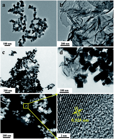 | ||
| Fig. 1 TEM images of pristine CIS (a), CN (b) and CIS/CN (c and d), HAADF-STEM image (e) and HRTEM image (f) of CIS/CN. | ||
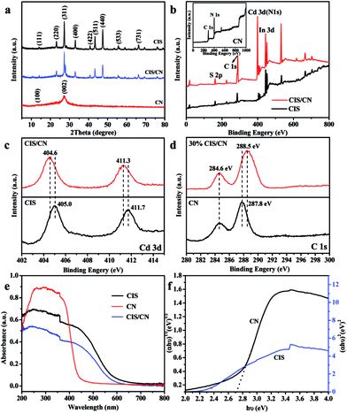
In the XRD pattern (Fig. 2a) of CIS/CN, all the diffraction peaks can be assigned to both CN and CIS, and there are no other peaks can be detected, which indicate that no impurity has been produced during the formation of the heterojunction. The (100) and (002) peaks at 13.2° and 27.1° are originated from graphitic carbon nitride. The diffraction peaks of as-prepared CIS can be assigned to cubic CdIn2S4 (JCPDS no. 27-0060) with lattice constants of a = 10.845 nm, and the 14.0°, 23.2°, 27.3°, 33.0°, 40.8°, 43.4°, 47.4°, 55.7°, and 66.2° can be indexed to the (111), (220), (311), (400), (422), (511), (440), (533) and (731) planes, respectively. In the CIS/CN, an obvious (002) diffraction peak of CN appeared along with the standard peaks of pristine CIS, demonstrating that the CIS/CN is a mixture of CIS and CN. No other diffraction peaks were detected, which indicates that no impurity phase has been generated during the hydrothermal process.
The surface chemical composition of CIS, CN and CIS/CN was investigated by XPS analysis. Fig. 2b shows the XPS survey spectra of CIS, CN and CIS/CN. C, N, Cd, In and S can be detected in the XPS survey spectrum of CIS/CN. No other signal can be detected in the XPS spectrum of CIS/CN, implying that no impurity has been generated during the composite process.
Fig. 2c exhibits the high-resolution XPS spectra of Cd 3d of CIS/CN and CIS. As exhibited in Fig. 2c, peaks at 404.6 and 411.3 eV of CIS/CN are attributed to Cd 3d5/2 and Cd 3d3/2,23 respectively, which shift slightly (∼0.4 eV) to the lower binding energy than the XPS peaks of CIS. Fig. 2d is the high-resolution XPS spectra of C 1s of CIS/CN and CN. The peaks at 284.6 eV of CIS/CN can be assigned to C–C graphite-like sp2 structure and 288.5 eV is attributed to N–sp3 C bond.24,25 Due to the strong electronic interaction between CIS and CN, the Cd 3d peaks of CIS/CN shift toward a lower binding energy region. Furthermore, the binding energy of N–sp3 C bond shifts about 0.3 eV to the higher binding energy than the XPS peaks of CN; however, the peak at 284.6 eV almost does not change, which indicates that the effect of CRef. 15: Please provide the last name for the 4th author.C bond on the interfacial interaction is less than the effect of C–N bond. These results imply that the CIS/CN is a heterojunction structure rather than a physical mixture of two pure phases of CIS and CN.26
As shown in the UV-vis spectra (Fig. 2e), the absorption band of CIS/CN is similar to the pure CIS, except that the absorption edge of CIS/CN shifts to the area of UV light, which might be caused by the addition of CN with poor visible light absorption ability. To investigate the band gap of CIS/CN, we calculated the band gap of CIS and CN using the Kubelka–Munk equation,27 and the plot of (αhν)x vs. hν (x = 1/2 or 2) for the band gap energy of CIS and CN is shown in Fig. 2f. Due to the direct gap nature of CIS and indirect gap nature of CN, the band gap of CIS and CN is approximately 2.3 eV and 2.7 eV, respectively. Both the band gap values of CIS and CN are close to previous literature reports.4,28
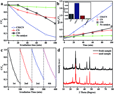
To investigate the photocatalytic activity of the as-prepared CIS/CN heterojunction photocatalyst, MO was used as a target organic pollutant, and photocatalytic degradation of MO under visible-light has been employed in this study. The MO exhibited very low degradation rate and reaction rate constant k under the visible-light irradiation in the absence of a photocatalyst in the photocatalytic system indicating the relative photostability of MO (Fig. 3a and b). As shown in Fig. 3a, after 100 min of photocatalytic reaction, the degradation rate of pure CIS and CN is 52% and 37%, respectively. However, the degradation rate of CIS/CN is much higher than both CIS and CN, and the value is 91%, which suggests that the CIS/CN exhibits better photocatalytic performance than CIS and CN. All of these data have excluded the effect of MO absorption on the surface of the photocatalysts. Fig. 3b shows the kinetic fit and degradation rate constant k for the degradation of MO with CIS, CN, CIS/CN and blank. All plots of ln(C0/C) against reaction time exhibit a linear relationship, indicating that the MO photocatalytic degradation was described well with the pseudo-first-order model.29 The reaction rate constant k of CIS, CN and CIS/CN is 0.00737, 0.00448 and 0.02349, and the k of CIS/CN is about 3.19 times and 5.24 times higher than pure CIS and CN, respectively.
We also studied the photocatalytic stability of CIS/CN in the degradation of MO, and the results are shown in Fig. 3c and d. As shown in Fig. 3c, after four recycles, the activity of photocatalytic degradation of MO remains relatively good, and only about 10% decline is observed than the first time. The XRD pattern of the used photocatalyst has almost no change, as shown in Fig. 3d. Both of these indicate that CIS/CN has superior stability during photocatalytic degradation of MO, and this is quite important in the practical application of a photocatalyst.
To further explore the photocatalytic performance of the as-prepared photocatalyst in degradation of other pollution, TC, as a typical antibiotic has been selected in our study. Fig. 4a shows the photocatalytic degradation curves. The CIS/CN shows the best photocatalytic activity in the entire photocatalysis process. When there is no photocatalyst in the photocatalysis reaction, a very low TC degradation was observed under visible-light irradiation, indicating that the TC is photochemically resistant. On adding the photocatalyst into the photocatalytic reaction, in the first 30 min, the degradation rate of CIS/CN reached 60%, whereas the degradation rates of CIS and CN are 30% and 20%, respectively. When the photocatalytic reaction time reaches 120 min, the degradation rate of CIS/CN is nearly 80% and the degradation rates of CIS and CN are about 60%. The better photocatalytic activity of CIS/CN might be due to the formation of heterojunction. The photocatalytic stability of CIS/CN in the degradation of TC also has been discussed in our study. As illustrated in the cycling runs curves (Fig. 4b), the CIS/CN heterojunction photocatalyst also exhibits excellent photocatalytic stability.
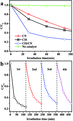 | ||
| Fig. 4 (a) Photocatalytic degradation of TC in the presence of CIS, CN, CIS/CN and in the absence of photocatalyst and (b) cycling runs for the photodegradation of TC with CIS/CN. | ||
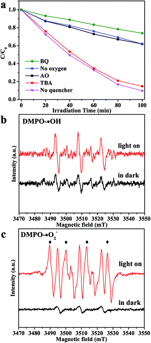
To deeply discuss the reaction mechanism, the main active species in the degradation process has been investigated by the trapping experiment, in which ammonium oxalate (AO) was used as the hole (h+) scavenger, 1,4-benzoquinone (BQ) was used as the ˙O2− scavenger, and tert-butanol (TBA) was used as the hydroxyl radical (˙OH) scavenger.30 As shown in Fig. 5a, when TBA was added in the reaction, the photocatalytic degradation rate shows very little decrease, which indicates that ˙OH plays a minor role in degradation of organic pollutants. In comparison, the photocatalytic activity of CIS/CN decreased apparently by the addition of AO and BQ, which suggests that h+ and ˙O2− act as main oxidative species in the process of photocatalytic degradation of organic pollution. Furthermore, when O2 is limited in the photocatalytic reaction, a great reduction of photocatalytic activity has been observed, which proves that O2 primarily acts as the efficient electron trap and results in the generation of ˙O2−.
For further confirmation of the abovementioned results, DMPO spin-trapping ESR technique has been adopted. As exhibited in Fig. 5b, the ESR signal intensities recorded with CIS/CN in an aqueous dispersion are almost the same as in the dark when the light is on, which suggests that there is little ˙OH generated in this system, and ˙OH is not the main reactive species. However, when the ESR signal intensities recorded with CIS/CN in methanol dispersion with the light on, the characteristic peaks of DMPO-˙O2− can be clearly detected and are quite sharper than in the dark condition. Thus, it is well recognized that ˙O2− can be generated in this system and played an important role in the photocatalytic degradation of organic pollutants, which are well consistent with the results of the trapping experiment.31
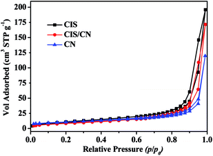
To understand the mechanism of photogenerated charge transfer in a CIS/CN heterojunction photocatalyst under visible-light irradiation, we first studied the specific surface area of CIS, CN and CIS/CN photocatalysts. Fig. 6 shows the adsorption–desorption isotherms from the adsorption branches. The N2 adsorption–desorption isotherm for all the photocatalyst samples is identified as a type IV isotherm with a H1 hysteresis loop according to Brunauer–Deming–Deming–Teller (BDDT) classification.32 The BET surface areas of CIS, CN and CIS/CN are 36.9 cm3 g−1, 36.6 cm3 g−1 and 30.5 cm3 g−1, respectively. The BET surface area of CIS/CN is smaller than both of CIS and CN, the reason might be that when the CIS and CN hybridize together, a part of the porous structure was blocked by the contact of CIS and CN. Thus, the effect of the specific surface area can be excluded for the enhanced photocatalytic activity of CIS/CN.
The band edge position of the photocatalyst valence band (EVB) and conduction band (ECB) is quite important in the discussion of a photogenerated charge transfer route. The EVB of the CIS can be calculated by the following equation:33
| ECB = χ − Ee − 0.5Eg |
| EVB = ECB − Eg |
On the basis of the abovementioned characterizations and results, a possible mechanism of charge transfer in CIS/CN is proposed. As shown in Fig. 7, because of the existence of an interface between CIS and CN, the electrons generated from CB of CN with more negative CB edge potential will transfer to the conduction band of CIS under the visible-light irradiation. Because the energies of CB edge of CIS is more negative than the standard redox potential EӨ(O2/˙O2−) (−0.33 V vs. NHE),34 O2 existing in the photocatalytic system can be reduced to ˙O2−. Then, ˙O2− can act as an active species in the photocatalytic degradation of the organic pollutants to CO2, H2O and other small molecules. Moreover, the holes excited from the VB of CIS with more positive VB edge potential will flow to the VB of CN. Due to the strong oxidizing nature of the photogenerated holes, part of the holes could also play an important role in the photocatalytic degradation of organic pollutants. The photocatalysis process of CIS/CN photocatalyst accord with the photocatalysis process of a typical type II heterojunction structure, which is beneficial for the photogenerated charge transfer and efficient to suppress the recombination of electrons and holes.
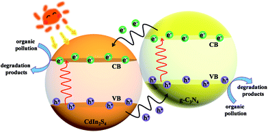 | ||
| Fig. 7 Possible mechanism of charge transfer in a CIS/CN heterojunction photocatalyst under visible-light irradiation. | ||
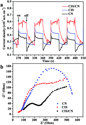
In order to support the abovementioned mechanism, the relative charge recombination efficiency of CIS, CN and CIS/CN has been studied using transient photocurrent responses and Nyquist plot of EIS. As shown in Fig. 8a, after four on–off cycles, the generation of photocurrent exhibits good reproducibility with stable photocurrent intensity for all samples. It can be known from the data that the photocurrent of the CIS/CN electrode is about 2.1 times and 1.7 times higher than that of CIS and CN electrodes, respectively, which indicates that an enhanced photoinduced electrons and holes separation could be caused by the formation of heterojunction structure. These results also could be confirmed by the Nyquist plots of EIS. Owing to the radius of the arc on the EIS Nyquist plot reports the charge transfer rate occurring at the contact interface between the working electrode and electrolyte solution, the smaller arc radius suggests the higher efficiency of photoinduced charge transfer.35 As shown in Fig. 8b, CIS/CN exhibits the smaller radius of arc, which demonstrates that the heterojunction structure is beneficial to improve the charge transfer efficiency. Both transient photocurrent responses and EIS Nyquist plots can further account for the better photocatalytic performance of CIS/CN and confirm the possible mechanism of charge transfer in CIS/CN.
Conclusions
In summary, heterojunction photocatalysts composed of CIS nanocrystals and CN nanosheets have been prepared via a two-steps wet chemistry approach. The formation of a heterojunction structure and strong interface interaction between CIS and CN were characterized by XPS spectra, and they could efficiently enhance the photogenerated charge transfer and suppress the recombination of electrons and holes, which also have been demonstrated by the transient photocurrent responses and Nyquist plots of EIS. The as-prepared photocatalysts exhibited enhanced photocatalytic activity than pristine CIS and CN. The reaction rate constant k in photocatalytic degradation of MO is about 3.19 times and 5.24 times higher than pure CIS and CN, respectively. The CIS/CN also showed excellent photocatalytic performance in degradation of TC. Moreover, the CIS/CN heterojunction photocatalysts exhibited good photocatalytic stability and reusability, which are very important index for the practical application of photocatalyst.Acknowledgements
This study was financially supported by the National Natural Science Foundation of China (Grants 21606111, 21406091, 21477050), the Natural Science Foundation of Jiangsu Province (BK20140530 and BK20150482), the China Postdoctoral Science Foundation (2015M570409), the Chinese-German Cooperation Research Project (GZ1091), the Program for High-Level Innovative and Entrepreneurial Talents in Jiangsu Province, Program for New Century Excellent Talents in University (NCET-13-0835), the Henry Fok Education Foundation (141068) and the Six Talents Peak Project in Jiangsu Province (XCL-025).Notes and references
- J. Z. Chen, X. J. Wu, L. S. Yin, B. Li, X. Hong, Z. X. Fan, B. Chen, C. Xue and H. Zhang, Angew. Chem., Int. Ed., 2014, 53, 1–6 CrossRef
.
- L. D. Li, J. Q. Yan, T. Wang, Z. J. Zhao, J. Zhang, J. L. Gong and N. J. Guan, Nat. Commun., 2015, 6, 5881 CrossRef PubMed
.
- C. Han, Z. Chen, N. Zhang, J. C. Colmenares and Y. J. Xu, Adv. Funct. Mater., 2015, 25, 221–229 CrossRef CAS
.
- X. C. Wang, K. Maeda, A. Thomas, K. Takanabe, G. Xin, J. M. Carlsson, K. Domen and M. Antonietti, Nat. Mater., 2009, 8, 76–80 CrossRef CAS PubMed
.
- X. H. Li, J. S. Chen, X. C. Wang, J. H. Sun and M. Antonietti, J. Am. Chem. Soc., 2011, 133, 8074–8077 CrossRef CAS PubMed
.
- W. J. Ong, L. L. Tan, Y. H. Ng, S. T. Yong and S. P. Chai, Chem. Rev., 2016, 116, 7159–7329 CrossRef CAS PubMed
.
- H. J. Yu, L. Shang, T. Bian, R. Shi, G. I. N. Waterhouse, Y. F. Zhao, C. Zhou, L. Z. Wu, C. H. Tung and T. R. Zhang, Adv. Mater., 2016, 28, 5080–5086 CrossRef CAS PubMed
.
- F. Dong, Z. W. Zhao, Y. J. Sun, Y. X. Zhang, S. Yan and Z. B. Wu, Environ. Sci. Technol., 2015, 49, 12432–12440 CrossRef CAS PubMed
.
- D. L. Jiang, J. Li, C. S. Xing, Z. Y. Zhang, S. C. Meng and M. Chen, ACS Appl. Mater. Interfaces, 2015, 7, 19234–19242 CAS
.
- Y. F. Li, R. X. Jin, Y. Xing, J. Q. Li, S. Y. Song, X. C. Liu, M. Li and R. C. Jin, Adv. Energy Mater., 2016, 1601273 CrossRef
.
- X. F. Yang, Z. P. Chen, J. S. Xu, H. Tang, K. M. Chen and Y. Jiang, ACS Appl. Mater. Interfaces, 2015, 7, 15285–15293 CAS
.
- J. Ran, T. Y. Ma, G. Gao, X. W. Du and S. Z. Qiao, Energy Environ. Sci., 2015, 8, 3708–3717 CAS
.
- H. J. Kong, H. W. Da, J. Kim and S. I. Woo, Chem. Mater., 2016, 28, 1318–1324 CrossRef CAS
.
- D. L. Jiang, T. Y. Wang, Q. Xu, D. Li, S. C. Meng and M. Chen, Appl. Catal., B, 2017, 201, 617–628 CrossRef CAS
.
- R. R. Hao, G. H. Wang, H. Tang, L. L. Sun, C. Xu and D. Y. Han, Appl. Catal., B, 2016, 187, 47–58 CrossRef CAS
.
- F. T. Lia, Y. Zhao, Q. Wang, X. J. Wang, Y. J. Hao, R. H. Liu and D. S. Zhao, J. Hazard. Mater., 2015, 283, 371–381 CrossRef PubMed
.
- F. T. Li, S. J. Liu, Y. B. Xue, X. J. Wang, Y. J. Hao, J. Zhao, R. H. Liu and D. S. Zhao, Chem.–Eur. J., 2015, 21, 10149–10159 CrossRef CAS PubMed
.
- X. J. Wang, Q. Wang, F. T. Li, W. Y. Yang, Y. Zhao, Y. J. Hao and S. J. Liu, Chem. Eng. J., 2013, 234, 361–371 CrossRef CAS
.
- X. J. Wang, W. Y. Yang, F. T. Li, Y. B. Xue, R. H. Liu and Y. J. Hao, Ind. Eng. Chem. Res., 2013, 52, 17140–17150 CrossRef CAS
.
- Z. Y. Zhang, D. L. Jiang, D. Li, M. Q. He and M. Chen, Appl. Catal., B, 2016, 183, 113–123 CrossRef CAS
.
- H. F. Shi, G. Q. Chen, C. L. Zhang and Z. G. Zou, ACS Catal., 2014, 4, 3637–3643 CrossRef CAS
.
- D. L. Jiang, L. L. Chen, J. M. Xie and M. Chen, Dalton Trans., 2014, 43, 4878–4885 RSC
.
- H. Liu, Z. Z. Xu, Z. Zhang and D. Ao, Appl. Catal., A, 2016, 518, 150–157 CrossRef CAS
.
- Y. S. Xu and W. D. Zhang, ChemCatChem, 2013, 5, 2343–2351 CrossRef CAS
.
- C. C. Han, L. Ge, C. F. Chen, Y. J. Li, X. L. Xiao, Y. N. Zhang and L. L. Guo, Appl. Catal., B, 2014, 147, 546–553 CrossRef CAS
.
- Y. L. Tian, B. B. Chang, J. L. Lu, J. Fu, F. N. Xi and X. P. Dong, ACS Appl. Mater. Interfaces, 2013, 5, 7079–7085 CAS
.
- D. Li, X. C. Duan, Q. Qin, H. M. Fan and W. J. Zheng, J. Mater. Chem. A, 2013, 1, 12417–12421 CAS
.
- B. B. Kale, J. O. Baeg, S. M. Lee, H. Chang, S. J. Moon and C. W. Lee, Adv. Funct. Mater., 2006, 16, 1349–1354 CrossRef CAS
.
- D. Li, W. D. Shi and W. J. Zheng, J. Cryst. Growth, 2016, 448, 93–96 CrossRef CAS
.
- Y. H. Ao, K. D. Wang, P. F. Wang, C. Wang and J. Hou, Appl. Catal., B, 2016, 194, 157–168 CrossRef CAS
.
- S. Q. Guo, M. M. Zhen, M. Q. Sun, X. Zhang, Y. P. Zhao and L. Liu, RSC Adv., 2015, 5, 16376–16385 RSC
.
- D. Li, Q. Qin, X. C. Duan, J. Q. Yang, W. Guo and W. J. Zheng, ACS Appl. Mater. Interfaces, 2013, 5, 9095–9100 CAS
.
- N. Liang, J. T. Zai, M. Xu, Q. Zhu, X. Wei and X. F. Qian, J. Mater. Chem. A, 2014, 2, 4208–4216 CAS
.
- X. L. Fu, W. M. Tang, L. Ji and S. F. Chen, Chem. Eng. J., 2012, 180, 170–177 CrossRef CAS
.
- D. M. Chen, K. W. Wang, D. G. Xiang, R. L. Zong, W. Q. Yao and Y. F. Zhu, Appl. Catal., B, 2014, 147, 554–561 CrossRef CAS
.
| This journal is © The Royal Society of Chemistry 2017 |

