 Open Access Article
Creative Commons Attribution 3.0 Unported Licence
Novel synthesis of dual-suspended architectures between Si-pillars for enhanced photocatalytic performance†
Yu Sun‡
a,
Rui Chen‡b,
Jihyeon Oha,
Bongyoung Yoo*a and
Haiwon Lee*b
aDepartment of Materials Engineering, Hanyang University, Ansan, Gyeonggi-do 15588, Korea. E-mail: byyoo@hanyang.ac.kr
bDepartment of Chemistry, Hanyang University, Seoul, 04763, Korea. E-mail: haiwon@hanyang.ac.kr
First published on 12th January 2017
Abstract
A facile approach is developed to synthesize a dual-suspended architecture, in which 3D carbon nanotube (CNT) networks are first bridged between Si pillars through a catalyzed method and suspended oxide architectures are subsequently synthesized on CNT networks through pulse electrodeposition. These dual-suspended structures show excellent photocatalytic activity toward methylene blue (MB) photo-decomposition under visible light illumination.
Metal oxides are the most widely used materials in sensors, environmental pollution control, and energy conversion and storage.1–8 Among metal oxides, Cu2O has attracted a lot of attention as it is inexpensive, plentiful, environmentally friendly, and readily available. Furthermore, Cu2O is a p-type semiconductor with a direct bandgap of 2.0–2.2 eV, which has been studied previously for applications in solar energy converting devices, antifouling coatings, water splitting, and other photocatalytic reactions.9–15 It was documented that the catalytic abilities of catalysts are strongly influenced by surface electronic structures, which partially rely on their morphologies and exposed surface area. In our previous work, we electrochemically deposited Cu2O on Ti/Au/Si wafer substrates as photocatalysts.16 However, the photocatalytic abilities were limited due to the insufficient exposure of photocatalysts. Therefore, we hypothesised that the growth of suspended Cu2O would significantly increase the exposed surface area of catalysts and further enhance the catalytic properties.
Previously, numerous different kinds of materials have been studied to produce artificial networks. Among these materials, CNTs are considered as the most suitable candidates because of their excellent chemical, mechanical, and electrical properties.17–19 Therefore, in this work, CNT networks were employed as nano-substrates, on which the preparation of metal oxide architectures was carried out through pulse electrodeposition, forming dual-suspended architectures for enhanced photocatalytic performance.
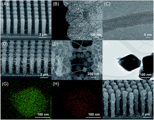
As illustrated in Scheme 1, we first fabricated CNT networks as bridging materials for the growth of a suspended metal oxide architecture between Si pillars (abbreviated to SiP) using a low-pressure thermal chemical vapor deposition (LPTCVD) method20,21 (abbreviated CNT–SiP). Then, Cu2O was pulse electrodeposited by using CNT–SiP as a working electrode, as described in a previous report.22–24 The details are shown in the ESI.† As shown in Fig. 1(A), CNT networks were massively synthesized between Si pillars. CNTs were also found around each Si pillar as the CNT growth started on the Si pillar substrates. TEM images of CNTs further confirmed the successful synthesis of carbon nanotube structures with an average width of ∼14 nm, as shown in Fig. 1(B) and (C). To prepare a suspended Cu2O architecture on CNT networks (abbreviated Cu–CNT–SiP), pulse electrodeposition was carried out by taking CNT–SiP as a working electrode in a mixed solution containing 0.01 M cupric acetate and 0.1 M sodium acetate. As shown in Fig. 1(D), a large quantity of octahedral and quasi-octahedral structures penetrated by CNTs was successfully synthesized. The high-magnification SEM image (Fig. 1(E)) and TEM image (Fig. 1(F)) indicate that the average size of the diagonal line of (quasi-)octahedron structures was ∼100–200 nm. The elemental mapping analysis suggested the presence of Cu (Fig. 1(G)) and O (Fig. 1(H)) components in the suspended (quasi-)octahedral structures. Interestingly, we found that the successful synthesis of suspended architecture on CNT networks through pulse electrodeposition probably relies on the electrical conductivity of the Si-pillar substrate. When we used highly-doped Si-pillar samples, a large amount of oxides was formed on the top of the Si pillar (Fig. 1(I)), and only a trace amount of suspended architectures was synthesized on the CNT networks.
 | ||
| Scheme 1 Graphic illustration of each step for the preparation of suspended cuprous oxide (Cu2O) architecture. | ||
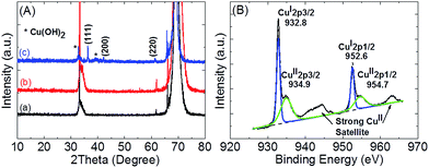
To identify the microstructure of suspended (quasi-)octahedron structures, X-ray diffraction (XRD) measurements were carried out for all samples. As shown in Fig. 2(A), diffraction peaks of the Cu–CNT–SiP sample (blue line) at 2θ = 36.8, 42.1, and 61.2 were not observed for SiP (black line) or CNT–SiP (red line) samples. These diffraction peaks can be indexed to face centered cubic phase Cu2O (JCPDS 77-0199),25 which confirmed that the suspended (quasi-)octahedron structures mainly composed of cuprous oxides. Furthermore, additional diffraction peaks were observed at 2θ = 32.4 and 38.6, which probably belong to either CuO or Cu(OH)2.
 | ||
| Fig. 2 (A) X-ray diffraction patterns of (a) SiP, (b) CNT–SiP, and (c) Cu–CNT–SiP; (B) XPS analysis of Cu element for Cu–CNT–SiP immediately after preparation. | ||
It has been reported that Cu2O (rather than CuO) can be synthesized under our employed conditions.24,26 Nevertheless, Cu(OH)2 is normally synthesized as a side product when changing the electrodeposition potential.27 Therefore, further confirmation of the composition was conducted using X-ray photoelectron spectroscopy (XPS). As shown in Fig. 2(B), a sharp and symmetric XPS peak, which corresponded to the CuI 2p3/2 of Cu2O, was observed at 932.8 eV. A shoulder peak at 934.9 eV corresponding to CuII 2p3/2 of Cu(OH)2 together with strong CuII satellite peaks were also clearly observed, indicating that additional XRD peaks actually came from Cu(OH)2 instead of CuO because the CuII 2p3/2 peak of CuO is normally located at ∼933.4 eV. To confirm the stability of Cu–CNT–SiP, we placed our samples in air for 1 month without any treatment and carried out XPS measurements. As shown in Fig. S2,† no significant difference was found when comparing XPS data with those measured for as-prepared samples. These results revealed that our samples have good stability in air, and that no CuO was formed either during the electrodeposition process or upon exposure to air.
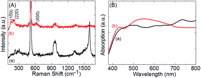
Furthermore, these 3D hierarchical networks were investigated using Raman spectroscopy to understand the formation of CNTs around the patterned Si pillars and the formation of suspended metal oxide architectures on CNTs networks. As shown in Fig. 3(A), the Raman spectra of CNT–SiP showed two unique Raman bands at ∼1350 and 1590 cm−1, which were in good agreement with the well-known D and G bands of typical CNTs, respectively.17–19 These results indicate that the initial nano-networks were constructed of CNTs bridging between Si pillars. After the electrochemical synthesis of the suspended oxide architecture, both the D and G bands were significantly weakened, but did not disappear. In a previous report, metal oxide-coated CNT networks were synthesized through an electrodeposition method, in which neither D nor G bands were detected after coating.27 This suggests that our approach provided a suspended oxide architecture instead of fully coated samples. Raman scattering is another useful tool to distinguish different oxide species. Group theoretical calculations have shown that Cu2O has six zone-center optical phonon modes.28–30 Unfortunately, the Raman-active mode F2g at 520 cm−1 was covered by a strong Si Raman signal and therefore could not be visually distinguished. Two IR active modes F1u at 150 and 630 cm−1 and overtone 2Eu at 220 cm−1 were clearly observed. The mode at 415 cm−1 due to a multiphoton process was quite weak in our case. However, the characteristic optical phonon modes for CuO were not observed in our samples.31–33 These results, which are in accordance with XRD and XPS data, further confirmed that Cu2O was the dominant component in the suspended metal oxide architecture. Subsequently, UV-vis absorption spectra were measured for both CNT–SiP and Cu–CNT–SiP samples. These results clearly showed that the visible light absorption in the range of 450 nm to 680 nm was enhanced due to the formation of the suspended oxide architectures (Fig. 3(B)).
 | ||
| Fig. 3 (A) Raman spectra of (a) CNT–SiP and (b) Cu–CNT–SiP; (B) UV-vis spectra of (a) CNT–SiP and (b) Cu–CNT–SiP. | ||
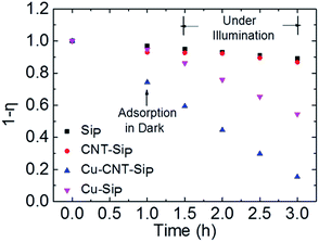
The photocatalytic degradation of MB dye as a function of time in the presence of Cu–CNT–SiP was determined by measuring the UV-vis absorption spectra (Fig. S3 (A)†). For a better comparison, MB decomposition was investigated with SiP (Fig. S3(B)†), CNT–SiP (Fig. S3(C)†), and with a non-suspended architecture (abbreviated as Cu–SiP, Fig. S3(D)†). Details related to the preparation of Cu–SiP are shown in the ESI.† The photocatalytic reaction of the MB dye was performed by putting our sample in MB dye solution (10 ppm) under visible light illumination for 2 h. Before light illumination, samples were kept in the MB solution for 1 h in the dark to reach adsorption equilibrium. We found that both SiP and CNT–SiP had weak photocatalytic abilities towards MB decomposition under visible light illumination. However, the latter had better adsorption ability, probably due to the formation of CNT networks. In contrast, both Cu–SiP and Cu–CNT–SiP presented a gradual and steady decrease in the absorption peak formed at λmax = 664 nm. The percentage of dye degradation, η, was calculated as follows:
To visually compare the photocatalytic properties, the percentage of dye residue (1 − η) was plotted against the reaction time (Fig. 4). The value of (1 − η) after 1 h of adsorption equilibrium in the dark was calculated for all samples. These results showed that our suspended oxide architecture (Cu–CNT–SiP) had a strong adsorption ability, in that 28% of MB dye was removed within 1 h. After 2 h of photocatalytic reactions, no significant MB degradation was observed for SiP and CNT–SiP, and only 46% of the MB dye was totally removed by Cu–SiP. However, Cu–CNT–SiP with suspended metal oxide architectures was extremely effective for MB decomposition, removing a total of 86% of the MB after 2 h of the photocatalytic reaction.
We provided the first demonstration of a facile approach to synthesize a dual-suspended architecture. The CNT network that bridges between patterned Si pillars was first synthesized by LPTCVD. Nanometer-sized octahedron and quasi-octahedron structures of cuprous oxide were synthesized on CNT networks through pulse electrodeposition, as confirmed by XRD, XPS, and Raman spectroscopy. The as-synthesized samples, Cu–CNT–SiP, showed excellent photocatalytic abilities towards MB decomposition under visible light illumination, and 86% of MB dye was removed within 2 h. To the best of our knowledge, the controlled synthesis of suspended architectures on suspended substrates (here, CNT networks) by the electrodeposition process has seldom been documented. Our findings offered a facile and rational method for the designed synthesis of dual-suspended architectures. However, we believe that an investigation of the associated growth mechanisms can facilitate a deep understanding of designed materials synthesis, which will be a focus of the follow-up experiments.
Acknowledgements
The authors thank the National Research Foundation of Korea and Ministry of Science, ICT and Future Planning for financial support (2012M3A7B4035286, 2012R1A6A1029029, 2015R1A5A1037548, 2016K1A4A3914691 and IITP2016R0992161021). Yu Sun and Rui Chen contributed equally to this work.References
- A. S. Arico, P. Bruce, B. Scrosati, J. M. Tarascon and W. Van Schalkwijk, Nat. Mater., 2005, 4, 366–377 CrossRef CAS PubMed.
- Y. G. Guo, J. S. Hu and L. J. Wan, Adv. Mater., 2008, 20, 2878–2887 CrossRef CAS.
- M. C. Toroker and E. A. Carter, J. Mater. Chem. A, 2013, 1, 2474–2484 CAS.
- Y. Sekine, Atmos. Environ., 2002, 36, 5543–5547 CrossRef CAS.
- M. Miyauchi, A. K. Nakajima, T. Watanabe and K. Hashimoto, Chem. Mater., 2002, 14, 4714–4720 CrossRef CAS.
- N. Talebian and M. R. Nilforoushan, Thin Solid Films, 2010, 518, 2210–2215 CrossRef CAS.
- H. Meixner, J. Gerblinger, U. Lampe and M. Fleischer, Sens. Actuators, B, 1995, 23, 119–125 CrossRef CAS.
- N. Barsan, D. Koziej and U. Weimar, Sens. Actuators, B, 2007, 121, 18–35 CrossRef CAS.
- B. P. Rai, Sol. Cells, 1988, 25, 265–272 CrossRef CAS.
- L. C. Olsen, F. W. Addis and W. Miller, Sol. Cells, 1982, 7, 247–279 CrossRef CAS.
- S. Kiil, K. Dam-Johansen, C. E. Weinell, M. S. Pedersen and S. A. Codolar, Biofouling, 2003, 19, 37–43 CrossRef CAS PubMed.
- S. Kiil and K. Dam-Johansen, Prog. Org. Coat., 2007, 60, 238–247 CrossRef CAS.
- P. E. de Jongh, D. Vanmaekelbergh and J. J. Kelly, Chem. Commun., 1999, 1069–1070, 10.1039/a901232j.
- M. Hara, T. Kondo, M. Komoda, S. Ikeda, K. Shinohara, A. Tanaka, J. N. Kondo and K. Domen, Chem. Commun., 1998, 357–358, 10.1039/a707440i.
- Z. K. Zheng, B. B. Huang, Z. Y. Wang, M. Guo, X. Y. Qin, X. Y. Zhang, P. Wang and Y. Dai, J. Phys. Chem. C, 2009, 113, 14448–14453 CAS.
- S. Yoon, M. Kim, I. S. Kim, J. H. Lim and B. Yoo, J. Mater. Chem. A, 2014, 2, 11621–11627 CAS.
- S. F. Zheng, J. S. Hu, L. S. Zhong, W. G. Song, L. J. Wan and Y. G. Guo, Chem. Mater., 2008, 20, 3617–3622 CrossRef CAS.
- B. You, L. L. Wang, L. Yao and J. Yang, Chem. Commun., 2013, 49, 5016–5018 RSC.
- E. Unger, G. S. Duesberg, M. Liebau, A. P. Graham, R. Seidel, F. Kreupl and W. Hoenlein, Appl. Phys. A: Mater. Sci. Process., 2003, 77, 735–738 CrossRef CAS.
- J. Seo, T. J. Lee, S. Ko, H. Yeo, S. Kim, T. Noh, S. Song, M. M. Sung and H. Lee, Adv. Mater., 2012, 24, 1975–1979 CrossRef CAS PubMed.
- J. Seo, T. J. Lee, C. Lim, S. Lee, C. Rui, D. Ann, S. B. Lee and H. Lee, Small, 2015, 11, 2990–2994 CrossRef CAS PubMed.
- L. K. Tsui, L. L. Wu, N. Swami and G. Zangari, ECS Electrochem. Lett., 2012, 1, D15–D19 CrossRef CAS.
- S. Tao and D. Y. Li, Nanotechnology, 2006, 17, 65–78 CrossRef CAS.
- Y. E. Gu, X. Su, Y. L. Du and C. M. Wang, Appl. Surf. Sci., 2010, 256, 5862–5866 CrossRef CAS.
- S. Kumar, C. M. A. Parlett, M. A. Isaacs, D. V. Jowett, R. E. Douthwaite, M. C. R. Cockett and A. F. Lee, Appl. Catal., B, 2016, 189, 226–232 CrossRef CAS.
- N. Fredj and T. D. Burleigh, J. Electrochem. Soc., 2011, 158, C104–C110 CrossRef CAS.
- K. G. Lee, S. Lee, S. J. Chang, B. G. Choi, J. Seo, A. Sangalang, D. H. Kim, T. J. Park, M. K. Lee, S. J. Lee and H. Lee, Small, 2015, 11, 4292–4297 CrossRef CAS PubMed.
- A. Singhal, M. R. Pai, R. Rao, K. T. Pillai, I. Lieberwirth and A. K. Tyagi, Eur. J. Inorg. Chem., 2013, 2640–2651, DOI:10.1002/ejic.201201382.
- K. Huang, Z. Phys., 1963, 171, 213–225 CrossRef CAS.
- P. Dawson, M. M. Hargreave and G. R. Wilkinson, J. Phys. Chem. Solids, 1973, 34, 2201–2208 CrossRef CAS.
- W. Z. Wang, L. J. Wang, H. L. Shi and Y. J. Liang, CrystEngComm, 2012, 14, 5914–5922 RSC.
- J. F. Xu, W. Ji, Z. X. Shen, W. S. Li, S. H. Tang, X. R. Ye, D. Z. Jia and X. Q. Xin, J. Raman Spectrosc., 1999, 30, 413–415 CrossRef CAS.
- W. Z. Wang, Q. Zhou, X. M. Fei, Y. B. He, P. C. Zhang, G. L. Zhang, L. Peng and W. J. Xie, CrystEngComm, 2010, 12, 2232–2237 RSC.
Footnotes |
| † Electronic supplementary information (ESI) available. See DOI: 10.1039/c6ra25464k |
| ‡ Y. Sun and R. Chen contributed equally to this work. |
| This journal is © The Royal Society of Chemistry 2017 |


