 Open Access Article
Creative Commons Attribution 3.0 Unported Licence
3D urchin-like black TiO2−x/carbon nanotube heterostructures as efficient visible-light-driven photocatalysts
Yuchi Zhanga,
Zipeng Xing*a,
Jinlong Zoua,
Zhenzi Lib,
Xiaoyan Wub,
Liyan Shena,
Qi Zhua,
Shilin Yang*a and
Wei Zhou*a
aDepartment of Environmental Science, School of Chemistry and Materials Science, Key Laboratory of Functional Inorganic Material Chemistry, Ministry of Education of the People's Republic of China, Heilongjiang University, Harbin 150080, P. R. China. E-mail: xzplab@163.com; ysl3000@126.com; zwchem@hotmail.com; Fax: +86-451-8660-8240; Tel: +86-451-8660-8616
bDepartment of Epidemiology and Biostatistics, Harbin Medical University, Harbin 150086, P. R. China
First published on 3rd January 2017
Abstract
3D urchin-like black TiO2−x/CNT heterostructures are successfully fabricated via a facile one-pot solvothermal reaction combined with a subsequent in situ solid-state chemical reduction approach. The as-prepared photocatalysts are characterized in detail via X-ray diffraction, Raman spectroscopy, Fourier transform infrared spectroscopy, scanning electron microscopy, transmission electron microscopy, X-ray photoelectron spectroscopy and UV-vis diffuse reflectance spectroscopy. The results demonstrate that the obtained black TiO2−x/CNT heterostructures exhibit a 3D urchin-like heterojunction structure, and Ti3+ is doped into the lattice of anatase TiO2. This unique 3D structure with abundant active sites can enhance light scattering capability, and the Ti3+ self-doping defective TiO2 with a narrow bandgap can promote visible-light photocatalytic activity. Therefore, the TiO2−x/CNT heterostructures exhibit unparalleled high visible-light-driven photocatalytic activity and electrochemical properties. The visible-light-driven photocatalytic degradation rate for methylene orange is up to 99.6% and the hydrogen production rate is as high as 242.9 μmol h−1 g−1, which is ascribed to the 3D urchin-like structure offering abundant active sites, the heterostructures resulting in the separation of photogenerated charge carriers, and the Ti3+ self-doping narrowing the bandgap and favoring visible light absorption.
Introduction
In recent years, photocatalytic technology has aroused much interest due to its application in the degradation of organic pollutants, production of hydrogen, and reduction of CO2 to renewable hydrocarbon solar fuels.1–3 In addition, capacitors, lithium ion batteries and solar cells are being researched to solve the energy shortage.4,5 Among the myriad of photocatalytic materials, TiO2, which is one of the most suitable photocatalysts, has received widespread attention due to its low cost, innocuity, good stability and commercial availability.6–8 Nevertheless, the unavoidable disadvantages of TiO2 photocatalysts include being limited to the ultraviolet region of the absorption spectrum and rapid recombination of photogenerated electron–hole pairs.9,10 These issues lead to low solar-light utilization by TiO2 and reduce the photo-induced redox reaction.11,12 Thus the key factor to preparing highly active TiO2 is to enhance its visible-light energy conversion and suppress photogenerated electron–hole pairs recombination.In order to enhance TiO2 activity in the visible light region, different methods can be employed, including modification with transition metal additives, non-metals, rare earth metals, self-doping and sensitizers or combination with other semiconductors, etc.13–15 Defects in materials often show prominent effects that could lead to substantial advancement in the scientific field.16,17 Recently, structurally defective TiO2 with Ti3+ self-doping has been developed to expand its absorbance in the visible-light region.18–21 Mao et al.22 presented an innovative method to prepare TiO2 with Ti3+ self-doping using the high pressure hydrogenation of TiO2 nanocrystals. The as-prepared hydrogenated TiO2 was successful in narrowing the bandgap and enhancing photocatalytic activities. Subsequently, various researches are dedicated to this field. Several synthetic methods have been reported, such as high temperature, high pressure, hydrogenation,23,24 plasma treatment,25,26 and vacuum activation.27,28 However, these harsh and costly methods are less suitable for practical application. Therefore, a simple synthesis is required to produce TiO2 with Ti3+ self-doping under milder experimental conditions and within shorter reaction times, in order to improve photocatalytic performances.
Coupling TiO2 with other materials to form heterojunction structures is also an effective strategy to promote its photocatalytic activity. Carbon nanotubes (CNT) are one of the numerous studied materials with the benefits of large surface areas, high conductivity, high chemical stability, high tensile strength, and unique one-dimensional (1D) structure.29,30 At present, the reported synthetic methods for TiO2/CNT composites are chemical vapour deposition, sol–gel, and the hydrothermal method, etc.31–34 The application of TiO2/CNT composites demonstrates the advantages of both materials, the photocatalytic activity of TiO2, adsorption capacities of CNT and response of the prepared composites under visible-light irradiation. In addition, as 1D tubular structures, CNT can be synergized with TiO2 nanoparticles to form a highly entangled three-dimensional (3D) urchin-like structure, which favors various technological applications including optical, electronic, and catalytic properties, because it results in more abundant active sites to enhance light trapping and scattering ability compared to what can be achieved with 1D and 2D nanostructured materials. Therefore, this type of system has been further researched in order to enhance the performance of photocatalysts.35,36
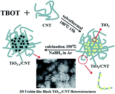
In this study, 3D urchin-like black TiO2−x/CNT heterojunctions are synthesized via a simple and effective one-pot solvothermal reaction combined with a subsequent in situ solid-state chemical reduction approach. The photocatalytic and electrochemical properties of the prepared photocatalyst have been proven by the photocatalytic degradation of a contaminant, photocatalytic hydrogen evolution and electrochemical measurements. In addition, the possible photocatalytic mechanism of the 3D urchin-like black TiO2−x/CNT heterojunctions is also proposed. Moreover, we believe that this effort will stimulate further research in the photocatalytic field in the near future.
Experimental
Material synthesis
![[thin space (1/6-em)]](https://www.rsc.org/images/entities/char_2009.gif) :
:![[thin space (1/6-em)]](https://www.rsc.org/images/entities/char_2009.gif) 3, each at the concentration of 5 M, under reflux at 100 °C for 180 min. Subsequently, 0.1 g of acid-treated CNT was dispersed in 50 mL of dehydrated alcohol with sonication for 30 min, and then 10 mL of glycerol and 1 mL of tetrabutyl titanate (TBT) were added into the prepared solution and gently stirred for 10 min. The mixture was then transferred to a 100 mL Teflon-lined stainless steel autoclave and kept in an electric oven at 180 °C for 15 h. The resulting powder was washed with ethanol and dried at 60 °C overnight, followed by calcination at 450 °C in air for 120 min, which is denoted as TiO2/CNT.
3, each at the concentration of 5 M, under reflux at 100 °C for 180 min. Subsequently, 0.1 g of acid-treated CNT was dispersed in 50 mL of dehydrated alcohol with sonication for 30 min, and then 10 mL of glycerol and 1 mL of tetrabutyl titanate (TBT) were added into the prepared solution and gently stirred for 10 min. The mixture was then transferred to a 100 mL Teflon-lined stainless steel autoclave and kept in an electric oven at 180 °C for 15 h. The resulting powder was washed with ethanol and dried at 60 °C overnight, followed by calcination at 450 °C in air for 120 min, which is denoted as TiO2/CNT.Characterization
X-ray diffraction (XRD) (Bruker D8 Discover) with a Cu K radiation wavelength of 1.54056 nm was used to determine the crystallographic properties of the nanocomposites. Raman measurements were performed with a Jobin Yvon HR 800 micro-Raman spectrometer at 457.9 nm. Fourier transform infrared spectra (FT-IR) of the samples, with KBr as diluents, were collected with a PerkinElmer Spectrum One system. Field-emission scanning electron microscopy (FE-SEM, Hitachi SU8010) was employed to observe the surface morphology of the ternary nanocomposites. Transmission electron microscopy (TEM) on a JEOL JEM-2010 at an accelerating voltage of 200 kV was applied to record electron micrographs of the samples. X-ray photoelectron spectroscopy (XPS) was carried out on a PHI-5700 ESCA with an Al Kα X-ray source. All binding energies were calibrated with surface adventitious carbon of 284.6 eV. UV-vis diffuse reflectance spectra (DRS) were obtained on a TU-1901 spectrophotometer using BaSO4 as the background over the range of 190–800 nm.Photocatalytic degradation
The liquid phase photodegradation of methyl orange (MO) was used as a probe to evaluate the catalytic performance of the samples and activity tests were carried out at room temperature in air. Before the photocatalytic reaction, 0.05 g samples were dispersed in 50 mL MO (10 mg L−1) aqueous solution and magnetically stirred for 30 min in dark to achieve adsorption equilibrium. Then, the solution was placed in a 100 mL cylindrical quartz reactor equipped with a water circulation facility under visible-light irradiation. A 300 W xenon lamp with a cut-off filter (λ ≥ 420 nm) served as a visible-light source. At regular irradiation time intervals, the suspension liquid was sampled (5 mL) and centrifuged to separate the suspended catalyst. MO concentration was monitored using a UV-vis spectrophotometer at its characteristic wavelength (λ = 554 nm), from which the degradation ratio could be calculated.Photocatalytic hydrogen evolution
Photocatalytic hydrogen evolution tests were carried out in an online photocatalytic hydrogen generation system (AuLight, Beijing, CEL-SPH2N) at room temperature. With Pt as the co-catalyst and 20 mL of methanol sacrificial agent, using a magnetic stirrer, 50 mg of photocatalysts were mixed with 80 mL of deionized water in a closed-gas circulation reaction cell. Prior to the reaction, the system was vacuumized completely to remove O2 and CO2 dissolved in water. Subsequently, the mixture solution was irradiated by a 300 W Xeon-lamp with a 420 nm cut-off filter. Using an on-line gas chromatograph, the hydrogen was periodically analyzed at an interval of 1 h (SP7800, TCD, molecular sieve 5 Å, N2 carrier, Beijing Keruida, Ltd).Electrochemical properties
The electrochemical properties of the catalysts were analyzed using the three-electrode cell configuration with a platinum counter electrode and standard calomel reference electrode at room temperature. An aqueous solution of 1 mol L−1 NaOH served as the electrolyte. An electrochemical workstation was employed to measure the photocurrent intensity of the samples under intermittent illumination with a 300 W Xe lamp (Perfectlife, PLS-SXE-300). The wavelength was over 300 nm and the irradiance was 176 mW cm−2, as measured by a radiometer (FZ-A, Photoelectric Instrument Factory of Beijing Normal University). Electrochemical impedance spectroscopic (EIS) measurements were performed between 100 kHz and 0.01 Hz at 0.05 V under illumination.Results and discussion
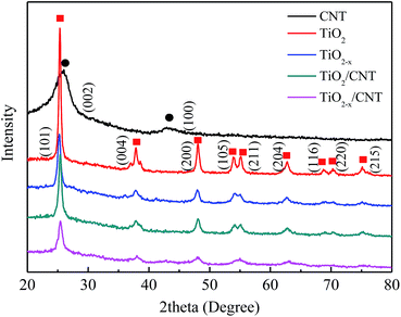
The X-ray diffraction patterns of the as-prepared samples are presented in Fig. 2. All the XRD patterns exhibit similar diffraction peaks except CNT, which appear at 25.3, 37.8, 48.1, 54.1, 54.9, 62.7, 68.9, 70.2, and 75.1. Compared with the standard pattern (JCPDS no. 21-1272), the as-prepared samples can be identified as anatase TiO2. The above perks correspond to the crystal planes of (101), (004), (200), (105), (211), (204), (116), (220), and (215).37 No characteristics peaks of CNT are found in the spectra of the composites in the range investigated. This may be attributed to the overlap of the intense peaks of the CNT (002) and anatase (001) reflections, and the difference in mass between CNT and TiO2 is relatively large.38 Moreover, TiO2−x/CNT still keeps the anatase TiO2 lattice plane after treatment with NaBH4, however the diffraction peaks are evidently broadened and their intensity decreases, which indicate that its crystalline structure has some variations. According to related reports, the change in crystalline structure may be ascribed to the production of Ti3+ and oxygen vacancies through the chemical reduction treatment.39Raman spectroscopy is another powerful tool to characterize both TiO2 and CNT. As shown in Fig. 3, the Raman spectra of the composite sample exhibit characteristic peaks of anatase TiO2 as well as the G- and D-bands of CNT. Four vibrational modes with strong intensities at 142 (Eg), 396 (B1g), 517 (B1g + A1g), and 639 cm−1 (Eg) are observed, which reveal that anatase is the predominant phase of the pure TiO2 particles.40 In addition, these peaks, although shift toward higher frequencies, also appear in the TiO2/CNT and the TiO2−x/CNT composites, and such changes can be reasonably attributed to the interaction between TiO2 and CNT.41 Two characteristic peaks appear in the composite and pure CNT at wavelengths of approximately 1353 and 1586 cm−1, which correspond to the disordered carbon (D band) and graphitic carbon (G band) of the CNT, respectively. Moreover, TiO2−x exhibits blue-shifting compared to the pure TiO2, and broadening and weakening of the Eg peak, which are attributed to the formation of Ti3+ and oxygen deficiencies in the TiO2 lattice,42 and are consistent with the XRD results.
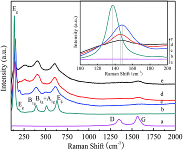 | ||
| Fig. 3 Raman spectra of CNT (a), TiO2 (b), TiO2−x (c), TiO2/CNT (d) and TiO2−x/CNT (e). The inset is the magnified Eg mode of the samples between 100–200 cm−1. | ||
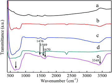
FT-IR was used to investigate the functional groups of the as-synthesized samples. Fig. 4 shows the IR spectra of the samples collected in the region of 400–4000 cm−1. All the samples present similar spectra in which a strong absorption peak appears in the range of 400–800 cm−1 except CNT, which can be mainly ascribed to the Ti–O–Ti flexion vibration.43 The signals in the region of 1400–1630 cm−1 in the hybrid confirm the presence of CNT and indicate that the polymer removal process does not produce any apparent damage to the CNT. The functional groups of C![[double bond, length as m-dash]](https://www.rsc.org/images/entities/char_e001.gif) C (1476 cm−1 and 1569 cm−1) and C
C (1476 cm−1 and 1569 cm−1) and C![[double bond, length as m-dash]](https://www.rsc.org/images/entities/char_e001.gif) O (1670 cm−1) were found in the prepared composite, which are the characteristic functional groups of CNT. Furthermore, the FT-IR peaks at about 3348 cm−1 are ascribed to the stretching vibrations of surface hydroxyl groups.44 The observed functional groups of TiO2 and CNT indicate that the hybrid structures were successfully obtained by the one-pot solvothermal reaction.
O (1670 cm−1) were found in the prepared composite, which are the characteristic functional groups of CNT. Furthermore, the FT-IR peaks at about 3348 cm−1 are ascribed to the stretching vibrations of surface hydroxyl groups.44 The observed functional groups of TiO2 and CNT indicate that the hybrid structures were successfully obtained by the one-pot solvothermal reaction.
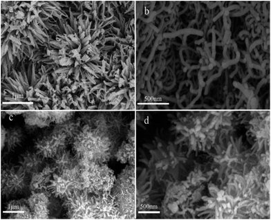
Fig. 5 shows SEM images of the samples. As shown in Fig. 5a, a 3D flower-liked structure is exhibited, which reflects the aggregation effect of pure TiO2. The surface morphology of the TiO2−x/CNT composites is shown in Fig. 5c and d. Pure CNT had a smooth surface and homogeneous dispersion (Fig. 5b), and the TiO2 nanoparticles were deposited over the surface of CNT. No individual and isolated TiO2 nanomaterial was evidently observed in the TiO2−x/CNT composite. Fig. 5c displays the highly entangled 3D urchin-like architecture formed by the synergistic effect of CNT and TiO2, and Fig. 5d reveals its surface morphology, which features the assembly of CNT in different angles with TiO2 nanoparticles. These well designed TiO2−x/CNT composites can greatly increase surface area, promote light scattering, and thus improve the photocatalytic performance.
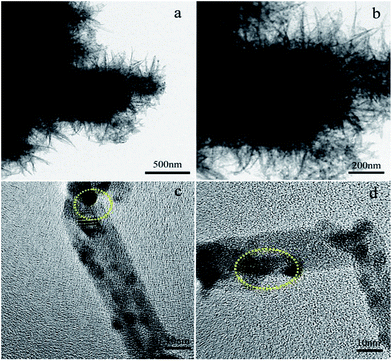
Transmission electron microscopy analysis was used to investigate the crystal structure and morphology of the samples. The TEM and HRTEM images of the TiO2−x/CNT composite are shown in Fig. 6. As shown in Fig. 6a and b, the 3D urchin-like structure is also exhibited, which is consistent with the SEM image. Fig. 6c and d show the HRTEM image of the TiO2−x/CNT composite structure. The high magnification image (Fig. 6c) discloses the lattice fringes of TiO2 and CNT. The lattice spacing of 0.35 nm obtained from the TiO2 nanoparticles is attributed to the crystal facet of (101).24 Moreover, the lattice spacing of 0.34 nm is identical to the facet of (002) of CNT. Fig. 6d shows TiO2 nanoparticles deposited on the tube wall of the CNT. The heterojunction of the CNT–TiO2 (highlighted area in Fig. 6d) can be visualized from the overlapping of the two different lattice fringes of CNT and TiO2. The CNT–TiO2 heterojunction would promote electron transfer and separation, thus promoting photocatalytic reactions.45
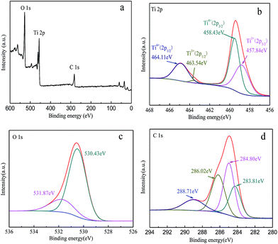
X-ray photoelectron spectroscopy was used to characterize the TiO2−x/CNT composite. The chemical state and surface composition of TiO2−x/CNT are shown in Fig. 7. Fig. 7a presents the full-scale XPS spectrum of TiO2−x/CNT, which indicates the existence of Ti, O and C elements. Fig. 7b presents the Ti 2p region, and the bands centered at 457.84, 458.43, 463.54 and 464.11 eV correspond to Ti3+ 2p3/2, Ti4+ 2p3/2, Ti3+ 2p1/2, and Ti4+ 2p1/2, respectively. Ti3+ species are created due to the Ti4+ reduction of TiO2 in the process of treatment with NaBH4. Fig. 7c presents the O 1s region, which is asymmetric and deconvoluted into two peaks. The main peak at 530.43 eV can be ascribed to lattice oxygen (O22−) in anatase TiO2, whereas the broad peak at 531.87 eV is assigned to C![[double bond, length as m-dash]](https://www.rsc.org/images/entities/char_e001.gif) O or Ti–O–C bonds.46 The corresponding C 1s spectrum in Fig. 7d can also be deconvoluted into four peaks. The peak at 283.81 eV can be ascribed to the sp2 carbon.47 The peak at 284.80 eV is attributed to adventitious carbon and sp3 carbon from CNT. The peaks at 286.02 and 288.71 eV correspond to O–C
O or Ti–O–C bonds.46 The corresponding C 1s spectrum in Fig. 7d can also be deconvoluted into four peaks. The peak at 283.81 eV can be ascribed to the sp2 carbon.47 The peak at 284.80 eV is attributed to adventitious carbon and sp3 carbon from CNT. The peaks at 286.02 and 288.71 eV correspond to O–C![[double bond, length as m-dash]](https://www.rsc.org/images/entities/char_e001.gif) O33,48 from the functional groups on CNT, which may act as the anchoring center for the nucleation of TiO2, thus forming O
O33,48 from the functional groups on CNT, which may act as the anchoring center for the nucleation of TiO2, thus forming O![[double bond, length as m-dash]](https://www.rsc.org/images/entities/char_e001.gif) C–Ti or C–O–Ti bands.
C–Ti or C–O–Ti bands.
The UV-vis diffuse reflectance spectra of the four investigated photocatalysts are shown in Fig. 8. As shown in Fig. 8a, the as-prepared TiO2−x sample exhibits a stronger absorption between 400–800 nm compared to pure TiO2. This strong absorption in the visible-light region is attributed to the existence of bulk Ti3+ defects, which induces a continuous vacancy band of electronic states just below the conduction band edge of TiO2−x. In addition, the light absorption of the TiO2/CNT composite is found to have a similar trend with that of the anatase TiO2, but at a magnified scale with absorption in the visible light range (400–800 nm). This observation suggests that modification of TiO2−x/CNT could provide efficient visible-light-driven photocatalytic activity, thus enhancing electron–hole pair generation under visible light irradiation, which further contributes to enhanced photocatalytic performance.31,49 Using the Kubelka–Munk function as the vertical axis against photon energy, as shown in Fig. 8b, the band gap of TiO2 and TiO2−x is 3.08 and 2.46, respectively. These results suggest that TiO2−x is more active with a narrower intrinsic band gap than the as-prepared TiO2 catalysts. Moreover, the narrow band gap is beneficial for visible-light-driven photocatalysis.
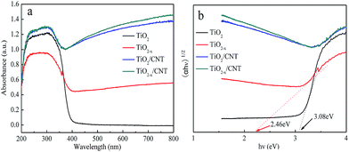 | ||
| Fig. 8 UV-vis spectra (a) with different samples, and determination of the indirect interband transition energies (b) for TiO2 and TiO2−x. | ||
The photocatalytic activity of different samples was evaluated by the photodegradation of MO degradation under visible-light irradiation and the results are shown in Fig. 9. For comparison, a blank experiment without the presence of a catalyst was performed under visible-light irradiation. As shown in Fig. 9a, the self-degradation process by only 1.12% degraded MO can be neglected after 150 min of visible-light irradiation. After 30 min of dark adsorption equilibrium, the initial MO can be removed by 8.9%, 9.8%, 52.5%, and 53.9% with TiO2, TiO2−x, TiO2/CNT, and TiO2−x/CNT, respectively. These results show the excellent adsorption properties of CNT. In comparison to pure TiO2, TiO2−x, TiO2/CNT, and TiO2−x/CNT have excellent visible-light photocatalytic performances. In particular, TiO2−x/CNT shows the highest catalytic activity, which reaches 99.6% of MO removal within 150 min of visible-light irradiation. Moreover, the obtained apparent rate constant, k, values of TiO2, TiO2−x, TiO2/CNT, and TiO2−x/CNT, as shown in the Fig. 9b, are 0.0006, 0.0043, 0.0010 and 0.0048 min−1, respectively. Identically, the TiO2−x/CNT also shows the highest value around 8 times higher than that of pristine TiO2. This new photocatalyst shows better photocatalytic activity than that reported in previous literatures,50,51 which is attributed to the Ti3+ self-doping and 3D urchin-like structure.
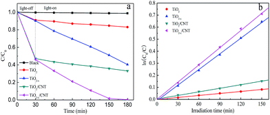 | ||
| Fig. 9 Photocatalytic activity with the different samples under visible-light irradiation (a), and variations of ln(C0/C) versus visible-light irradiation time with the different samples (b). | ||
To further demonstrate the excellent photocatalytic performance of TiO2−x/CNT, the photocatalytic hydrogen evolution rate under simulated solar light (AM 1.5) irradiation was also tested through the photocatalytic hydrogen production process.52,53 In Fig. 10a, the pure TiO2 and CNT show poor photocatalytic hydrogen evolution activity. However, TiO2−x, TiO2/CNT, and TiO2−x/CNT can be excited under visible-light to give hydrogen evolution rates of 125.13, 101.54 and 242.91 μmol h−1 g−1, respectively. These results reveal that the introduction of Ti3+ and the effect of the 3D urchin-like heterojunction structure play significant roles in the process of hydrogen generation. Fig. 10b shows the recycling hydrogen evolution reaction used to examine the photocatalytic stability of TiO2−x/CNT. The H2 evolution rates remain almost constant after five cycles lasting 25 h, which indicates the high stability of the TiO2−x/CNT composite.
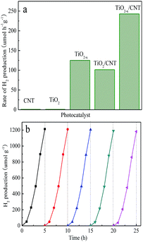 | ||
| Fig. 10 Photocatalytic hydrogen evolution for the different samples under AM 1.5 irradiation (a), and recyclability of TiO2−x/CNT for H2 evolution under AM 1.5 irradiation (b). | ||
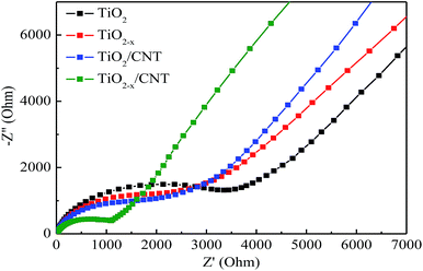
Electrochemical impedance spectroscopy (EIS) was conducted to investigate the interfacial electrical properties between electrodes and solutions. The diameters of the semicircles are equal to the charge-transfer resistance of a sample, and the tail in the low frequency region represents the diffusion process of ions in the electrode materials. Based on previous studies, a smaller semicircle diameter implies more effective separation of the photogenerated e–h pairs and/or a faster interfacial charge transfer to the electron donor–acceptor.48,54 Fig. 11 shows the Nyquist curves of pure TiO2, TiO2−x, TiO2/CNT, and TiO2−x/CNT photocatalysts. It can clearly be seen that the semicircle for TiO2−x/CNT is much smaller than that of the others. Similarly, the photocatalytic activity of TiO2−x is stronger than that of pristine TiO2. This implies that CNT and Ti3+ play an important role in improving the conductivity of the composite, which improves the rate capability of the electrode. In addition, the 3D urchin-like heterojunction structures also contribute to a decrease in the charge transfer resistance and charge recombination, and thus result in improved electrochemical properties.55–57
The electron charge transfer mechanism during the photoexcitation of the composites was investigated and is proposed in Fig. 12. Ti3+ and oxygen vacancy are introduced in the conduction band (CB) of TiO2, which narrow the band gap and enhance the visible-light absorption. Therefore, the electrons in the valence band (VB) can easily transfer to the CB of TiO2 under visible-light irradiation. Furthermore, CNT with their unique properties play an important role in improving the electron charge transfer efficiency during visible-light irradiation. The strong interaction between CNT and TiO2 allows the migration of electrons from TiO2 to CNT, which consequently reduces the chance of electron–hole recombination and accelerates the formation of superoxide anion radicals (˙O2−). These processes can lead indirectly to the generation of ˙OH radicals. ˙OH and ˙O2− with strong oxidation ability can cause the degradation of organic pollutants. In addition, the excited electrons in the CB on the surface can reduce H+ ions for the evolution of H2. Therefore, the photocatalytic hydrogen production capacity of the photocatalyst is also improved.
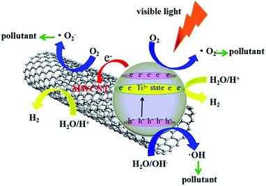 | ||
| Fig. 12 Schematic of the visible-light-driven photocatalytic mechanism for the TiO2−x/CNT composite. | ||
Conclusions
In conclusion, a 3D urchin-like black TiO2−x/CNT structured photocatalyst was successfully developed via a facile one-pot solvothermal method. Under visible-light irradiation, the results show that the prominently improved photocatalytic activity and electrochemical properties were direct consequences of the urchin-like heterojunction structure and Ti3+ species in the frameworks. The 3D urchin-like black TiO2−x/CNT has the highest MO degradation ratio, H2 evolution, and conductivity compared with pristine TiO2, TiO2−x, TiO2/CNT, and TiO2−x/CNT. In particular, MO could be photocatalytically degraded completely by TiO2−x/CNT heterojunctions in 150 min under visible-light irradiation, and a hydrogen evolution rate of 242.91 μmol h−1 g−1 could be achieved. The excellent photocatalytic activity and electrochemical property of TiO2−x/CNT is ascribed to the synergistic effect of CNT composited TiO2, Ti3+ self-doping, and the 3D urchin-like heterojunction structure. The prepared novel 3D urchin-like heterojunction photocatalyst will provide a new insight for the rational design of other functional materials and contribute to solve the increasing environmental pollution puzzles.Acknowledgements
We gratefully acknowledge the support to this research by the National Natural Science Foundation of China (21376065, 81302511, 81573134, 21106035 and 51672073), the Natural Science Foundation of Heilongjiang Province (QC2012C001, QC2013C079 and E201456), the Heilongjiang Postdoctoral Startup Fund (LBH-Q14135), the Program for New Century Excellent Talents in University of Heilongjiang Province (1253-NCET-020), the University Nursing Program for Young Scholars with Creative Talents in Heilongjiang Province (UNPYSCT-2015014) and the Youth Science and Technology Innovation Talent Program in Education Department of Heilongjiang Province (UNPYSCT-2016018).Notes and references
- J. Ran, J. Zhang, J. Yu, M. Jaroniec and S. Z. Qiao, Chem. Soc. Rev., 2014, 43, 7787 RSC.
- Z. Xing, W. Zhou, F. Du, Y. Qu, G. Tian, K. Pan, C. Tian and H. Fu, Dalton Trans., 2014, 43, 790 RSC.
- L. Zhang, Z. Xing, H. Zhang, Z. Li, X. Wu, X. Zhang, Y. Zhang and W. Zhou, Appl. Catal., B, 2016, 180, 521 CrossRef CAS.
- I. Y. Jeon, M. J. Ju, J. Xu, H. J. Choi, J. M. Seo, M. J. Kim, I. T. Choi, H. M. Kim, J. C. Kim, J. J. Lee, H. K. Liu, H. K. Kim, S. Dou, L. Dai and J. B. Baek, Adv. Funct. Mater., 2015, 25, 1170 CrossRef CAS.
- S. Li, Y. Luo, W. Lv, W. Yu, S. Wu, P. Hou, Q. Yang, Q. Meng, C. Liu and H. M. Cheng, Adv. Energy Mater., 2011, 1, 486 CrossRef CAS.
- C. Dinh, H. Yen, F. Kleitz and T. Do, Angew. Chem., Int. Ed., 2014, 53, 6618 CrossRef CAS PubMed.
- S. Ullah, E. P. Ferreira-Neto, A. A. Pasa, C. C. J. Alcântara, J. J. S. Acuna, S. A. Bilmes, M. L. M. Ricci, R. Landers, T. Z. Fermino and U. P. Rodrigues-Filho, Appl. Catal., B, 2015, 179, 333 CrossRef CAS.
- X. Liu, G. Dong, S. Li, G. Lu and Y. Bi, J. Am. Chem. Soc., 2016, 138, 2917 CrossRef CAS PubMed.
- Z. Xing, J. Li, Q. Wang, W. Zhou, G. Tian, K. Pan, C. Tian, J. Zou and H. Fu, Eur. J. Inorg. Chem., 2013, 2013, 2411 CrossRef CAS.
- G. Y. Yu, W. Zhang, Y. Sun, T. Xie, A. Ren, X. Zhou and G. Liu, J. Mater. Chem. A, 2013, 1 Search PubMed.
- N. Liu, V. Haublein, X. Zhou, U. Venkatesan, M. Hartmann, M. Mackovic, T. Nakajima, E. Spiecker, A. Osvet, L. Frey and P. Schmuki, Nano Lett., 2015, 15, 6815 CrossRef CAS PubMed.
- Z. Xing, W. Zhou, F. Du, L. Zhang, Z. Li, H. Zhang and W. Li, ACS Appl. Mater. Interfaces, 2014, 6, 16653 CAS.
- J. Dong, J. Han, Y. Liu, A. Nakajima, S. Matsushita, S. Wei and W. Gao, ACS Appl. Mater. Interfaces, 2014, 6, 1385 CAS.
- K. Hemalatha, A. S. Prakash, K. Guruprakash and M. Jayakumar, J. Mater. Chem. A, 2014, 2, 1757 CAS.
- M. Ge, C. Cao, J. Huang, S. Li, Z. Chen, K. Zhang, S. S. Al-Deyab and Y. Lai, J. Mater. Chem. A, 2016, 4, 6772 CAS.
- W. Zhou, F. Sun, K. Pan, G. Tian, B. Jiang, Z. Ren, C. Tian and H. Fu, Adv. Funct. Mater., 2011, 21, 1922 CrossRef CAS.
- V. Etacheri, M. K. Seery, S. J. Hinder and S. C. Pillai, Adv. Funct. Mater., 2011, 21, 3744 CrossRef CAS.
- J. Eom, S. Lim, S. Lee, W. Ryu and H. Kwon, J. Mater. Chem. A, 2015, 3, 11183 CAS.
- K. K. Adepalli, M. Kelsch, R. Merkle and J. Maier, Adv. Funct. Mater., 2013, 23, 1798 CrossRef CAS.
- X. Y. Pan, M. Q. Yang, X. Z. Fu, N. Zhang and Y. J. Xu, Nanoscale, 2013, 5, 3601 RSC.
- S. M. Prokes, J. L. Gole, X. B. Chen, C. Burda and W. E. Carlos, Adv. Funct. Mater., 2005, 15, 161 CrossRef CAS.
- X. Chen, L. Liu, P. Y. Yu and S. S. Mao, Science, 2011, 331, 746 CrossRef CAS PubMed.
- J. Y. Shin, J. H. Joo, D. Samuelis and J. Maier, Chem. Mater., 2012, 24, 543 CrossRef CAS.
- A. Naldoni, M. Allieta, S. Santangelo, M. Marelli, F. Fabbri, S. Cappelli, C. L. Bianc-hi, R. Psaro and V. D. Santo, J. Am. Chem. Soc., 2012, 134, 7600 CrossRef CAS PubMed.
- C. Tang, L. Liu, Y. Li and Z. Bian, Appl. Catal., B, 2016, 16, 0926 Search PubMed.
- C. Yang, Z. Wang, T. Lin, H. Yin, X. Lu, D. Wan, T. Xu, C. Zheng, J. Lin, F. Huang, X. Xie and M. Jiang, J. Am. Chem. Soc., 2013, 135, 17831 CrossRef CAS PubMed.
- T. Lin, C. Yang, Z. Wang, H. Yin, X. Lv, F. Huang, J. Lin, X. Xie and M. Jiang, Energy Environ. Sci., 2014, 7, 967 CAS.
- Y. Yan, J. Miao, Z. Yang, F. Xiao, H. Yang, B. Liu and Y. Yang, Chem. Soc. Rev., 2015, 44, 3295 RSC.
- Z. Wang, C. Yang, T. Lin, H. Yin, P. Chen, D. Wan, F. Xu, F. Huang, J. Lin, X. Xie and M. Jiang, Energy Environ. Sci., 2013, 6, 3007 CAS.
- Q. Zhang, J. Huang, W. Qian, Y. Zhang and F. Wei, Small, 2013, 9, 1237 CrossRef CAS PubMed.
- H. Zhou, L. Liu, X. Wang, F. Liang, S. Bao, D. Lv, Y. Tang and D. Jia, J. Mater. Chem. A, 2013, 1, 8525 CAS.
- N. G. Akalework, C. Pan, W. Su, J. Rick, M. C. Tsai, J. F. Lee, J. M. Lin, L. D. Tsai and B. J. Hwang, J. Mater. Chem., 2012, 22, 20977 RSC.
- K. Hemalatha, P. M. Ette, G. Madras and K. Ramesha, J. Sol-Gel Sci. Technol., 2015, 73, 72 CrossRef CAS.
- M. Gui, S. Chai, B. Xu and A. R. Mohamed, Sol. Energy Mater. Sol. Cells, 2014, 122, 183 CrossRef CAS.
- K. Fan, T. Peng, J. Chen, X. Xiao and R. Li, J. Power Sources, 2013, 222, 38 CrossRef CAS.
- Z. He, J. Liu, J. Miao, B. Liu and T. Tan, J. Mater. Chem. C, 2014, 2, 1381 RSC.
- J. Huo, Y. Hu, H. Jiang and C. Li, Nanoscale, 2014, 6, 9078 RSC.
- Z. Chena, Z. Mab, J. Songb and L. Wang, J. Power Sources, 2016, 324, 86 CrossRef.
- W. Zhou, W. Li, J. Wang, Y. Qu, Y. Yang, Y. Xie, K. Zhang, L. Wang, H. Fu and D. Zhao, J. Am. Chem. Soc., 2014, 136, 9280 CrossRef CAS PubMed.
- N. Li, G. Liu, C. Zhen, F. Li, L. Zhang and H. Cheng, Adv. Funct. Mater., 2011, 21, 1717 CrossRef CAS.
- X. Liao, R. Gerdts, S. F. Parker, L. Chi, Y. Zhao, M. Hill, J. Guo, M. O. Jones and Z. Jiang, Phys. Chem. Chem. Phys., 2016, 18, 17311 RSC.
- W. Hu, W. Zhou, K. Zhang, X. Zhang, L. Wang, B. Jiang, G. Tian, D. Zhao and H. Fu, J. Mater. Chem. A, 2016, 4, 7495 CAS.
- B. Xia, S. Ding, H. Wu, X. Wang and X. Lou, RSC Adv., 2012, 2, 792 RSC.
- R. R. N. Marques, B. F. Machado, J. L. Faria and A. M. T. Silva, Carbon, 2010, 48, 1515 CrossRef CAS.
- J. Di, Z. Yong, Z. Yao, X. Liu, X. Shen, B. Sun, Z. Zhao and H. He, Small, 2013, 9, 148 CrossRef CAS PubMed.
- J. Wang, R. Ran, M. O. Tade and Z. P. Shao, J. Power Sources, 2014, 254, 18 CrossRef CAS.
- H. Ming, H. Huang, K. Pan, H. Li, Y. Liu and Z. Kang, J. Solid State Chem., 2012, 192, 305 CrossRef CAS.
- J. Yu, T. Ma and S. Liu, Phys. Chem. Chem. Phys., 2011, 13, 3491 RSC.
- W. Hou and S. B. Cronin, Adv. Funct. Mater., 2013, 23, 1612 CrossRef CAS.
- B. Czech, W. Buda, S. P. Patkowska and P. Oleszczuk, Appl. Catal., B, 2015, 162, 564 CrossRef CAS.
- C. Hung, C. Yuan and H. Li, J. Hazard. Mater., 2017, 322, 243 CrossRef CAS PubMed.
- L. Wang, X. Duan, G. Wang, C. Liu, S. Luo, S. Zhang, Y. Zeng, Y. Xu, Y. Liu and X. Duan, Appl. Catal., B, 2016, 186, 88 CrossRef CAS.
- C. Liu, L. Wang, Y. Tang, S. Luo, Y. Liu, S. Zhang, Y. Zeng and Y. Xu, Appl. Catal., B, 2015, 164, 1 CrossRef CAS.
- L. Huang, Q. Chan, X. Wu, H. Wang and Y. Liu, J. Ind. Eng. Chem., 2012, 18, 574 CrossRef CAS.
- G. Xi, J. Ye, Q. Ma, N. Su, H. Bai and C. Wang, J. Am. Chem. Soc., 2012, 134, 6508 CrossRef CAS PubMed.
- Z. Liu, J. Liu, J. Liu, L. Wang, G. Zhang and X. Sun, Phys. Chem. Chem. Phys., 2014, 16, 8808 RSC.
- W. Ren, H. Zhang, D. Kong, B. Liu, Y. Yang and C. Cheng, Phys. Chem. Chem. Phys., 2014, 16, 22953 RSC.
| This journal is © The Royal Society of Chemistry 2017 |

