 Open Access Article
Creative Commons Attribution 3.0 Unported Licence
Magnetic and magneto-optical properties of nickel hexacyanoferrate/chromate thin films†
Magdalena Fitta *a,
Helena Prima-Garciab,
Paweł Czajac,
Tomasz Korzeniakd,
Michał Krupińskia,
Marcin Wojtyniakef and
Maria Bałandaa
aInstitute of Nuclear Physics Polish Academy of Sciences, PL-31342 Krakow, Poland
bInstituto de Ciencia Molecular (ICMol), Universitat de València, C/Catedrático José Beltrán, 2, 46980-Paterna, Spain. E-mail: Magdalena.Fitta@ifj.edu.pl
cInstitute of Metallurgy and Materials Science Polish Academy of Sciences, Reymonta 25, 30-059, Kraków, Poland
dFaculty of Chemistry, Jagiellonian University, Ingardena 3, 30-060, Kraków, Poland
eInstitute of Physics, University of Silesia, Uniwersytecka 4, Katowice, Poland
fSilesian Center for Education and Interdisciplinary Research, 75 Pułku Piechoty 1A, Chorzów, Poland
First published on 5th January 2017
Abstract
One of the most important challenges of modern science and technology is the quest for novel and tuneable materials, the properties of which can be widely controlled by chemical modifications or external stimuli. Simultaneously, an interest in the development of magnetic thin films also gains significant attention. In the current paper we bring together both these challenges and present a study of a new type of low-dimensional nickel hexacyanoferrate/chromate system. Thin films were obtained by the “layer by layer” deposition technique, where the ratio of Fe/Cr was controlled by the dipping sequence. The scope of this work is a comprehensive analysis of structural, spectroscopic and magnetic properties of the compound and the investigation of the evolution of material properties induced by the change of the chemical composition.
Introduction
Over the past few years, a significant interest in the study of molecular magnets in the form of thin films emerged. Low-dimensional assemblies have assumed remarkable importance due to their unique properties, which make them attractive for future application e.g. in spintronic devices. Among the group of cyanido-bridged coordination networks, the most studied compounds are thin films of hexacyanidometallates, Prussian blue analogues (PBA). These compounds are cyano-bridged coordination networks with face-centered crystal structure containing hexacyanometalates [M(CN)6]n− and transition metals ions Mn+. PBAs gain considerable attention mostly because of their unique properties such as room temperature ferromagnetism, photomagnetism and compensation point.1–3 In recent years the importance of these materials has grown in relation to the possibility of their synthesis in the form of thin films by chemical methods. The most important advantages of thin films of PBAs are: transparency in the visible region and charge-transfer properties, which makes these materials good candidates for the applications in optoelectronic devices. Thin films of PBAs can also be interesting materials for the fabrication of future molecule-based spintronic devices combining magnetooptical properties and spin transport.4Few methods for preparation of PBA thin films were reported including electrodeposition,5–7 Langmuir–Blodgett technique,8,9 and multi-sequential “layer by layer” deposition method.10,11 The latter technique offers the possibility of the precise control over the deposition process encompassing the careful control of the growth kinetics, thickness and roughness as well as chemical composition of the resultant films. This can be easily achieved by the appropriate use of multi-sequential adsorption. In this paper we report the successful fabrication of a new nickel hexacyanoferrate/chromate thin film, whose chemical composition was devised by the sequence of dipping cycles. Due to the highly symmetrical structure of the PBA its properties can be tuned by changing the metal centres involved in the cyano-bridging.
Here we present the new nickel hexacyanoferrate/chromate compound obtained by layer by layer deposition, where [Cr(CN)6]3−![[thin space (1/6-em)]](https://www.rsc.org/images/entities/char_2009.gif) :
:![[thin space (1/6-em)]](https://www.rsc.org/images/entities/char_2009.gif) [Fe(CN)6]3− ratio is 0.81
[Fe(CN)6]3− ratio is 0.81![[thin space (1/6-em)]](https://www.rsc.org/images/entities/char_2009.gif) :
:![[thin space (1/6-em)]](https://www.rsc.org/images/entities/char_2009.gif) 1.19. The properties of this material fall exactly between the properties of pure nickel hexacyanoferrate and nickel hexacyanochromate samples.
1.19. The properties of this material fall exactly between the properties of pure nickel hexacyanoferrate and nickel hexacyanochromate samples.
Experimental
The films preparation
All reagents were purchased from Sigma-Aldrich and used without further purification. Samples reported herein were obtained by sequential adsorption of Ni2+ and M(CN)63− (M = Fe, Cr) from aqueous solution onto solid support.Mica and silicon were selected as substrates for films growth. Silicon (100) (from CrysTec) was cleaned upon alternating ultrasonification in acetone, isopropanol and DI water for 3 min. Afterwards Si surface was cleaned using plasma cleaner, with 10 minutes of plasma treatment. Subsequently, the substrates were immersed in a 1 wt% aqueous solution of poly(diallyldimethylammonium chloride) (PDADMA, molecular weight 250![[thin space (1/6-em)]](https://www.rsc.org/images/entities/char_2009.gif) 000 (g mol−1)). Mica was rinsed with ethanol and deionized (DI) water and then used as a solid support for films manufacture.
000 (g mol−1)). Mica was rinsed with ethanol and deionized (DI) water and then used as a solid support for films manufacture.
Films were prepared with the aid of KSV Nima dip-coater at a the room temperature. The general formula of the films can be written as Ni1.5[Fe(CN)6]x[Cr(CN)6]1−x·nH2O (x = 0, 0.55 and 1) were x = nFe/(nFe + nCr). The details of the synthesis depend on x value and are given as follows:
x = 0 (sample 3, Ni1.55[Cr(CN)6]·nH2O, NiCr) and x = 1 (sample 1, Ni1.69[Fe(CN)6]·nH2O, NiFe): mica/silicon was immersed in a 20 mM aqueous solution of NiCl2 for 120 s, then rinsed with DI. In the next step substrate was placed in a 20 mM solution of potassium ferricyanide (for x = 0) or solution of K3[Cr(CN)6] (for x = 1) and again rinsed with DI. The process was repeated 200 times.
x = 0.55 (sample 2, Ni1.41[Fe(CN)6]0.55[Cr(CN)6]0.45·nH2O, Ni(Fe/Cr)): solid support was immersed in a 20 mM aqueous solution of NiCl2 for 120 s, then rinsed with DI. Then substrate was placed in a 20 mM solution of potassium ferricyanide and again rinsed with DI. In the following step solid support was immersed in a 20 mM aqueous solution of NiCl2 for 120 s, rinsed with DI and finally placed in a 20 mM solution of K3[Cr(CN)6] for 120 s. This double-step sequence was repeated 100 times.
Methods
Microstructure and composition analysis of films was performed using a FEI ESEM XL30 scanning electron microscope equipped with an X-ray energy dispersive spectrometer EDAX GEMINI 4000.The characterization of the films surface was done by the NanoWizard® 3 Atomic Force Microscope (AFM) from JPK. The AFM analysis was performed on the films deposited on silicon substrate. The measurements were performed at room temperature under ambient condition in tapping mode. The analysis was performed with the use of Gwyddion software.12 The thickness of the films was determined using AFM based on the Z-high scan of the film's scratch.
The IR spectra were recorded by means of a Nicolet iN10 FT-IR Microscope by Thermo Fisher Scientific.
Magnetic properties were measured by Quantum Design MPMS-XL magnetometer. For magnetic measurements samples deposited on mica were cut into 4 × 4 mm pieces and then introduced into the sample holder. Measurements were carried out with the applied magnetic field parallel and perpendicular to the surface of the films. Magnetic properties of the mica substrate were measured independently under the same conditions and subtracted from the raw data.
The magneto-optical characterization was performed using a self-made Kerr magnetometer. A He–Ne laser with a wavelength of 633 nm and an output power of 10 mW was used as the light source producing a nearly linearly polarized light beam. This beam was passed through a Glan-Laser Calcite polarizer with an extinction coefficient of 10−5, which allows for working with both s-polarized (electric field perpendicular to the plane of incidence) and p-polarized (electric field parallel to the plane of incidence) configurations. Temperature was measured by a Cernox CX-SD low-temperature sensor placed on top of the sample. Temperature control was performed with an accuracy of ±1 K using an ITC 503 device from Oxford Instruments. The design of the electromagnets and the cryostat allows for using of longitudinal, polar and transverse geometries. In the present case, MOKE measurements were acquired in longitudinal configuration, applying a magnetic field parallel to the surface of the film. The external magnetic field range in this configuration was ±300 mT.
Results and discussion
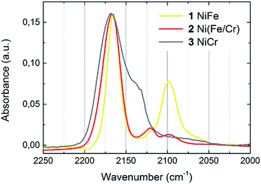
The chemical composition of thin films was determined by means of SEM EDS. The results allowed for determining of the transition metals ratios, which are given in Table 1. The formation of cyanometallate network can be confirmed by the presence of cyanide stretching modes in IR spectrum (Fig. 1). One dominant peak located at 2168 cm−1 is observed for NiCr (3) sample. This band corresponds to the Ni2+–N![[triple bond, length as m-dash]](https://www.rsc.org/images/entities/char_e002.gif) C–Cr3+ stretching. Two bands are observed for samples containing Fe. In this case the dominant peak located at 2167 cm−1 is connected with stretching of Ni2+–N
C–Cr3+ stretching. Two bands are observed for samples containing Fe. In this case the dominant peak located at 2167 cm−1 is connected with stretching of Ni2+–N![[triple bond, length as m-dash]](https://www.rsc.org/images/entities/char_e002.gif) C–Fe3+. Presence of the weaker bands (2098 cm−1) reveals partial reduction of Fe and indicates the appearance of Fe2+ in the samples. It means, that there is a mixture of Fe2+ and Fe3+ in compounds 1 and 2.
C–Fe3+. Presence of the weaker bands (2098 cm−1) reveals partial reduction of Fe and indicates the appearance of Fe2+ in the samples. It means, that there is a mixture of Fe2+ and Fe3+ in compounds 1 and 2.
| Sample | xtheor | xexp | Number of dipping cycles | Thickness | RMS roughness |
|---|---|---|---|---|---|
| 1 NiFe | 0 | 0 | 200 | 327 nm | 56 nm |
| 2 Ni(Fe/Cr) | 0.5 | 0.55 | 2 × 100 | 228 nm | 31 nm |
| 3 NiCr | 1 | 1 | 200 | 234 nm | 32 nm |
The morphology of the films was characterized by SEM Secondary Electron (SE) mode and AFM. The AFM images were acquired in tapping mode with a 5 × 5 μm scan sizes for films with various number of deposition cycles (ESI, Fig. 1†). For all samples, the complete surface coating is observed after 10 deposition cycles. Fig. 2 shows that the surface pattern of all films is composed of a collection of small grains within the range of 3 to 5 μm. The average particle size as well as the root mean square (RMS) roughness of the films surface increases with the number of deposition cycles. RMS roughness is equal to 56 nm for sample 1 (200 dipping cycles, thickness: 327 nm), 31 nm for sample 2 (2 × 100 dipping cycles, thickness 228 nm) and 32 nm for sample 3 (200 dipping cycles, thickness 234 nm). Table 1 presents the results of EDS as well as films' thickness and roughness.
 | ||
| Fig. 2 SEM SE images of the sample 1 (a), 2 (b) and 3 (c). Images present the surface of the samples obtained after 200 deposition cycles (1 and 3) and after 2 × 100 deposition cycles (sample 2). | ||
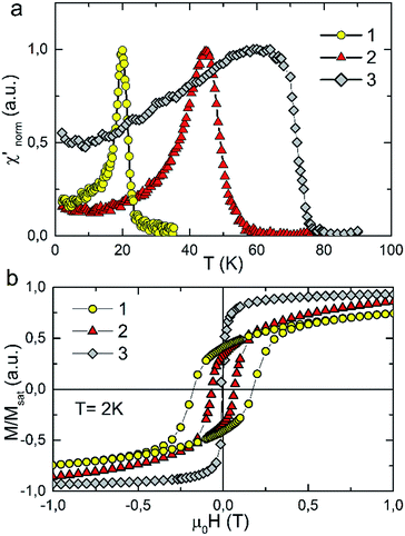
The temperature dependence of real component of AC susceptibility χac(T) of 1, 2 and 3 was measured with the films oriented parallel to the direction of the external magnetic field. AC susceptibility was measured with the frequency of 125 Hz and the amplitude of the oscillating field was equal to 3 Oe. For all samples χac(T) shows sharp peaks upon cooling which indicates the transition to the long range ordered state. The presence of one sharp peak in χac(T) recorded for Ni(Fe/Cr) sample is an evidence for the fact that the final product of the synthesis is a single phase compound. The critical temperatures determined from the minimum of dχac/dT are: 21 K, 48 K and 68 K for 1, 2 and 3 respectively. The Tc values are similar to that observed for pure 3D bulk samples of the same material.2
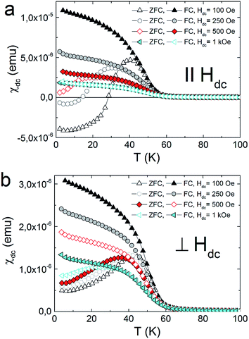
The strong dependence of magnetic properties on the Fe/Cr ratio in examined compounds is further revealed with the measurements of magnetic hysteresis. For pure NiCr sample 3 the value of coercive field is the smallest and is equal to Hc = 50 Oe. Higher value of coercive field Hc was observed for sample 2 which reaches the value of 0.67 kOe. The highest Hc = 1.77 kOe was obtained for pure NiFe sample 1. The temperature dependences of magnetization measured in zero field cooled (ZFC) and field cooled (FC) regimes for the studied samples are presented in Fig. 3. These measurements were performed for the surfaces of the films oriented either parallel or perpendicular to the external magnetic field of 100 Oe. All examined compounds show magnetic anisotropy as a much stronger magnetic response is observed for the films oriented along the direction of the magnetic field. This result is consistent with previous reports on PBAs thin films and can be explained by the modification of the internal magnetic field due to a demagnetizing effect.13
All the herein investigated compounds show large hysteretic behaviour between ZFC and FC curves. This is especially evident in the case of the samples orientated parallel with respect to the magnetic field. It is worthy to notice that in the ZFC curve, measured at Hdc = 100 Oe, negative magnetisation appears below 14 K for 1 (Fig. 4a) and below 28 K for 2 (Fig. 5a). Usually the presence of negative magnetization value in the M(T) curves is related to the compensation point, where algebraic sum of magnetization of sublattices is equal to zero and compensation temperature should not depend on the value of the external field. The presence of compensation temperature manifested itself in many examples of PBA samples in both the bulks and thin films.14–16 Nevertheless, the justification for the negative magnetization in relation to the compensation point for our samples is excluded by further ZFC–FC magnetic susceptibility measurements in the presence of Hdc = 250 Oe, 500 Oe and 1 kOe (Fig. 5). The ZFC susceptibility recorded for sample oriented parallel to magnetic field increases with an increase in the magnetic field. For Hdc equal to 500 Oe it reaches the positive value within the whole temperature range. Similar effect was observed for the bulk PBA sample based on Cu, Mn and Fe, however it was later explained as a field induced reversal of the Mn spins in the direction of Cu and Fe spins.17–19 In our case all examined compounds are expected to be ferromagnets, hence the existence of negative magnetization is not yet fully understood. Possibly it may be related to large shape anisotropy of our thin film samples and the presence of some negative remanent field of the superconducting magnet.20
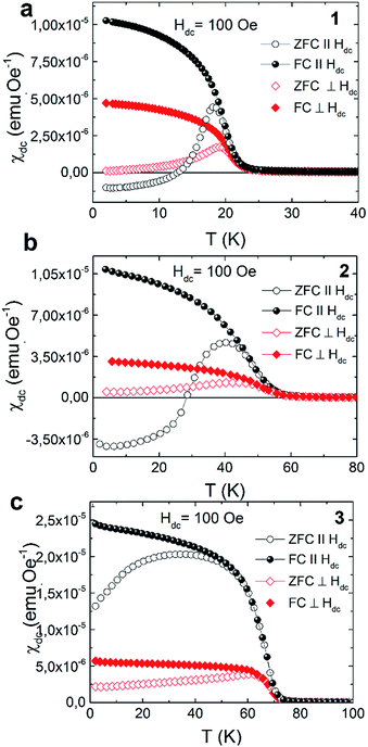 | ||
| Fig. 4 Thermal variation of the DC susceptibility measured under ZFC and FC conditions in applied field of 100 Oe for 1 (a), 2 (b) and 3 (c). | ||
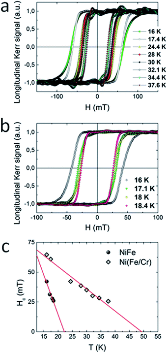
The magnetic properties of 1 (100 dipping cycles) and 2 (2 × 50 dipping cycles) thin films were in addition more directly examined by the use of magneto-optical Kerr effect (MOKE) measurements. In this technique, the Kerr rotation (θK) of the films is proportional to the magnetization of the sample and is recorded as a function of the applied magnetic field. For both compounds measured in longitudinal configuration (magnetic field parallel to the sample surface) large hysteresis loops appeared at 16 K (Fig. 6a and b), while in polar configuration the MOKE signal was not observed. This result is consistent with the results obtained by SQUID magnetometer, where the signal of magnetization was much higher for films oriented parallel to the external magnetic field, what confirms the anisotropic nature of the samples. Moreover, upon heating of the system, the evolution of the coercive field was monitored. For both compounds the increase of temperature brings about the decrease of coercive field. From the linear extrapolation of Hc(T) dependence, Tc = 22 K for 1 and Tc = 48 K for 2 was determined (Fig. 6c). These values are consistent with these obtained from dχac/dT plot. Very good agreement of critical temperatures obtained by SQUID and MOKE measurements indicates that our films are not contaminated by any magnetic species including oxides.
Conclusions
In summary it has been demonstrated that well-defined films of Prussian blue analogues of general formula NiII1.5[FeIII(CN)6]x[CrIII(CN)6]1−x·nH2O (x = 0, 0.55 and 1) can be successfully produced using multisequential adsorption technique. This method enables precise control of film's thickness as well as its chemical composition. All presented samples show magnetic anisotropy, which can be explained by demagnetizing effect. Moreover it is shown, that control of the Fe/Cr ratio allows for tuning of the desired magnetic properties of the obtained compounds. An increase in the Fe content leads to the decrease of the critical temperature whereas the coercive field increases. Likewise, these materials further offer outstanding magneto-optical response, due to high intensity of the reflected light from the homogeneous films surface. MOKE magnetometry was also used for the proper determination of critical temperatures and the obtained results are in agreement with these obtained with SQUID magnetometry.Acknowledgements
This work was supported by the Polish National Science Centre within the frame of Project No. UMO-2011/03/D/ST5/05400.References
- K. Hashimoto and S. Ohkoshi, Philos. Trans. R. Soc., A, 1999, 357, 2977 CrossRef CAS.
- M. Verdaguer and G. Girolami, Magnetic Prussian blue analogs, in Magnetoscience: molecules to materials, Wiley, Weinheim, Germany, 2005, vol. 5 Search PubMed.
- O. Sato, T. Iyoda, A. Fujishima and K. Hashimoto, Science, 1996, 271, 49 CAS.
- E. Coronado, J. P. Prieto-Ruiz and H. Prima-Garcia, Chem. Commun., 2013, 49, 10145 RSC.
- S. Ohkoshi, A. Fujishima and K. Hashimoto, J. Am. Chem. Soc., 1998, 120, 5349 CrossRef CAS.
- E. Coronado, M. Fitta, J. P. Prieto-Ruiz, H. Prima-Garcia, F. M. Romero and A. Cros, J. Mater. Chem. C, 2013, 1, 6981 RSC.
- E. Coronado, M. Makarewicz, J. P. Prieto-Ruiz, H. Prima-Garcia and F. M. Romero, Adv. Mater., 2011, 23, 4323 CrossRef CAS PubMed.
- M. Clemente-Leon, E. Coronado, A. Lopez-Munoz, D. Repetto, C. Mingotaud, D. Brinzei, L. Catala and T. Mallah, Chem. Mater., 2008, 20, 4642 CrossRef CAS.
- T. Yamamotoa, Y. Umemurab, O. Satoc and Y. Einaga, Sci. Technol. Adv. Mater., 2006, 7, 134 CrossRef.
- M. Pyrasch, A. Toutianoush, W. Jin, J. Schnepf and B. Tieke, Chem. Mater., 2003, 15, 245 CrossRef CAS.
- J. T. Culp, J. Park, I. O. Benitez, Y. Huh, M. W. Meisel and D. R. Talham, Chem. Mater., 2003, 15, 3431 CrossRef CAS.
- D. Nečas and P. Klapetek, Cent. Eur. J. Phys., 2012, 10, 181 Search PubMed.
- D. Pajerowski, J. E. Gardner, D. R. Tahlam and M. W. Meisel, New J. Chem., 2011, 35, 1320 RSC.
- S. Ohkoshi, T. Iyoda, A. Fujishima and K. Hashimoto, Phys. Rev. B: Condens. Matter Mater. Phys., 1997, 56, 11642 CrossRef CAS.
- S. Ohkoshi, A. Fujishima and K. Hashimoto, J. Am. Chem. Soc., 1998, 120, 5349 CrossRef CAS.
- M. Zentková, M. Mihalik, Z. Arnold and J. Kamarád, J. Phys.: Conf. Ser., 2010, 200, 022074 CrossRef.
- D. Lahiri, Y. Choi, S. M. Yusuf, A. Kumar, N. Ramanan, S. Chattopadhyay, D. Haskel and S. M. Sharma, Mater. Res. Express, 2016, 3, 036101 CrossRef.
- A. Kumar, S. M. Yusuf, L. Keller and J. V. Yakhmi, Phys. Rev. Lett., 2008, 101, 207206 CrossRef PubMed.
- S. M. Yusuf, A. Kumar and J. V. Yakhmi, Appl. Phys. Lett., 2009, 95, 182506 CrossRef.
- A. Kumar and S. M. Yusuf, Phys. Rep., 2015, 556, 1 CrossRef CAS.
Footnote |
| † Electronic supplementary information (ESI) available. See DOI: 10.1039/c6ra25775e |
| This journal is © The Royal Society of Chemistry 2017 |

